
User Guide
Page 15
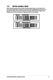
With the correct serial number of the product's serial number containing 14 characters such as xxS0xxxxxxxxxx shown as the figure below. 1.2 Serial number label Before requesting support from the ASUS Technical Support team, you must take note of the product, ASUS Technical Support team members can then offer a quicker and satisfying solution to your problems. RS520-E8-RS8 xxS0xxxxxxxxxx RS520-E8-RS12-E xxS0xxxxxxxxxx ASUS RS520-E8-RS8, RS520-E8-RS12-E 1-3
With the correct serial number of the product's serial number containing 14 characters such as xxS0xxxxxxxxxx shown as the figure below. 1.2 Serial number label Before requesting support from the ASUS Technical Support team, you must take note of the product, ASUS Technical Support team members can then offer a quicker and satisfying solution to your problems. RS520-E8-RS8 xxS0xxxxxxxxxx RS520-E8-RS12-E xxS0xxxxxxxxxx ASUS RS520-E8-RS8, RS520-E8-RS12-E 1-3
User Guide
Page 16
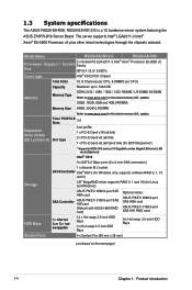
supports software RAID 0, 1, 10 and 5) LSI® MegaRAID driver supports RAID 0, 1 and 10) (for the latest memory AVL update. Model Name RS520-E8-RS12-E RS520-E8-RS8 Processor Support / System 2 x Socket R3 LGA 2011-3 Intel® Xeon® Processor E5-2600 v3 Family Bus QPI 6.4 / 8.0 / 9.6GT/s Core Logic Intel®...) Intel® C612 9 x SATA 6 Gbps ports (8 x 2 mini-SAS connectors) Storage 1 x discrete M.2 socket SATA Controller Intel® RSTe (for Windows only; 1.3 System specifications The ASUS RS520-E8-RS8, RS520-E8-RS12-E is a 1U barebone server system featuring the...
supports software RAID 0, 1, 10 and 5) LSI® MegaRAID driver supports RAID 0, 1 and 10) (for the latest memory AVL update. Model Name RS520-E8-RS12-E RS520-E8-RS8 Processor Support / System 2 x Socket R3 LGA 2011-3 Intel® Xeon® Processor E5-2600 v3 Family Bus QPI 6.4 / 8.0 / 9.6GT/s Core Logic Intel®...) Intel® C612 9 x SATA 6 Gbps ports (8 x 2 mini-SAS connectors) Storage 1 x discrete M.2 socket SATA Controller Intel® RSTe (for Windows only; 1.3 System specifications The ASUS RS520-E8-RS8, RS520-E8-RS12-E is a 1U barebone server system featuring the...
User Guide
Page 17
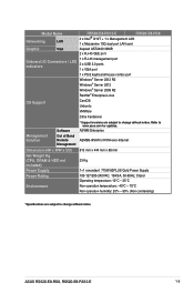
ASWM Enterprise ASMB8-iKVM for updates. Model Name Networking LAN RS520-E8-RS12-E RS520-E8-RS8 2 x Intel® I210T + 1 x Management LAN 1 x Mezzanine 10G dual port LAN card Graphic VGA Aspeed AST2400 32MB 2 x RJ-45 GbE port 1 x ... operation temperature: -40°C - 70°C Non operation humidity: 20% - 90% (Non condensing) *Specifications are subject to change without notice. ASUS RS520-E8-RS8, RS520-E8-RS12-E 1-5 Refer to www.asus.com for KVM-over-Internet Dimension (HH x WW x DD) Net Weight Kg (CPU, DRAM & HDD not included) Power Supply Power Rating Environment...
ASWM Enterprise ASMB8-iKVM for updates. Model Name Networking LAN RS520-E8-RS12-E RS520-E8-RS8 2 x Intel® I210T + 1 x Management LAN 1 x Mezzanine 10G dual port LAN card Graphic VGA Aspeed AST2400 32MB 2 x RJ-45 GbE port 1 x ... operation temperature: -40°C - 70°C Non operation humidity: 20% - 90% (Non condensing) *Specifications are subject to change without notice. ASUS RS520-E8-RS8, RS520-E8-RS12-E 1-5 Refer to www.asus.com for KVM-over-Internet Dimension (HH x WW x DD) Net Weight Kg (CPU, DRAM & HDD not included) Power Supply Power Rating Environment...

User Guide
Page 19
The I/O shields with openings for techincians only. 1.5 Rear panel features 4 3 2 1 The rear panel includes the expansion slots, system power sockets, and rear fans. ASUS RS520-E8-RS8, RS520-E8-RS12-E 1-7 RS520-E8-RS8 PS/2 keyboard/mouse cpmbo port LAN port 2 VGA port Serial port (optional) Redundant power supply Mezzanine 10G dual-port LAN card (optional) Power connector DM ...
The I/O shields with openings for techincians only. 1.5 Rear panel features 4 3 2 1 The rear panel includes the expansion slots, system power sockets, and rear fans. ASUS RS520-E8-RS8, RS520-E8-RS12-E 1-7 RS520-E8-RS8 PS/2 keyboard/mouse cpmbo port LAN port 2 VGA port Serial port (optional) Redundant power supply Mezzanine 10G dual-port LAN card (optional) Power connector DM ...
User Guide
Page 21
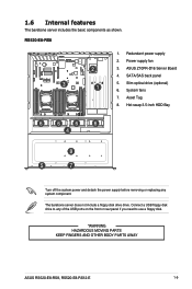
...-D16 Server Board 4. Connect a USB floppy disk drive to use a floppy disk. *WARNING HAZARDOUS MOVING PARTS KEEP FINGERS AND OTHER BODY PARTS AWAY ASUS RS520-E8-RS8, RS520-E8-RS12-E 1-9 System fans 7. Hot-swap 3.5-inch HDD Bay 6 6 6 6 4 8 5 7 Turn off the system power and detach the power supply before removing or replacing any of the ... panel if you need to any system component. The barebone server does not include a floppy disk drive drive. SATA/SAS back panel 3 5. Redundant power supply 2. RS520-E8-RS8 1.
...-D16 Server Board 4. Connect a USB floppy disk drive to use a floppy disk. *WARNING HAZARDOUS MOVING PARTS KEEP FINGERS AND OTHER BODY PARTS AWAY ASUS RS520-E8-RS8, RS520-E8-RS12-E 1-9 System fans 7. Hot-swap 3.5-inch HDD Bay 6 6 6 6 4 8 5 7 Turn off the system power and detach the power supply before removing or replacing any of the ... panel if you need to any system component. The barebone server does not include a floppy disk drive drive. SATA/SAS back panel 3 5. Redundant power supply 2. RS520-E8-RS8 1.

User Guide
Page 23
1.7 LED information 1.7.1 Front panel LEDs RS520-E8-RS8 LAN4 LED (for Mezzanine card) LAN3 LED (for Mezzanine card) LAN2 LED LAN1 LED Message LED HDD Access LED RS520-E8-RS12-E Power button with LED Message LED Location button with LED LAN1 LED LAN2 LED 4 3 2 1 Location button with LED ...No activity Blinking Read/write data into the HDD OFF System is pressed Normal status (Press the location switch again to turn off) ASUS RS520-E8-RS8, RS520-E8-RS12-E 1-11 no incoming event ON With the onboard ASMB8-iKVM: a hardware monitor event is indicated OFF No LAN connection Blinking LAN...
1.7 LED information 1.7.1 Front panel LEDs RS520-E8-RS8 LAN4 LED (for Mezzanine card) LAN3 LED (for Mezzanine card) LAN2 LED LAN1 LED Message LED HDD Access LED RS520-E8-RS12-E Power button with LED Message LED Location button with LED LAN1 LED LAN2 LED 4 3 2 1 Location button with LED ...No activity Blinking Read/write data into the HDD OFF System is pressed Normal status (Press the location switch again to turn off) ASUS RS520-E8-RS8, RS520-E8-RS12-E 1-11 no incoming event ON With the onboard ASMB8-iKVM: a hardware monitor event is indicated OFF No LAN connection Blinking LAN...

User Guide
Page 27
... of the PnP cap. 2.2.1 Installing the CPU To install a CPU: 1. Remove the screw with a Philip screw driver and then remove the air duct. ASUS RS520-E8-RS8, RS520-E8-RS12-E 2-3 2.2 Central Processing Unit (CPU) The motherboard comes with two surface mount LGA 2011-3 sockets designed for the position of the air duct). Ensure that... all power cables are for the Intel® Xeon E5-2600 v3 processor family. ASUS shoulders the repair cost only if the damage is shipment/transitrelated. • Keep the cap after installing the motherboard.
... of the PnP cap. 2.2.1 Installing the CPU To install a CPU: 1. Remove the screw with a Philip screw driver and then remove the air duct. ASUS RS520-E8-RS8, RS520-E8-RS12-E 2-3 2.2 Central Processing Unit (CPU) The motherboard comes with two surface mount LGA 2011-3 sockets designed for the position of the air duct). Ensure that... all power cables are for the Intel® Xeon E5-2600 v3 processor family. ASUS shoulders the repair cost only if the damage is shipment/transitrelated. • Keep the cap after installing the motherboard.

User Guide
Page 29
Press the left load lever (D), move it to slightly lift the load plate (G). Do not insert the load lever into the retention tab. 6. Gently push the right load lever down to the right (E) until it is released from then retention tab (F), then gently pull it until it is fully extended. 5. Hold the edge then gently lift the load plate (H). edge of the Load plate Load plate Load lever ASUS RS520-E8-RS8, RS520-E8-RS12-E 2-5 4.
Press the left load lever (D), move it to slightly lift the load plate (G). Do not insert the load lever into the retention tab. 6. Gently push the right load lever down to the right (E) until it is released from then retention tab (F), then gently pull it until it is fully extended. 5. Hold the edge then gently lift the load plate (H). edge of the Load plate Load plate Load lever ASUS RS520-E8-RS8, RS520-E8-RS12-E 2-5 4.

User Guide
Page 31
PnP cap 12. 11. edge of the load plate is fixed and tucked securely under the lever (L), then insert the right load lever under the lever (J), then the PnP cap will eject automatically. Push the reght load lever down (I) ensuring that the edge of the load plate is fixed and tucked securely under the retention tab (M). Push the left load lever down (K) ensuring that the edge of load plate Load lever Retention tab ASUS RS520-E8-RS8, RS520-E8-RS12-E 2-7
PnP cap 12. 11. edge of the load plate is fixed and tucked securely under the lever (L), then insert the right load lever under the lever (J), then the PnP cap will eject automatically. Push the reght load lever down (I) ensuring that the edge of the load plate is fixed and tucked securely under the retention tab (M). Push the left load lever down (K) ensuring that the edge of load plate Load lever Retention tab ASUS RS520-E8-RS8, RS520-E8-RS12-E 2-7
User Guide
Page 33
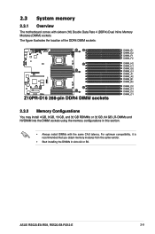
.... • Start installing the DIMMs in this section. • Always install DIMMs with sixteen (16) Double Data Rate 4 (DDR4) Dual Inline Memory Modules (DIMM) sockets. ASUS RS520-E8-RS8, RS520-E8-RS12-E 2-9 2.3 System memory 2.3.1 Overview The motherboard comes with the same CAS latency. The figure illustrates the location of the DDR4 DIMM sockets: 2.3.2 Memory Configurations You...
.... • Start installing the DIMMs in this section. • Always install DIMMs with sixteen (16) Double Data Rate 4 (DDR4) Dual Inline Memory Modules (DIMM) sockets. ASUS RS520-E8-RS8, RS520-E8-RS12-E 2-9 2.3 System memory 2.3.1 Overview The motherboard comes with the same CAS latency. The figure illustrates the location of the DDR4 DIMM sockets: 2.3.2 Memory Configurations You...
User Guide
Page 35
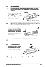
... a DIMM into the socket VERTICALLY to unplug the power supply before adding or removing DIMMs or other system components. Apply force to unlock the DIMM. 2. ASUS RS520-E8-RS8, RS520-E8-RS12-E 2-11 The DIMM might get damaged when it fits in the wrong direction to both of the DIMM simultaneously until the retaining clips snaps...
... a DIMM into the socket VERTICALLY to unplug the power supply before adding or removing DIMMs or other system components. Apply force to unlock the DIMM. 2. ASUS RS520-E8-RS8, RS520-E8-RS12-E 2-11 The DIMM might get damaged when it fits in the wrong direction to both of the DIMM simultaneously until the retaining clips snaps...

User Guide
Page 37
... interface on the drive connects to install other 3.5-inch SATA II/SAS HDDs. 2.4.2 Installing a 2.5-inch SSD (only RS520-E8-RS12-E) To install a 2.5-inch SSD: 1. B A When installed, the SATA II/SAS connector on the backplane. 6. ASUS RS520-E8-RS8, RS520-E8-RS12-E 2-13 5. The drive tray is correctly placed when its front edge aligns with the bay edge. Press...
... interface on the drive connects to install other 3.5-inch SATA II/SAS HDDs. 2.4.2 Installing a 2.5-inch SSD (only RS520-E8-RS12-E) To install a 2.5-inch SSD: 1. B A When installed, the SATA II/SAS connector on the backplane. 6. ASUS RS520-E8-RS8, RS520-E8-RS12-E 2-13 5. The drive tray is correctly placed when its front edge aligns with the bay edge. Press...
User Guide
Page 39
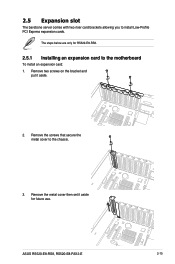
ASUS RS520-E8-RS8, RS520-E8-RS12-E 2-15 Remove two screws on the bracket and put it aside for RS520-E8-RS8. 2.5.1 Installing an expansion card to install Low-Profile PCI Express expansion cards. 2.5 Expansion slot The barebone server comes with two riser card brackets allowing you to the motherboard To install an expansion card: 1. Remove the metal cover then set it aside. 2. The steps below are only for future use. Remove the screws that secure the metal cover to the chassis. 3.
ASUS RS520-E8-RS8, RS520-E8-RS12-E 2-15 Remove two screws on the bracket and put it aside for RS520-E8-RS8. 2.5.1 Installing an expansion card to install Low-Profile PCI Express expansion cards. 2.5 Expansion slot The barebone server comes with two riser card brackets allowing you to the motherboard To install an expansion card: 1. Remove the metal cover then set it aside. 2. The steps below are only for future use. Remove the screws that secure the metal cover to the chassis. 3.
User Guide
Page 41
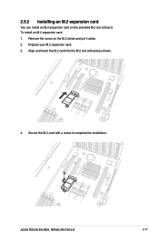
2.5.2 Installing an M.2 expansion card You can install an M.2 expansion card on the M.2 sicket and put it aside. 2. ASUS RS520-E8-RS8, RS520-E8-RS12-E 2-17 Prepare your M.2 expansion card. 3. Align and insert the M.2 card into the M.2 slot onboard as shown. 4. Secure the M.2 card with a screw to complete the installation. Remove the screw on the provided M.2 slot onboard. To install an M.2 expansion card: 1.
2.5.2 Installing an M.2 expansion card You can install an M.2 expansion card on the M.2 sicket and put it aside. 2. ASUS RS520-E8-RS8, RS520-E8-RS12-E 2-17 Prepare your M.2 expansion card. 3. Align and insert the M.2 card into the M.2 slot onboard as shown. 4. Secure the M.2 card with a screw to complete the installation. Remove the screw on the provided M.2 slot onboard. To install an M.2 expansion card: 1.

User Guide
Page 43
Connect the signal end (black) to your exact cable. 4. Secure the Mezzanine card with the four (4) bundled screws. 5. ASUS RS520-E8-RS8, RS520-E8-RS12-E 2-19 OCP_LED1 The two ends of the signal cable are different in size and color for easy recognization. Please refer to the OCP_LED1 header on the motherboard.
Connect the signal end (black) to your exact cable. 4. Secure the Mezzanine card with the four (4) bundled screws. 5. ASUS RS520-E8-RS8, RS520-E8-RS12-E 2-19 OCP_LED1 The two ends of the signal cable are different in size and color for easy recognization. Please refer to the OCP_LED1 header on the motherboard.
User Guide
Page 45
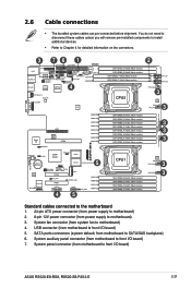
... panel connector (from power supply to front I /O board) 7. System fan connector (from motherboard to motherboard) 4. System auxiliary panel connector (from system fan to front I /O board) ASUS RS520-E8-RS8, RS520-E8-RS12-E 2-21 2.6 Cable connections • The bundled system cables are pre-connected before shipment.
... panel connector (from power supply to front I /O board) 7. System fan connector (from motherboard to motherboard) 4. System auxiliary panel connector (from system fan to front I /O board) ASUS RS520-E8-RS8, RS520-E8-RS12-E 2-21 2.6 Cable connections • The bundled system cables are pre-connected before shipment.
User Guide
Page 47
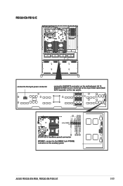
RS520-E8-RS12-E connect to the 8-pin power connector connect to SAS/SATA connector on the auxiliary panel ASUS RS520-E8-RS8, RS520-E8-RS12-E 2-23 BPSMB1: connect to this 8-port SAS cable (SAS/ SATA expander on the rear panel). All 12 SAS/SATA HDD can be connected to the SMB(6-1 pin FPSMB) connector on the motherboard.
RS520-E8-RS12-E connect to the 8-pin power connector connect to SAS/SATA connector on the auxiliary panel ASUS RS520-E8-RS8, RS520-E8-RS12-E 2-23 BPSMB1: connect to this 8-port SAS cable (SAS/ SATA expander on the rear panel). All 12 SAS/SATA HDD can be connected to the SMB(6-1 pin FPSMB) connector on the motherboard.
User Guide
Page 49
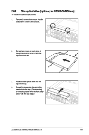
2.8.2 Slim optical drive (optional, for RS520-E8-RS8 only) To install the optional optical drive: 1. Place the slim optical drive into the bay. (The drive tray is correctly placed when its front edge aligns with the bay edge.) ASUS RS520-E8-RS8, RS520-E8-RS12-E 2-25 Secure two screws on each side of the optical drive to the chassis. 2. Ensure the expansion tray are totally inserted into the expansion bay. 4. Remove 2 screws that secure the slim optical drive cover to secure it into the expansion bracket. 3.
2.8.2 Slim optical drive (optional, for RS520-E8-RS8 only) To install the optional optical drive: 1. Place the slim optical drive into the bay. (The drive tray is correctly placed when its front edge aligns with the bay edge.) ASUS RS520-E8-RS8, RS520-E8-RS12-E 2-25 Secure two screws on each side of the optical drive to the chassis. 2. Ensure the expansion tray are totally inserted into the expansion bay. 4. Remove 2 screws that secure the slim optical drive cover to secure it into the expansion bracket. 3.
User Guide
Page 51
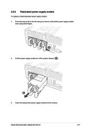
ASUS RS520-E8-RS8, RS520-E8-RS12-E 2-27 Pull the power supply module out of the system chassis ( B ). 2.8.3 Redundant power supply module To replace a failed redundant power supply module: 1. B 3. Press the secure tab to the left using your thumb, and hold the power supply module lever using other fingers. Insert the replacement power supply module into the chassis. A 2.
ASUS RS520-E8-RS8, RS520-E8-RS12-E 2-27 Pull the power supply module out of the system chassis ( B ). 2.8.3 Redundant power supply module To replace a failed redundant power supply module: 1. B 3. Press the secure tab to the left using your thumb, and hold the power supply module lever using other fingers. Insert the replacement power supply module into the chassis. A 2.
User Guide
Page 55
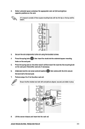
Ensure that comes with two thin lips on the rack post. 5. ASUS RS520-E8-RS8, RS520-E8-RS12-E 3-3 Secure the rail components to the rack post. 7. Select a desired space and place the appropriate rack rail (left and right) are aligned, secured, and ...
Ensure that comes with two thin lips on the rack post. 5. ASUS RS520-E8-RS8, RS520-E8-RS12-E 3-3 Secure the rail components to the rack post. 7. Select a desired space and place the appropriate rack rail (left and right) are aligned, secured, and ...


