

User Guide
Page 5
... Settings Configuration 5-35 5.6.3 Security 5-36 5.7 Exit menu 5-39 Chapter 6: RAID configuration 6.1 Setting up RAID 6-2 6.1.1 RAID definitions 6-2 6.1.2 Installing hard disk drives 6-3 6.1.3 Setting the RAID item in BIOS 6-3 6.1.4 RAID configuration utility 6-3 6.2 LSI Logic Embedded SATA RAID Setup Utility 6-4 6.2.1 Creating a RAID 0 or RAID 1 set 6-5 6.2.2 Creating a RAID 10 set 6-11 6.2.3 Adding or viewing a RAID configuration 6-15 6.2.4 Initializing the logical drives 6-18 6.2.5 Rebuilding failed drives...
... Settings Configuration 5-35 5.6.3 Security 5-36 5.7 Exit menu 5-39 Chapter 6: RAID configuration 6.1 Setting up RAID 6-2 6.1.1 RAID definitions 6-2 6.1.2 Installing hard disk drives 6-3 6.1.3 Setting the RAID item in BIOS 6-3 6.1.4 RAID configuration utility 6-3 6.2 LSI Logic Embedded SATA RAID Setup Utility 6-4 6.2.1 Creating a RAID 0 or RAID 1 set 6-5 6.2.2 Creating a RAID 10 set 6-11 6.2.3 Adding or viewing a RAID configuration 6-15 6.2.4 Initializing the logical drives 6-18 6.2.5 Rebuilding failed drives...

User Guide
Page 6
...ROM Utility 6-31 6.3.1 Creating a RAID 0 set (Stripe 6-32 6.3.2 Creating a RAID 1 set (Mirror 6-34 6.3.3 Creating a RAID 10 set (Stripe + Mirror 6-35 6.3.4 Creating a RAID 5 set (Parity 6-36 6.3.5 Deleting a RAID set 6-37 6.3.6 Resetting disks to Non-RAID 6-38 6.3.7 Exiting the Intel®... Matrix Storage Manager 6-38 6.4 Global Array Manager 6-39 Chapter 7: Driver installation 7.1 RAID driver installation 7-2 7.1.1 Creating a RAID driver disk 7-2 7.1.2 Installing the RAID controller driver 7-3 7.2 LAN driver installation 7-12 7.2.1 Windows® 2000/2003 Server 7-12 ...
...ROM Utility 6-31 6.3.1 Creating a RAID 0 set (Stripe 6-32 6.3.2 Creating a RAID 1 set (Mirror 6-34 6.3.3 Creating a RAID 10 set (Stripe + Mirror 6-35 6.3.4 Creating a RAID 5 set (Parity 6-36 6.3.5 Deleting a RAID set 6-37 6.3.6 Resetting disks to Non-RAID 6-38 6.3.7 Exiting the Intel®... Matrix Storage Manager 6-38 6.4 Global Array Manager 6-39 Chapter 7: Driver installation 7.1 RAID driver installation 7-2 7.1.1 Creating a RAID driver disk 7-2 7.1.2 Installing the RAID controller driver 7-3 7.2 LAN driver installation 7-12 7.2.1 Windows® 2000/2003 Server 7-12 ...
User Guide
Page 9
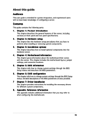
..., including sections on front panel and rear panel specifications. 2. Chapter 5: BIOS information This chapter tells how to install optional components into the barebone server. 4 . Chapter 6: RAID configuration This chapter tells how to change system settings through the BIOS Setup menus. ix
..., including sections on front panel and rear panel specifications. 2. Chapter 5: BIOS information This chapter tells how to install optional components into the barebone server. 4 . Chapter 6: RAID configuration This chapter tells how to change system settings through the BIOS Setup menus. ix

User Guide
Page 12
... Bundled CDs • RS120-E3 drivers and utilities CD • CA Anti-virus software CD 5. You may have to Chapter 7 for the following standard items. 1. ASUS R10 1U rackmount chassis with: • ASUS P5MT-R motherboard • 400 W power supply • SATA backplane (ASUS BP2LSA-R10) with 2...ASUS PCI64-EXP-X8) • Front I/O board (ASUS FPB-AR14) • Optical drive with IDE cable • 6 x system fans (3 x 56 mm; 3 x 28 mm) • 2 x hot-swap HDD trays • Pre-connected device/power cables 2. Refer to use a USB floppy drive when creating a SATA RAID...
... Bundled CDs • RS120-E3 drivers and utilities CD • CA Anti-virus software CD 5. You may have to Chapter 7 for the following standard items. 1. ASUS R10 1U rackmount chassis with: • ASUS P5MT-R motherboard • 400 W power supply • SATA backplane (ASUS BP2LSA-R10) with 2...ASUS PCI64-EXP-X8) • Front I/O board (ASUS FPB-AR14) • Optical drive with IDE cable • 6 x system fans (3 x 56 mm; 3 x 28 mm) • 2 x hot-swap HDD trays • Pre-connected device/power cables 2. Refer to use a USB floppy drive when creating a SATA RAID...

User Guide
Page 13
... Storage Manager - RAID 0, RAID 1, RAID 10, or software RAID 5 configuration using the LSI Logic Embedded SATA RAID controller Management ASUS Server Web-based Management (ASWM) Monitoring Voltage, temperature, and fan speed monitoring Automatic System Restart (ASR) feature P o w e r r e q u i r e m e n t 400 W power supply, 100V~240V, 50Hz~60Hz Dimensions 600 mm (l) x 445 mm (w) x 43.6 mm (h) ASUS RS120-E3 (PA2) 1-3 1.2 System specifications The ASUS RS120-E3 (PA2) is a 1U...
... Storage Manager - RAID 0, RAID 1, RAID 10, or software RAID 5 configuration using the LSI Logic Embedded SATA RAID controller Management ASUS Server Web-based Management (ASWM) Monitoring Voltage, temperature, and fan speed monitoring Automatic System Restart (ASR) feature P o w e r r e q u i r e m e n t 400 W power supply, 100V~240V, 50Hz~60Hz Dimensions 600 mm (l) x 445 mm (w) x 43.6 mm (h) ASUS RS120-E3 (PA2) 1-3 1.2 System specifications The ASUS RS120-E3 (PA2) is a 1U...

User Guide
Page 49
...(Blue 2-pin RESET) Page 4-9 4-9 4-10 4-11 4-11 4-12 4-12 4-13 4-14 4-14 4-15 4-15 4-16 4-17 ASUS RS120-E3 (PA2) 4-3 Serial port connector (10-1 pin COM2) 8. Gigabit LAN1 controller setting (3-pin LAN_EN1) 5. Integrated graphics controller (3-pin VGA_EN1) 7. ... REAR_FAN1/2) 6. SSI power connectors (24-pin ATXPWR1, 4-pin ATX12V1) 9. Keyboard power (3-pin KBPWR1) 4. Backplane SMBus connector (6-1 pin BPSMB1) 12. RAID controller selection (3-pin RAID_SEL1) 8. Ambient thermal sensor (2-pin TRPWR1) 13. Force BIOS recovery (3-pin RECOVERY1) Page 4-4 4-5 4-5 4-6 4-6 4-7 4-7 ...
...(Blue 2-pin RESET) Page 4-9 4-9 4-10 4-11 4-11 4-12 4-12 4-13 4-14 4-14 4-15 4-15 4-16 4-17 ASUS RS120-E3 (PA2) 4-3 Serial port connector (10-1 pin COM2) 8. Gigabit LAN1 controller setting (3-pin LAN_EN1) 5. Integrated graphics controller (3-pin VGA_EN1) 7. ... REAR_FAN1/2) 6. SSI power connectors (24-pin ATXPWR1, 4-pin ATX12V1) 9. Keyboard power (3-pin KBPWR1) 4. Backplane SMBus connector (6-1 pin BPSMB1) 12. RAID controller selection (3-pin RAID_SEL1) 8. Ambient thermal sensor (2-pin TRPWR1) 13. Force BIOS recovery (3-pin RECOVERY1) Page 4-4 4-5 4-5 4-6 4-6 4-7 4-7 ...

User Guide
Page 53
... SATA RAID Utility (default); RAID controller selection (3-pin RAID_SEL1) This jumper allows you to select the RAID configuration utility to use when you create disk arrays. otherwise, place the jumper caps to pins 2-3 to use the Intel® Matrix Storage Manager utility. ® P5MT-R P5MT-R RAID select jumper RAID_SEL1 1 2 LSI RAID ROM (Default) 2 3 INTEL RAID ROM ASUS RS120-E3 (PA2) 4-7
... SATA RAID Utility (default); RAID controller selection (3-pin RAID_SEL1) This jumper allows you to select the RAID configuration utility to use when you create disk arrays. otherwise, place the jumper caps to pins 2-3 to use the Intel® Matrix Storage Manager utility. ® P5MT-R P5MT-R RAID select jumper RAID_SEL1 1 2 LSI RAID ROM (Default) 2 3 INTEL RAID ROM ASUS RS120-E3 (PA2) 4-7

User Guide
Page 56
...Intel® ICH7R Southbridge. If you installed Serial ATA hard disk drives, you can create a RAID 0, RAID 1, RAID 10, and software RAID 5 configuration using the Intel® Matrix Storage Manager, or RAID 0, RAID 1, and RAID 10 configuration using the connectors in the BIOS to I D E mode, you can connect ...Serial ATA boot/data hard disk drives to these connectors, set to [RAID]. Serial ATA connectors (7-pin SATA1, SATA2, SATA3, SATA4) These connectors are set the Configure SATA As item in I D E mode, connect...
...Intel® ICH7R Southbridge. If you installed Serial ATA hard disk drives, you can create a RAID 0, RAID 1, RAID 10, and software RAID 5 configuration using the Intel® Matrix Storage Manager, or RAID 0, RAID 1, and RAID 10 configuration using the connectors in the BIOS to I D E mode, you can connect ...Serial ATA boot/data hard disk drives to these connectors, set to [RAID]. Serial ATA connectors (7-pin SATA1, SATA2, SATA3, SATA4) These connectors are set the Configure SATA As item in I D E mode, connect...

User Guide
Page 79
... allow you to set the ATA/IDE Configuration to [Enhanced] mode. Configure SATA As [IDE] Sets the configuration for RAID 0, RAID 1, or RAID 0+1 configuration; ASUS RS120-E3 (PA2) 5-15 Select an item then press if you want to create a RAID volume from Serial ATA hard disk drives. Configuration options: [Disabled] [Compatible] [Enhanced] The C o n f i g u r e S A T A A s and Third IDE Master/Slave...
... allow you to set the ATA/IDE Configuration to [Enhanced] mode. Configure SATA As [IDE] Sets the configuration for RAID 0, RAID 1, or RAID 0+1 configuration; ASUS RS120-E3 (PA2) 5-15 Select an item then press if you want to create a RAID volume from Serial ATA hard disk drives. Configuration options: [Disabled] [Compatible] [Enhanced] The C o n f i g u r e S A T A A s and Third IDE Master/Slave...

User Guide
Page 80
..., or both, to legacy mode. Only PATA ports are available • [PATA Pri, SATA Sec] - Legacy IDE Channels [SATA Pri, PATA Sec] Allows you to [RAID]. IDE Detect Time Out (Sec) [35] Selects the time our value (in seconds) for detecting ATA/ATAPI devices. Onboard SATA....intel.com/support/chipsets/imst/sb/CS-012305.htm The SATA controller is set to Native mode when this item is set this item to [RAID] or [AHCI]. For details on random workloads by allowing the drive to [Compatible] mode. If you want the Serial ATA hard disk drives to use...
..., or both, to legacy mode. Only PATA ports are available • [PATA Pri, SATA Sec] - Legacy IDE Channels [SATA Pri, PATA Sec] Allows you to [RAID]. IDE Detect Time Out (Sec) [35] Selects the time our value (in seconds) for detecting ATA/ATAPI devices. Onboard SATA....intel.com/support/chipsets/imst/sb/CS-012305.htm The SATA controller is set to Native mode when this item is set this item to [RAID] or [AHCI]. For details on random workloads by allowing the drive to [Compatible] mode. If you want the Serial ATA hard disk drives to use...

User Guide
Page 105
ASUS RS120-E3 (PA2) RAID configuration Chapter 6 This chapter provides instructions for setting up, creating, and configuring RAID sets using the available utilities.
ASUS RS120-E3 (PA2) RAID configuration Chapter 6 This chapter provides instructions for setting up, creating, and configuring RAID sets using the available utilities.

User Guide
Page 106
... calculated and written. Among the advantages of RAID 0, RAID 1, RAID 0+1, or software RAID 5 (Intel® Matrix Storage Manager only) configuration. 6.1.1 RAID definitions R A I n t e l® M a t r i x S t o r a g e M a n a g e r. R A I D 0 + 1 ( R A I D 5 stripes both RAID 0 and RAID 1 configurations. Use four new hard disk ... (redundancy data) having to be of three identical hard disk drives for transaction processing, relational database applications, enterprise resource planning, and other RAID performance benefits. J B O D (Spanning) stands for J u s t a B u n c h o f D i...
... calculated and written. Among the advantages of RAID 0, RAID 1, RAID 0+1, or software RAID 5 (Intel® Matrix Storage Manager only) configuration. 6.1.1 RAID definitions R A I n t e l® M a t r i x S t o r a g e M a n a g e r. R A I D 0 + 1 ( R A I D 5 stripes both RAID 0 and RAID 1 configurations. Use four new hard disk ... (redundancy data) having to be of three identical hard disk drives for transaction processing, relational database applications, enterprise resource planning, and other RAID performance benefits. J B O D (Spanning) stands for J u s t a B u n c h o f D i...

User Guide
Page 107
... of the same model and capacity when creating a disk array. 6.1.3 Setting the RAID item in BIOS You must set the RAID item in the BIOS Setup before you can create a RAID set . Save your changes, then exit the BIOS Setup. ASUS RS120-E3 (PA2) 6-3 By default, the SATA hard disk drives are connected to the SATA connectors...
... of the same model and capacity when creating a disk array. 6.1.3 Setting the RAID item in BIOS You must set the RAID item in the BIOS Setup before you can create a RAID set . Save your changes, then exit the BIOS Setup. ASUS RS120-E3 (PA2) 6-3 By default, the SATA hard disk drives are connected to the SATA connectors...
User Guide
Page 108
... Utility allows you to navigate through the setup menu options or execute commands. During POST, the LSI Logic Embedded SATA RAID Setup Utility automatically detects the installed SATA hard disk drives and displays any existing RAID set (s) from the M a n a g e m e n t M e n u, then press . The utility main window appears... hard disk drives supported by the motherboard ICH7R Southbridge chip. Turn on the next page. Use the arrow keys to create RAID 0, RAID 1, or RAID 10 set (s). At the bottom of the screen is enabled. 3. The keys on the legend box vary according to the...
... Utility allows you to navigate through the setup menu options or execute commands. During POST, the LSI Logic Embedded SATA RAID Setup Utility automatically detects the installed SATA hard disk drives and displays any existing RAID set (s) from the M a n a g e m e n t M e n u, then press . The utility main window appears... hard disk drives supported by the motherboard ICH7R Southbridge chip. Turn on the next page. Use the arrow keys to create RAID 0, RAID 1, or RAID 10 set (s). At the bottom of the screen is enabled. 3. The keys on the legend box vary according to the...
User Guide
Page 109
ASUS RS120-E3 (PA2) 6-5 In E a s y C o n f i g u r a t i o n, the logical drive parameters are set size and stripe size (RAID 1 only). In N e w C o n f i g u r a t i o n, you manually set the logical drive parameters and assign the set automatically including the size and stripe size (RAID 1 only). Use the arrow keys to create a RAID 0 or RAID 1 set using two types of a created RAID set 6.2.1 Creating a RAID 0 or RAID 1 set The LSI...
ASUS RS120-E3 (PA2) 6-5 In E a s y C o n f i g u r a t i o n, the logical drive parameters are set size and stripe size (RAID 1 only). In N e w C o n f i g u r a t i o n, you manually set the logical drive parameters and assign the set automatically including the size and stripe size (RAID 1 only). Use the arrow keys to create a RAID 0 or RAID 1 set using two types of a created RAID set 6.2.1 Creating a RAID 0 or RAID 1 set The LSI...

User Guide
Page 110
When selected, the drive indicator changes from R E A D Y to the SATA ports. The A R R A Y S E L E C T I O N M E N U displays the available drives connected to ONLIN A[X]-[Y], where X is the array number, and Y is the drive number. Select all the drives required for the RAID set , then press . The configurable array appears on screen. 6-6 Chapter 6: RAID configuration The information of the selected hard disk drive displays at the bottom of the screen. 4. Select the drives you want to include in the RAID set , then press . 3.
When selected, the drive indicator changes from R E A D Y to the SATA ports. The A R R A Y S E L E C T I O N M E N U displays the available drives connected to ONLIN A[X]-[Y], where X is the array number, and Y is the drive number. Select all the drives required for the RAID set , then press . The configurable array appears on screen. 6-6 Chapter 6: RAID configuration The information of the selected hard disk drive displays at the bottom of the screen. 4. Select the drives you want to include in the RAID set , then press . 3.
User Guide
Page 112
... Select R A I D from the L o g i c a l D r i v e menu, then press . 6. You need at least two identical hard disk drives when creating a RAID 1 set , proceed to step 10. 9. Key-in the stripe size, then press . For multimedia computer systems used mainly for audio and video editing, we recommend ...
... Select R A I D from the L o g i c a l D r i v e menu, then press . 6. You need at least two identical hard disk drives when creating a RAID 1 set , proceed to step 10. 9. Key-in the stripe size, then press . For multimedia computer systems used mainly for audio and video editing, we recommend ...
User Guide
Page 114
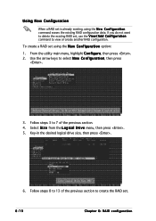
... is already existing, using the N e w C o n f i g u r a t i o n option: 1. If you do not want to 13 of the previous section. 4. To create a RAID set using the N e w C o n f i g u r a t i o n command erases the existing RAID configuration data. From the utility main menu, highlight C o n f i g u r e, then press . 2. Select S i z e from the L o g i c a l D r i v e menu, then press . 5. Follow steps 3 to 7 of the previous section to...
... is already existing, using the N e w C o n f i g u r a t i o n option: 1. If you do not want to 13 of the previous section. 4. To create a RAID set using the N e w C o n f i g u r a t i o n command erases the existing RAID configuration data. From the utility main menu, highlight C o n f i g u r e, then press . 2. Select S i z e from the L o g i c a l D r i v e menu, then press . 5. Follow steps 3 to 7 of the previous section to...

User Guide
Page 115
... Easy Configuration, then press . 3. ASUS RS120-E3 (PA2) 6-11 Use the arrow keys to ONLIN A[X]-[Y], where X is the array number, and Y is the drive number. The information of the selected hard disk drive displays at the bottom of the screen. The A R R A Y S E L E C T I O N M E N U displays the available drives connected to include in the RAID set, then press . Select...
... Easy Configuration, then press . 3. ASUS RS120-E3 (PA2) 6-11 Use the arrow keys to ONLIN A[X]-[Y], where X is the array number, and Y is the drive number. The information of the selected hard disk drive displays at the bottom of the screen. The A R R A Y S E L E C T I O N M E N U displays the available drives connected to include in the RAID set, then press . Select...

User Guide
Page 116
4. Press , select the configurable array, then press . The logical drive information appears including a Logical Drive menu that allows you to change the logical drive parameters. 6-12 Chapter 6: RAID configuration Select all the drives required for the RAID 10 set, then press . The configurable array appears on screen. 5.
4. Press , select the configurable array, then press . The logical drive information appears including a Logical Drive menu that allows you to change the logical drive parameters. 6-12 Chapter 6: RAID configuration Select all the drives required for the RAID 10 set, then press . The configurable array appears on screen. 5.