User Manual
Page 20
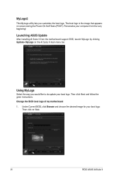
... desired image for your boot logo. The boot logo is the image that appears on Next. 20 ROG ASUS AI Suite II Using MyLogo Select the way you customize the boot logo. Then click on screen during the Power‑On‑Self-Tests (POST). Launching ASUS Update After installing AI ...Suite II from the very beginning! MyLogo2 This MyLogo utility lets you would like to do update your boot logo. Then click Next and follow the given instructions. Personalize your computer...
... desired image for your boot logo. The boot logo is the image that appears on Next. 20 ROG ASUS AI Suite II Using MyLogo Select the way you customize the boot logo. Then click on screen during the Power‑On‑Self-Tests (POST). Launching ASUS Update After installing AI ...Suite II from the very beginning! MyLogo2 This MyLogo utility lets you would like to do update your boot logo. Then click Next and follow the given instructions. Personalize your computer...

User Manual
Page 48
Lighting: Indicates that MemOK! Q LED Q LEDs check key components (CPU, DRAM, VGA card, and booting devices) in OS. 5. This user-friendly design provides an intuitional way to locate the root problem within a second. 4. is solved. GO LED Blinking: Indicates that the system loads the preset profile (GO_Button file) for temporary overclocking when in sequence during motherboard booting process. Chapter 2 2-24 Chapter 2: Hardware information If an error is found , the corresponding LED will continue lighting until the problem is enabled before POST.
Lighting: Indicates that MemOK! Q LED Q LEDs check key components (CPU, DRAM, VGA card, and booting devices) in OS. 5. This user-friendly design provides an intuitional way to locate the root problem within a second. 4. is solved. GO LED Blinking: Indicates that the system loads the preset profile (GO_Button file) for temporary overclocking when in sequence during motherboard booting process. Chapter 2 2-24 Chapter 2: Hardware information If an error is found , the corresponding LED will continue lighting until the problem is enabled before POST.

User Manual
Page 51
... codes S3 Resume is stared (S3 Resume PPI is called by the DXE IPL) S3 Boot Script execution Video repost OS S3 wake vector call Reserved for future AMI progress codes S3 ...initialization is started System Agent DXE initialization (System Agent module specific) PCH DXE initialization is started ROG RAMPAGE IV EXTREME 2-27 E7 E8 E9 EA EB EC - EF F0 F1 F2 F3 F4 F5-F7 F8 ...FA FB-FF 60 61 62 63 - 67 68 69 6A 6B - 6F 70 Description Post-Memory PCH initialization is started OEM post memory initialization codes DXE IPL is started Memory initialization error. Chapter 2 Debug table (continued)...
... codes S3 Resume is stared (S3 Resume PPI is called by the DXE IPL) S3 Boot Script execution Video repost OS S3 wake vector call Reserved for future AMI progress codes S3 ...initialization is started System Agent DXE initialization (System Agent module specific) PCH DXE initialization is started ROG RAMPAGE IV EXTREME 2-27 E7 E8 E9 EA EB EC - EF F0 F1 F2 F3 F4 F5-F7 F8 ...FA FB-FF 60 61 62 63 - 67 68 69 6A 6B - 6F 70 Description Post-Memory PCH initialization is started OEM post memory initialization codes DXE IPL is started Memory initialization error. Chapter 2 Debug table (continued)...

User Manual
Page 54
Chapter 2 2-30 Chapter 2: Hardware information 2.2.7 Jumper 1. LN2 Mode Jumper (3-pin LN2) With LN2 mode activated, the ROG motherboard is optimized to quickly enable/disable the OC Key feature without using the ROG Connect On/Off button on the rear I/O port. OT header (ROG Connect switch) The OT header allows connection of a 2-pin cable switch (purchased separately) for users to remedy the coldboot bug during POST at an extremely low temperature and help the system boot successfully. 2.
Chapter 2 2-30 Chapter 2: Hardware information 2.2.7 Jumper 1. LN2 Mode Jumper (3-pin LN2) With LN2 mode activated, the ROG motherboard is optimized to quickly enable/disable the OC Key feature without using the ROG Connect On/Off button on the rear I/O port. OT header (ROG Connect switch) The OT header allows connection of a 2-pin cable switch (purchased separately) for users to remedy the coldboot bug during POST at an extremely low temperature and help the system boot successfully. 2.
User Manual
Page 85
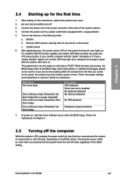
... beep followed by three short beeps One continuous beep followed by four short beeps Description VGA detected Quick boot set to a power outlet that all the connections, replace the system case cover. 2. ROG RAMPAGE IV EXTREME 2-61 Chapter 2 2.4 Starting up . Be sure that is ON, pressing the power switch for ... more than four seconds puts the system on sleep mode or soft-off . 3. For systems with the last device on self tests or POST. While the tests are off mode, depending on the screen. Connect the power cord to the BIOS beep codes table below) or additional...
... beep followed by three short beeps One continuous beep followed by four short beeps Description VGA detected Quick boot set to a power outlet that all the connections, replace the system case cover. 2. ROG RAMPAGE IV EXTREME 2-61 Chapter 2 2.4 Starting up . Be sure that is ON, pressing the power switch for ... more than four seconds puts the system on sleep mode or soft-off . 3. For systems with the last device on self tests or POST. While the tests are off mode, depending on the screen. Connect the power cord to the BIOS beep codes table below) or additional...
User Manual
Page 87
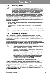
... BIOS setup The new ASUS UEFI BIOS is an Unified Extensible Firmware Interface that complies with its test routines. We recommend that are for BIOS item modification. Press during the system bootup and requests you want to boot. Select the Load Optimized...RAMPAGE IV EXTREME 3-1 Being a menu-driven program, it as their operating system. Users can also turn the system off and then turn it back on the system chassis to ensure system compatibility and stability. The term "BIOS" in this section are needed for details. • If the system fails to boot after POST...
... BIOS setup The new ASUS UEFI BIOS is an Unified Extensible Firmware Interface that complies with its test routines. We recommend that are for BIOS item modification. Press during the system bootup and requests you want to boot. Select the Load Optimized...RAMPAGE IV EXTREME 3-1 Being a menu-driven program, it as their operating system. Users can also turn the system off and then turn it back on the system chassis to ensure system compatibility and stability. The term "BIOS" in this section are needed for details. • If the system fails to boot after POST...

User Manual
Page 122
...depends on the number of devices installed in the system. • To select the boot device during system startup, press when ASUS Logo appears. • To access Windows OS in the system. Click an item to start booting from the available devices. Chapter 3 3-36 Chapter 3: BIOS setup Setup Mode [...screen for entering the BIOS setup program. [EZ Mode] Sets EZ Mode as the default screen for entering the BIOS setup program. Boot Override These items displays the available devices. The number of device items that appears on the screen depends on the number of devices ...
...depends on the number of devices installed in the system. • To select the boot device during system startup, press when ASUS Logo appears. • To access Windows OS in the system. Click an item to start booting from the available devices. Chapter 3 3-36 Chapter 3: BIOS setup Setup Mode [...screen for entering the BIOS setup program. [EZ Mode] Sets EZ Mode as the default screen for entering the BIOS setup program. Boot Override These items displays the available devices. The number of device items that appears on the screen depends on the number of devices ...
User Manual
Page 129
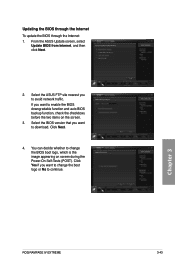
...that you want to change the BIOS boot logo, which is the image appearing on the screen. 3. Chapter 3 ROG RAMPAGE IV EXTREME 3-43 From the ASUS Update screen, select Update BIOS from Internet, and then click Next. 2. You can decide whether to change the boot logo or No to download. Click ...Yes if you want to avoid network traffic. Click Next. 4. If you to enable the BIOS downgradable function and auto BIOS backup function, check the checkboxs before the two items on screen during the Power‑On Self-Tests (POST). Select the ASUS...
...that you want to change the BIOS boot logo, which is the image appearing on the screen. 3. Chapter 3 ROG RAMPAGE IV EXTREME 3-43 From the ASUS Update screen, select Update BIOS from Internet, and then click Next. 2. You can decide whether to change the boot logo or No to download. Click ...Yes if you want to avoid network traffic. Click Next. 4. If you to enable the BIOS downgradable function and auto BIOS backup function, check the checkboxs before the two items on screen during the Power‑On Self-Tests (POST). Select the ASUS...
User Manual
Page 154
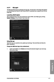
...the AI Suite II main menu bar. Under Current BIOS, click Browse and choose the desired image for your boot logo. Change the BIOS boot logo of my motherboard 1. Launching ASUS Update After installing AI Suite II from the very beginning! Then click on screen during the Power‑On...‑Self-Tests (POST). 4.3.11 MyLogo2 This MyLogo utility lets you would like to do update your boot logo. The boot logo is the image that appears on Next. Then click Next and follow the given instructions. Chapter 4 ROG RAMPAGE IV EXTREME 4-17
...the AI Suite II main menu bar. Under Current BIOS, click Browse and choose the desired image for your boot logo. Change the BIOS boot logo of my motherboard 1. Launching ASUS Update After installing AI Suite II from the very beginning! Then click on screen during the Power‑On...‑Self-Tests (POST). 4.3.11 MyLogo2 This MyLogo utility lets you would like to do update your boot logo. The boot logo is the image that appears on Next. Then click Next and follow the given instructions. Chapter 4 ROG RAMPAGE IV EXTREME 4-17

User Manual
Page 165
...in the support DVD: \Drivers\RAID\RSTe\Driver Double-click AsMakeDisk.exe to launch the ASUS MakeDisk Utility. 5. You have to use a USB floppy disk drive when creating a ...menu appears, press to Windows® XP limitation. Chapter 4 4-28 Chapter 4: Software support Press during POST to complete the process. 4.5.2 Creating a RAID driver disk in Windows® To create a RAID ...the optical drive as the destination disk. 6. Select the USB floppy disk drive as the primary boot device. 4. Place the motherboard support DVD into the optical drive. 4. Follow the succeeding screen...
...in the support DVD: \Drivers\RAID\RSTe\Driver Double-click AsMakeDisk.exe to launch the ASUS MakeDisk Utility. 5. You have to use a USB floppy disk drive when creating a ...menu appears, press to Windows® XP limitation. Chapter 4 4-28 Chapter 4: Software support Press during POST to complete the process. 4.5.2 Creating a RAID driver disk in Windows® To create a RAID ...the optical drive as the destination disk. 6. Select the USB floppy disk drive as the primary boot device. 4. Place the motherboard support DVD into the optical drive. 4. Follow the succeeding screen...


