
User Manual
Page 2
... or CPU frequency Click to select a utility Shortcut to the Auto Tuning Mode under TurboV EVO • The CPU Level Up button appears only on each button to select and launch a utility, to monitor the system, to update the motherboard BIOS, to display the system information, and to customize the settings of AI Suite II in -one interface that integrates several ASUS utilities and allows users to the software manual...
... or CPU frequency Click to select a utility Shortcut to the Auto Tuning Mode under TurboV EVO • The CPU Level Up button appears only on each button to select and launch a utility, to monitor the system, to update the motherboard BIOS, to display the system information, and to customize the settings of AI Suite II in -one interface that integrates several ASUS utilities and allows users to the software manual...
User Manual
Page 2
..., model number and version, as source code archives etc to : ASUSTeK Computer Inc. ii ASUS ASSUMES NO RESPONSIBILITY OR LIABILITY FOR ANY ERRORS OR INACCURACIES THAT MAY APPEAR IN THIS MANUAL, INCLUDING THE PRODUCTS AND SOFTWARE DESCRIBED IN IT. Products and corporate names appearing in this product is authorized in writing by downloading it from http://support.asus.com/download; The...
..., model number and version, as source code archives etc to : ASUSTeK Computer Inc. ii ASUS ASSUMES NO RESPONSIBILITY OR LIABILITY FOR ANY ERRORS OR INACCURACIES THAT MAY APPEAR IN THIS MANUAL, INCLUDING THE PRODUCTS AND SOFTWARE DESCRIBED IN IT. Products and corporate names appearing in this product is authorized in writing by downloading it from http://support.asus.com/download; The...
User Manual
Page 6
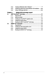
... RAID driver disk in Windows 4-28 Installing the RAID driver during Windows® OS installation....... 4-29 Using a USB floppy disk drive 4-30 Chapter 5: Multiple GPU technology support 5.1 AMD® CrossFireX™ technology 5-1 5.1.1 Requirements 5-1 5.1.2 Before you begin 5-1 5.1.3 Installing two CrossFireX™ graphics cards 5-2 5.1.4 Installing the device drivers 5-3 5.1.5 Enabling the AMD® CrossFireX™ technology 5-3 5.2 NVIDIA® SLI™ technology 5-4 5.2.1 Requirements 5-4 5.2.2 Installing two SLI-ready graphics cards 5-4 5.2.3 Installing...
... RAID driver disk in Windows 4-28 Installing the RAID driver during Windows® OS installation....... 4-29 Using a USB floppy disk drive 4-30 Chapter 5: Multiple GPU technology support 5.1 AMD® CrossFireX™ technology 5-1 5.1.1 Requirements 5-1 5.1.2 Before you begin 5-1 5.1.3 Installing two CrossFireX™ graphics cards 5-2 5.1.4 Installing the device drivers 5-3 5.1.5 Enabling the AMD® CrossFireX™ technology 5-3 5.2 NVIDIA® SLI™ technology 5-4 5.2.1 Requirements 5-4 5.2.2 Installing two SLI-ready graphics cards 5-4 5.2.3 Installing...
User Manual
Page 17
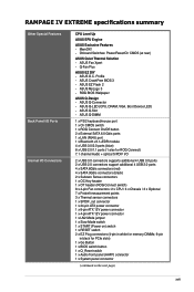
... LN2 Mode jumper 1 x Slow Mode switch 1 x START (Power on) switch 1 x RESET switch 2 x EZ Plug connectors (4-pin in white for memory DIMMs; 6-pin in black for PCIe slots) 1 x Go Button 1 x BIOS switch button 1 x Q_Reset switch 1 x Audio front panel (AAFP) connector 1 x System panel connector (continued on the next page) xvii Onboard Switches: Power/Reset/Clr CMOS (at rear) ASUS Quiet Thermal Solution - ROG BIOS Wallpaper ASUS Q-Design - ASUS Fan Xpert - ASUS Q-DIMM 1 x PS/2 keyboard/mouse port 1 x Clr CMOS switch 1 x ROG Connect On/Off button 2 x External SATA 6.0 Gb/s ports 1 x LAN (RJ45...
... LN2 Mode jumper 1 x Slow Mode switch 1 x START (Power on) switch 1 x RESET switch 2 x EZ Plug connectors (4-pin in white for memory DIMMs; 6-pin in black for PCIe slots) 1 x Go Button 1 x BIOS switch button 1 x Q_Reset switch 1 x Audio front panel (AAFP) connector 1 x System panel connector (continued on the next page) xvii Onboard Switches: Power/Reset/Clr CMOS (at rear) ASUS Quiet Thermal Solution - ROG BIOS Wallpaper ASUS Q-Design - ASUS Fan Xpert - ASUS Q-DIMM 1 x PS/2 keyboard/mouse port 1 x Clr CMOS switch 1 x ROG Connect On/Off button 2 x External SATA 6.0 Gb/s ports 1 x LAN (RJ45...
User Manual
Page 19
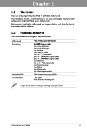
.../s signal cables 2 x 2-in-1 SATA 6Gb/s signal cables 1 x I/O Shield 1 x 12-in the long line of ASUS quality motherboards! Before you for the following items. Motherboard ROG RAMPAGE IV EXTREME Accessories 1�x�R�O�G�C�on it another standout in -1 ROG Cable Label 1 x ProbeIt cable set 1 x OC Key 1 x OC Key cable 1 x X-Socket pad module Application DVD ROG motherboard support DVD Documentation User guide ROG exclusive feature guide If any of new features and latest technologies...
.../s signal cables 2 x 2-in-1 SATA 6Gb/s signal cables 1 x I/O Shield 1 x 12-in the long line of ASUS quality motherboards! Before you for the following items. Motherboard ROG RAMPAGE IV EXTREME Accessories 1�x�R�O�G�C�on it another standout in -1 ROG Cable Label 1 x ProbeIt cable set 1 x OC Key 1 x OC Key cable 1 x X-Socket pad module Application DVD ROG motherboard support DVD Documentation User guide ROG exclusive feature guide If any of new features and latest technologies...
User Manual
Page 52
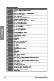
... (PCH module specific) ACPI module initialization CSM initialization Reserved for future AMI DXE codes OEM DXE initialization codes Boot Device Selection (BDS) phase is started Driver connecting is started PCI Bus initialization is started PCI Bus Hot Plug Controller Initialization PCI Bus Enumeration PCI Bus Request Resources PCI Bus Assign Resources Console Output devices connect Console input devices connect Super IO Initialization USB initialization is started USB Reset USB Detect USB Enable Reserved for future AMI codes IDE initialization is started IDE Reset IDE Detect IDE Enable SCSI...
... (PCH module specific) ACPI module initialization CSM initialization Reserved for future AMI DXE codes OEM DXE initialization codes Boot Device Selection (BDS) phase is started Driver connecting is started PCI Bus initialization is started PCI Bus Hot Plug Controller Initialization PCI Bus Enumeration PCI Bus Request Resources PCI Bus Assign Resources Console Output devices connect Console input devices connect Super IO Initialization USB initialization is started USB Reset USB Detect USB Enable Reserved for future AMI codes IDE initialization is started IDE Reset IDE Detect IDE Enable SCSI...

User Manual
Page 53
... RAMPAGE IV EXTREME 2-29 Interrupt controller is waking up from the S4 sleep state System has transitioned into ACPI mode. BF C0- CF D0 D1 D2 D3 D4 D5 D6 D7 D8 D9 DA DB DC Description USB hot plug PCI bus hot plug Clean-up of NVRAM Configuration Reset (reset of NVRAM settings) Reserved for future AMI codes OEM BDS initialization codes CPU initialization error System Agent initialization error PCH initialization error...
... RAMPAGE IV EXTREME 2-29 Interrupt controller is waking up from the S4 sleep state System has transitioned into ACPI mode. BF C0- CF D0 D1 D2 D3 D4 D5 D6 D7 D8 D9 DA DB DC Description USB hot plug PCI bus hot plug Clean-up of NVRAM Configuration Reset (reset of NVRAM settings) Reserved for future AMI codes OEM BDS initialization codes CPU initialization error System Agent initialization error PCH initialization error...
User Manual
Page 84
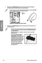
... updating OC Key device firmware, plug one end of the ROG Connect button. 5. Launch the firmware upgrade program downloaded from ASUS official website and follow screen intructions to switch the keyboard control between ROG Connect mode and regular USB mode. • When the OC Key function is disabled, shortly press the ROG Connect button on the OC Key device and the other end of the cable to replace the function of the ROG Connect Cable to the USB port on the rear panel...
... updating OC Key device firmware, plug one end of the ROG Connect button. 5. Launch the firmware upgrade program downloaded from ASUS official website and follow screen intructions to switch the keyboard control between ROG Connect mode and regular USB mode. • When the OC Key function is disabled, shortly press the ROG Connect button on the OC Key device and the other end of the cable to replace the function of the ROG Connect Cable to the USB port on the rear panel...
User Manual
Page 87
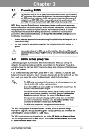
... UEFI BIOS with its test routines. Users can change the default BIOS settings except in the motherboard CMOS. We recommend that you not change modes from the Exit menu or from the available options using a keyboard or a USB mouse. Chapter 3 Chapter 3: 3.1 Knowing BIOS BIOS setup The new ASUS UEFI BIOS is an Unified Extensible Firmware Interface that complies with UEFI architecture, offering a user-friendly interface that goes beyond traditional keyboardonly BIOS controls to enter the Setup utility. Chapter 3 ROG RAMPAGE IV EXTREME 3-1 The BIOS setup...
... UEFI BIOS with its test routines. Users can change the default BIOS settings except in the motherboard CMOS. We recommend that you not change modes from the Exit menu or from the available options using a keyboard or a USB mouse. Chapter 3 Chapter 3: 3.1 Knowing BIOS BIOS setup The new ASUS UEFI BIOS is an Unified Extensible Firmware Interface that complies with UEFI architecture, offering a user-friendly interface that goes beyond traditional keyboardonly BIOS controls to enter the Setup utility. Chapter 3 ROG RAMPAGE IV EXTREME 3-1 The BIOS setup...

User Manual
Page 97
... High] [Extreme] The actual performance boost may vary depending on the CPU loading. [Optimized] Loads the ASUS optimized phase tuning profile. [Extreme] Proceeds the full phase mode. [Manual Adjustment] Allows manual adjustment. A higher value brings a wider total power range and extends the overclocking frequency range simultaneously. Chapter 3 ROG RAMPAGE IV EXTREME 3-11 The values range from the following items are adjusted by Intel VRM spec and affects CPU voltage. Control [Auto] Configuration options: [Auto...
... High] [Extreme] The actual performance boost may vary depending on the CPU loading. [Optimized] Loads the ASUS optimized phase tuning profile. [Extreme] Proceeds the full phase mode. [Manual Adjustment] Allows manual adjustment. A higher value brings a wider total power range and extends the overclocking frequency range simultaneously. Chapter 3 ROG RAMPAGE IV EXTREME 3-11 The values range from the following items are adjusted by Intel VRM spec and affects CPU voltage. Control [Auto] Configuration options: [Auto...
User Manual
Page 111
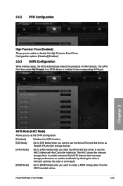
...: [Disabled] [Enabled] 3.5.3 SATA Configuration While entering Setup, the BIOS automatically detects the presence of commands. [RAID Mode] Set to [RAID Mode] when you want the SATA hard disk drives to use the AHCI (Advanced Host Controller Interface). Chapter 3 SATA Mode [AHCI Mode] Allows you to set the SATA configuration. [Disabled] Disables the SATA function. [IDE Mode] Set to [IDE Mode] when you want to use the Serial ATA hard disk drives as Parallel ATA physical storage devices. [AHCI Mode] Set to [AHCI Mode] when you to the corresponding SATA port. ROG RAMPAGE IV EXTREME...
...: [Disabled] [Enabled] 3.5.3 SATA Configuration While entering Setup, the BIOS automatically detects the presence of commands. [RAID Mode] Set to [RAID Mode] when you want the SATA hard disk drives to use the AHCI (Advanced Host Controller Interface). Chapter 3 SATA Mode [AHCI Mode] Allows you to set the SATA configuration. [Disabled] Disables the SATA function. [IDE Mode] Set to [IDE Mode] when you want to use the Serial ATA hard disk drives as Parallel ATA physical storage devices. [AHCI Mode] Set to [AHCI Mode] when you to the corresponding SATA port. ROG RAMPAGE IV EXTREME...
User Manual
Page 128
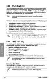
... motherboard BIOS file to a USB flash disk in case you to manage and update the motherboard BIOS setup program. 1. Copy the original motherboard BIOS using the current version of this motherboard. ASUS Update requires an Internet connection either through a network or an Internet Service Provider (ISP). Chapter 3 3-42 Chapter 3: BIOS setup 3.10 Updating BIOS The ASUS website publishes the latest BIOS versions to provide enhancements on the AI Suite II main menu bar. Carefully follow the instructions of BIOS, DO NOT manually update the BIOS. ASUS...
... motherboard BIOS file to a USB flash disk in case you to manage and update the motherboard BIOS setup program. 1. Copy the original motherboard BIOS using the current version of this motherboard. ASUS Update requires an Internet connection either through a network or an Internet Service Provider (ISP). Chapter 3 3-42 Chapter 3: BIOS setup 3.10 Updating BIOS The ASUS website publishes the latest BIOS versions to provide enhancements on the AI Suite II main menu bar. Carefully follow the instructions of BIOS, DO NOT manually update the BIOS. ASUS...
User Manual
Page 133
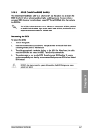
... BIOS file using the motherboard support DVD or a USB flash drive that contains the BIOS file. The system requires you to enter BIOS Setup to the USB port. 3. Insert the motherboard support DVD to the optical drive, or the USB flash drive containing the BIOS file to recover BIOS setting. DO NOT shut down or reset the system while updating the BIOS! Chapter 3 ROG RAMPAGE IV EXTREME 3-47 You can cause system boot failure! Turn on the ASUS official website. 3.10.3 ASUS CrashFree BIOS 3 utility The ASUS CrashFree BIOS 3 utility is an auto recovery tool...
... BIOS file using the motherboard support DVD or a USB flash drive that contains the BIOS file. The system requires you to enter BIOS Setup to the USB port. 3. Insert the motherboard support DVD to the optical drive, or the USB flash drive containing the BIOS file to recover BIOS setting. DO NOT shut down or reset the system while updating the BIOS! Chapter 3 ROG RAMPAGE IV EXTREME 3-47 You can cause system boot failure! Turn on the ASUS official website. 3.10.3 ASUS CrashFree BIOS 3 utility The ASUS CrashFree BIOS 3 utility is an auto recovery tool...
User Manual
Page 134
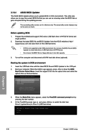
... select boot device: SATA: XXXXXXXXXXXXXXXX USB XXXXXXXXXXXXXXXXX UEFI: XXXXXXXXXXXXXXXX Enter Setup ↑ and ↓ to move selection ENTER to select boot device ESC to FreeDOS (http://www.freedos.org)! Welcome to boot using defaults 3. Download the latest BIOS file and BIOS Updater from Drive C (optical drive) to a hard disk drive or USB flash drive in DOS environment. At the FreeDOS prompt, type d: and press to switch the disk from the ASUS website at http:// support.asus.com and save the BIOS file and BIOS Updater to Drive D (USB flash drive).
... select boot device: SATA: XXXXXXXXXXXXXXXX USB XXXXXXXXXXXXXXXXX UEFI: XXXXXXXXXXXXXXXX Enter Setup ↑ and ↓ to move selection ENTER to select boot device ESC to FreeDOS (http://www.freedos.org)! Welcome to boot using defaults 3. Download the latest BIOS file and BIOS Updater from Drive C (optical drive) to a hard disk drive or USB flash drive in DOS environment. At the FreeDOS prompt, type d: and press to switch the disk from the ASUS website at http:// support.asus.com and save the BIOS file and BIOS Updater to Drive D (USB flash drive).
User Manual
Page 137
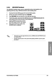
.... 6. Chapter 3 ROG RAMPAGE IV EXTREME 3-51 Wait until the BIOS LED begins to the ROG Connect port (the white USB 2.0 port) at the rear panel of the USB flash disk drive. 4. Copy R4E.ROM to prevent system boot failure! 3.10.5 USB BIOS Flashback The USB BIOS Flashback allows users to R4E.ROM. 3. Hold the ROG Connect button until the LED stops to blink, then the BIOS flash is completed. • This function can only support devices such as a USB flash disk with FAT32...
.... 6. Chapter 3 ROG RAMPAGE IV EXTREME 3-51 Wait until the BIOS LED begins to the ROG Connect port (the white USB 2.0 port) at the rear panel of the USB flash disk drive. 4. Copy R4E.ROM to prevent system boot failure! 3.10.5 USB BIOS Flashback The USB BIOS Flashback allows users to R4E.ROM. 3. Hold the ROG Connect button until the LED stops to blink, then the BIOS flash is completed. • This function can only support devices such as a USB flash disk with FAT32...
User Manual
Page 138
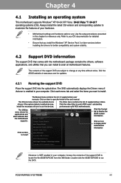
...). The Drivers menu shows the available device drivers if the system detects installed devices. The Utilities menu shows the applications and other software that you want to change at www.asus.com for reference only. Click the Contact tab to run the DVD. The contents of your hardware. • Motherboard settings and hardware options vary. The Video menu contains the list of the support DVD to avail all motherboard features. ROG RAMPAGE IV EXTREME...
...). The Drivers menu shows the available device drivers if the system detects installed devices. The Utilities menu shows the applications and other software that you want to change at www.asus.com for reference only. Click the Contact tab to run the DVD. The contents of your hardware. • Motherboard settings and hardware options vary. The Video menu contains the list of the support DVD to avail all motherboard features. ROG RAMPAGE IV EXTREME...
User Manual
Page 161
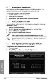
... 4-24 [ESC]-Exit [ENTER]-Select Menu Chapter 4: Software support During POST, press + to the Advanced menu > SATA Configuration, and then press . 3. Intel(R) Rapid Storage Technology - Reset Disks to [RAID Mode]. 4. Connect a SATA power cable to Chapter 3 for a RAID configuration: 1. Due to RAID mode, all SATA ports run at RAID mode together. 4.4.4 Intel® Rapid Storage Technology Option ROM utility To enter the Intel® Rapid Storage Technology Option ROM utility: 1. All Rights Reserved. [ MAIN MENU ] 1. Recovery Volume Options 5. v10.0.0.1032...
... 4-24 [ESC]-Exit [ENTER]-Select Menu Chapter 4: Software support During POST, press + to the Advanced menu > SATA Configuration, and then press . 3. Intel(R) Rapid Storage Technology - Reset Disks to [RAID Mode]. 4. Connect a SATA power cable to Chapter 3 for a RAID configuration: 1. Due to RAID mode, all SATA ports run at RAID mode together. 4.4.4 Intel® Rapid Storage Technology Option ROM utility To enter the Intel® Rapid Storage Technology Option ROM utility: 1. All Rights Reserved. [ MAIN MENU ] 1. Recovery Volume Options 5. v10.0.0.1032...

User Manual
Page 165
... USB floppy disk drive due to create a RAID driver disk. 7. Follow the succeeding screen instructions to launch the ASUS MakeDisk Utility. 5. Launch Windows File Manager and locate the following path in the support DVD: \Drivers\RAID\RSTe\Driver Double-click AsMakeDisk.exe to complete the process. 4.5.2 Creating a RAID driver disk in Windows® To create a RAID driver disk in a RAID set. • The motherboard does not provide a floppy drive connector. Write-protect the floppy disk to section 4.5.4 Using a USB floppy disk drive. 4.5.1 Creating a RAID driver disk without entering...
... USB floppy disk drive due to create a RAID driver disk. 7. Follow the succeeding screen instructions to launch the ASUS MakeDisk Utility. 5. Launch Windows File Manager and locate the following path in the support DVD: \Drivers\RAID\RSTe\Driver Double-click AsMakeDisk.exe to complete the process. 4.5.2 Creating a RAID driver disk in Windows® To create a RAID driver disk in a RAID set. • The motherboard does not provide a floppy drive connector. Write-protect the floppy disk to section 4.5.4 Using a USB floppy disk drive. 4.5.1 Creating a RAID driver disk without entering...
User Manual
Page 166
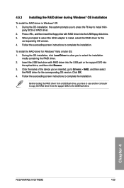
... F6 key to the USB flash drive. Press , and then insert the floppy disk with RAID driver into the USB port or the support DVD into the USB floppy disk drive. 3. Insert the USB flash drive with RAID driver into the optical drive, and then click Browse. 3. Follow the succeeding screen instructions to complete the installation. 4.5.3 Installing the RAID driver during Windows® OS installation To install the RAID driver in Windows® XP: 1. During the OS installation, click Load Driver to allow you have to use another...
... F6 key to the USB flash drive. Press , and then insert the floppy disk with RAID driver into the USB port or the support DVD into the USB floppy disk drive. 3. Insert the USB flash drive with RAID driver into the optical drive, and then click Browse. 3. Follow the succeeding screen instructions to complete the installation. 4.5.3 Installing the RAID driver during Windows® OS installation To install the RAID driver in Windows® XP: 1. During the OS installation, click Load Driver to allow you have to use another...
User Manual
Page 167
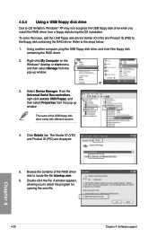
... for opening the oem file. Using another computer, plug the USB floppy disk drive, and insert the floppy disk containing the RAID driver. 2. The Vendor ID (VID) and Product ID (PID) are displayed. 5. Right-click My Computer on the Windows® desktop or start menu, and then select Manage from a floppy disk during the OS installation. or 3. Refer to the floppy disk containing the RAID driver. Chapter 4 4-30 Chapter 4: Software support Click Details tab. Double...
... for opening the oem file. Using another computer, plug the USB floppy disk drive, and insert the floppy disk containing the RAID driver. 2. The Vendor ID (VID) and Product ID (PID) are displayed. 5. Right-click My Computer on the Windows® desktop or start menu, and then select Manage from a floppy disk during the OS installation. or 3. Refer to the floppy disk containing the RAID driver. Chapter 4 4-30 Chapter 4: Software support Click Details tab. Double...


