User Manual
Page 1
P8P67-M PRO Motherboard
P8P67-M PRO Motherboard
User Manual
Page 3
Contents Notices...vi Safety information vii About this guide vii P8P67-M PRO specifications summary ix Chapter 1: Product introduction 1.1 Welcome 1-1 1.2 Package contents 1-1 1.3 Special features 1-1 1.3.1 Product highlights 1-1 1.3.2 Innovative ASUS features 1-3 1.4 Before you proceed 1-5 1.5 Motherboard overview 1-6 1.5.1 Placement direction 1-6 1.5.2 Screw holes 1-6 1.5.3 Motherboard layout 1-7 1.5.4 Layout contents 1-8 1.6 Central Processing Unit (CPU 1-9 1.6.1 Installing the CPU 1-9 1.6.2 Installing the CPU heatsink ...
Contents Notices...vi Safety information vii About this guide vii P8P67-M PRO specifications summary ix Chapter 1: Product introduction 1.1 Welcome 1-1 1.2 Package contents 1-1 1.3 Special features 1-1 1.3.1 Product highlights 1-1 1.3.2 Innovative ASUS features 1-3 1.4 Before you proceed 1-5 1.5 Motherboard overview 1-6 1.5.1 Placement direction 1-6 1.5.2 Screw holes 1-6 1.5.3 Motherboard layout 1-7 1.5.4 Layout contents 1-8 1.6 Central Processing Unit (CPU 1-9 1.6.1 Installing the CPU 1-9 1.6.2 Installing the CPU heatsink ...
User Manual
Page 9
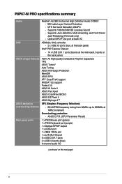
...operating system. 2 x PCI Express 2.0 x16 slot (single at x16 mode, dual at the back panel) (continued on the CPU tpyes. ** Refer to www.asus.com for Intel® CPU support list. at x4 mode, compatible with RAID 0, 1, 5, and 0+1(10) support Marvell® PCIe SATA 6.0 Gb/s controller...only support one DIMM per channel. We recommend a maximum of 3GB system memory if you install a total memory of individual CPUs. P8P67-M PRO specifications summary CPU Chipset Memory Expansion slots Storage LAN IEEE 1394 LGA1155 socket for Intel® Second Generation Core™ i7 / Core...
...operating system. 2 x PCI Express 2.0 x16 slot (single at x16 mode, dual at the back panel) (continued on the CPU tpyes. ** Refer to www.asus.com for Intel® CPU support list. at x4 mode, compatible with RAID 0, 1, 5, and 0+1(10) support Marvell® PCIe SATA 6.0 Gb/s controller...only support one DIMM per channel. We recommend a maximum of 3GB system memory if you install a total memory of individual CPUs. P8P67-M PRO specifications summary CPU Chipset Memory Expansion slots Storage LAN IEEE 1394 LGA1155 socket for Intel® Second Generation Core™ i7 / Core...
User Manual
Page 10
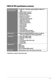
DTS Surround Sensation UltraPC - Supports 192khz/24bit BD Lossless Sound - BD Audio Layer Content Protection - ASUS C.P.R. (CPU Parameter Recall) 1 x PS/2 Mouse port (green) 1 x PS/2 Keyboard port (purple) 1 x Optical S/PDIF output 1 x eSATA port 1 x IEEE 1394a ...Protect 3.0 ASUS AI Suite II ASUS Fan Xpert ASUS CrashFree BIOS 3 ASUS EZ Flash 2 ASUS MyLogo 2™ SFS (Stepless Frequency Selection): - Supports Jack-detection, Multi-streaming, and Front Panel Jack-Retasking (HD mode only) - P8P67-M PRO specifications summary Audio USB ASUS unique features ASUS exclusive ...
DTS Surround Sensation UltraPC - Supports 192khz/24bit BD Lossless Sound - BD Audio Layer Content Protection - ASUS C.P.R. (CPU Parameter Recall) 1 x PS/2 Mouse port (green) 1 x PS/2 Keyboard port (purple) 1 x Optical S/PDIF output 1 x eSATA port 1 x IEEE 1394a ...Protect 3.0 ASUS AI Suite II ASUS Fan Xpert ASUS CrashFree BIOS 3 ASUS EZ Flash 2 ASUS MyLogo 2™ SFS (Stepless Frequency Selection): - Supports Jack-detection, Multi-streaming, and Front Panel Jack-Retasking (HD mode only) - P8P67-M PRO specifications summary Audio USB ASUS unique features ASUS exclusive ...
User Manual
Page 11
P8P67-M PRO specifications summary Internal connectors/ switches/ buttons BIOS features Accessories Support DVD Form factor 4 x USB 2.0/1.1 connectors support additional 8 USB 2.0/1.1 ports 4 x SATA 3.0 Gb/s connectors 3 x SATA 6.0 Gb/s ...BIOS v2.6, Multi-language BIOS 2 x Serial ATA 6.0Gb/s cables 2 x Serial ATA 3.0Gb/s cables 1 x Q-shield 1 x Q-Connector (retail version only) 1 x User Manual 1 x Support DVD Drivers ASUS utilities ASUS Update Anti-virus software (OEM version) uATX form factor: 9.6 in x 9.6 in (24.4 cm x 24.4 cm) * Specifications are subject to change without notice.
P8P67-M PRO specifications summary Internal connectors/ switches/ buttons BIOS features Accessories Support DVD Form factor 4 x USB 2.0/1.1 connectors support additional 8 USB 2.0/1.1 ports 4 x SATA 3.0 Gb/s connectors 3 x SATA 6.0 Gb/s ...BIOS v2.6, Multi-language BIOS 2 x Serial ATA 6.0Gb/s cables 2 x Serial ATA 3.0Gb/s cables 1 x Q-shield 1 x Q-Connector (retail version only) 1 x User Manual 1 x Support DVD Drivers ASUS utilities ASUS Update Anti-virus software (OEM version) uATX form factor: 9.6 in x 9.6 in (24.4 cm x 24.4 cm) * Specifications are subject to change without notice.
User Manual
Page 13
... processors are among the most powerful and energy efficient CPUs in your motherboard package for buying an ASUS® P8P67-M PRO motherboard! Thank you start installing the motherboard, and hardware devices on it another standout in the long...following items. Motherboard Cables Accessories Application DVD Documentation ASUS P8P67-M PRO motherboard 2 x Serial ATA 3.0Gb/s cables 2 x Serial ATA 6.0Gb/s cables 1 x Q-shield 1 x Q-Connector (retail version only) ASUS motherboard support DVD User Manual If any of ASUS quality motherboards! This provides great graphics performance....
... processors are among the most powerful and energy efficient CPUs in your motherboard package for buying an ASUS® P8P67-M PRO motherboard! Thank you start installing the motherboard, and hardware devices on it another standout in the long...following items. Motherboard Cables Accessories Application DVD Documentation ASUS P8P67-M PRO motherboard 2 x Serial ATA 3.0Gb/s cables 2 x Serial ATA 6.0Gb/s cables 1 x Q-shield 1 x Q-Connector (retail version only) ASUS motherboard support DVD User Manual If any of ASUS quality motherboards! This provides great graphics performance....
User Manual
Page 14
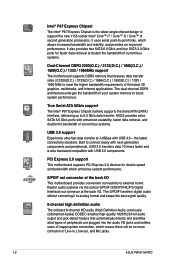
..., faster data retrieval, and double the bandwidth of your system memory to meet the higher bandwidth requirements of Line-in, Line-out, and Mic jacks. 1-2 ASUS P8P67-M PRO Intel® P67 Express Chipset The Intel® P67 Express Chipset is also backward compatible with USB 2.0 components. It also provides two SATA 6.0 Gb/s and...
..., faster data retrieval, and double the bandwidth of your system memory to meet the higher bandwidth requirements of Line-in, Line-out, and Mic jacks. 1-2 ASUS P8P67-M PRO Intel® P67 Express Chipset The Intel® P67 Express Chipset is also backward compatible with USB 2.0 components. It also provides two SATA 6.0 Gb/s and...

User Manual
Page 16
... Fanless Design: stylish heatsink solution The Wing Heatsink features a 0-dB thermal solution that contains the latest BIOS file. 1-4 ASUS P8P67-M PRO The built-in variety of useful profiles offer flexible controls of fan speed to different ambient temperatures caused by power surges from...using the bundled support DVD or USB flash disk that offers users a noiseless PC environment. ASUS MyLogo2™ This feature allows you to use software package. ASUS EPU ASUS EPU is a unique power saving technology that automates overclocking to supervise overclocking, energy management, fan...
... Fanless Design: stylish heatsink solution The Wing Heatsink features a 0-dB thermal solution that contains the latest BIOS file. 1-4 ASUS P8P67-M PRO The built-in variety of useful profiles offer flexible controls of fan speed to different ambient temperatures caused by power surges from...using the bundled support DVD or USB flash disk that offers users a noiseless PC environment. ASUS MyLogo2™ This feature allows you to use software package. ASUS EPU ASUS EPU is a unique power saving technology that automates overclocking to supervise overclocking, energy management, fan...

User Manual
Page 18
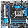
... the image below. 1.5.2 Screw holes Place eight screws into the holes indicated by circles to secure the motherboard to the rear part of the chassis P8P67-M PRO 1-6 ASUS P8P67-M PRO 1.5 Motherboard overview Before you unplug the power cord before installing or removing the motherboard. Place this side towards the rear of the chassis as indicated...
... the image below. 1.5.2 Screw holes Place eight screws into the holes indicated by circles to secure the motherboard to the rear part of the chassis P8P67-M PRO 1-6 ASUS P8P67-M PRO 1.5 Motherboard overview Before you unplug the power cord before installing or removing the motherboard. Place this side towards the rear of the chassis as indicated...
User Manual
Page 21
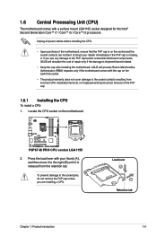
...from incorrect CPU installation/removal, or misplacement/loss/incorrect removal of the PnP cap. 1.6.1 Installing the CPU To install a CPU: 1. P8P67-M PRO P8P67-M PRO CPU socket LGA1155 2. To prevent damage to the socket pins, do not remove the PnP cap unless you see any damage to ... Core™ i7 / Core™ i5 / Core™ i3 processors. Load lever A B Retention tab Chapter 1: Product introduction 1-9 ASUS will process Return Merchandise Authorization (RMA) requests only if the motherboard comes with the cap on the motherboard. Unplug all power cables before installing...
...from incorrect CPU installation/removal, or misplacement/loss/incorrect removal of the PnP cap. 1.6.1 Installing the CPU To install a CPU: 1. P8P67-M PRO P8P67-M PRO CPU socket LGA1155 2. To prevent damage to the socket pins, do not remove the PnP cap unless you see any damage to ... Core™ i7 / Core™ i5 / Core™ i3 processors. Load lever A B Retention tab Chapter 1: Product introduction 1-9 ASUS will process Return Merchandise Authorization (RMA) requests only if the motherboard comes with the cap on the motherboard. Unplug all power cables before installing...
User Manual
Page 22
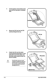
... the load lever in only one correct orientation. DO NOT force the CPU into the CPU notches. Gold triangle mark Alignment keys CPU notches 1-10 ASUS P8P67-M PRO 3. Position the CPU over the socket, ensuring that the gold triangle is completely lifted.
... the load lever in only one correct orientation. DO NOT force the CPU into the CPU notches. Gold triangle mark Alignment keys CPU notches 1-10 ASUS P8P67-M PRO 3. Position the CPU over the socket, ensuring that the gold triangle is completely lifted.
User Manual
Page 24
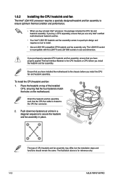
... and fan: A 1. The illustration above is incompatible with the LGA775 and LGA1366 sockets in size and dimension. The LGA1155 socket is for reference only. 1-12 ASUS P8P67-M PRO 1.6.2 Installing the CPU heatsink and fan The Intel® LGA1155 processor requires a specially designed heatsink and fan assembly to ensure optimum thermal condition and performance...
... and fan: A 1. The illustration above is incompatible with the LGA775 and LGA1366 sockets in size and dimension. The LGA1155 socket is for reference only. 1-12 ASUS P8P67-M PRO 1.6.2 Installing the CPU heatsink and fan The Intel® LGA1155 processor requires a specially designed heatsink and fan assembly to ensure optimum thermal condition and performance...
User Manual
Page 25
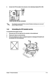
... up two fasteners at a time in a diagonal sequence to the connector on the motherboard. 2. CPU_FAN CPU FAN PWM CPU FAN IN CPU FAN PWR GND P8P67-M PRO P8P67-M PRO CPU fan connector Do not forget to plug this connector. 1.6.3 Uninstalling the CPU heatsink and fan To uninstall the CPU heatsink and fan: 1. Disconnect the...
... up two fasteners at a time in a diagonal sequence to the connector on the motherboard. 2. CPU_FAN CPU FAN PWM CPU FAN IN CPU FAN PWR GND P8P67-M PRO P8P67-M PRO CPU fan connector Do not forget to plug this connector. 1.6.3 Uninstalling the CPU heatsink and fan To uninstall the CPU heatsink and fan: 1. Disconnect the...
User Manual
Page 26
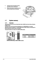
... less power consumption. 4. The figure illustrates the location of the DDR3 DIMM sockets: DIMM_A1 DIMM_A2 DIMM_B1 DIMM_B2 P8P67-M PRO Channel Channel A Channel B Sockets DIMM_A1 and DIMM_A2 DIMM_B1 and DIMM_B2 P8P67-M PRO 240-pin DDR3 DIMM sockets 1-14 ASUS P8P67-M PRO Carefully remove the heatsink and fan assembly from the motherboard. 5. DDR3 modules are developed for better performance...
... less power consumption. 4. The figure illustrates the location of the DDR3 DIMM sockets: DIMM_A1 DIMM_A2 DIMM_B1 DIMM_B2 P8P67-M PRO Channel Channel A Channel B Sockets DIMM_A1 and DIMM_A2 DIMM_B1 and DIMM_B2 P8P67-M PRO 240-pin DDR3 DIMM sockets 1-14 ASUS P8P67-M PRO Carefully remove the heatsink and fan assembly from the motherboard. 5. DDR3 modules are developed for better performance...
User Manual
Page 32
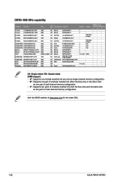
Size SS/ DS Chip Brand Chip NO. Visit the ASUS website at www.asus.com for the latest QVL. 1-20 ASUS P8P67-M PRO Crucial Crucial CT12864BA1067.8FF 1GB CT25664BA1067.16FF 2GB SS Micron DS Micron 9GF22D9KPT 9HF22D9KPT ELPIDA EBJ10UE8EDF0-AE-F 1GB SS ELPIDA J1108EDSE-DJ-F ELPIDA EBJ11UD8BAFA-AE-E ...
Size SS/ DS Chip Brand Chip NO. Visit the ASUS website at www.asus.com for the latest QVL. 1-20 ASUS P8P67-M PRO Crucial Crucial CT12864BA1067.8FF 1GB CT25664BA1067.16FF 2GB SS Micron DS Micron 9GF22D9KPT 9HF22D9KPT ELPIDA EBJ10UE8EDF0-AE-F 1GB SS ELPIDA J1108EDSE-DJ-F ELPIDA EBJ11UD8BAFA-AE-E ...
User Manual
Page 34
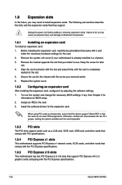
... and make the necessary hardware settings for later use . Before installing the expansion card, read the documentation that came with the PCI Express specifications. 1-22 ASUS P8P67-M PRO Assign an IRQ to install expansion cards. Otherwise, conflicts will arise between the two PCI groups, making the system unstable and the card inoperable. 1.8.3 PCI...
... and make the necessary hardware settings for later use . Before installing the expansion card, read the documentation that came with the PCI Express specifications. 1-22 ASUS P8P67-M PRO Assign an IRQ to install expansion cards. Otherwise, conflicts will arise between the two PCI groups, making the system unstable and the card inoperable. 1.8.3 PCI...
User Manual
Page 36
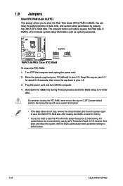
...steps above do not need to clear the RTC when the system hangs due to overclocking. For system failure due to default values. 1-24 ASUS P8P67-M PRO Turn OFF the computer and unplug the power cord. 2. Shut down the key during the boot process and enter BIOS setup to re-... settings to overclocking, use the CPU Parameter Recall (C.P.R.) feature. The onboard button cell battery powers the RAM data in CMOS. P8P67-M PRO CLRTC 12 23 Normal (Default) Clear RTC P8P67-M PRO Clear RTC RAM To erase the RTC RAM: 1. 1.9 Jumpers Clear RTC RAM (3-pin CLRTC) This jumper allows you to ...
...steps above do not need to clear the RTC when the system hangs due to overclocking. For system failure due to default values. 1-24 ASUS P8P67-M PRO Turn OFF the computer and unplug the power cord. 2. Shut down the key during the boot process and enter BIOS setup to re-... settings to overclocking, use the CPU Parameter Recall (C.P.R.) feature. The onboard button cell battery powers the RAM data in CMOS. P8P67-M PRO CLRTC 12 23 Normal (Default) Clear RTC P8P67-M PRO Clear RTC RAM To erase the RTC RAM: 1. 1.9 Jumpers Clear RTC RAM (3-pin CLRTC) This jumper allows you to ...
User Manual
Page 38
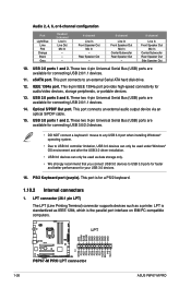
.../2 Keyboard port (purple). LPT AFD ERR# INIT# SLIN# GND GND GND GND GND GND GND GND 1-26 P8P67-M PRO P8P67-M PRO LPT connector PIN 1 STB# PD0 PD1 PD2 PD3 PD4 PD5 PD6 PD7 ACK# BUSY PE SLCT ASUS P8P67-M PRO These two 4-pin Universal Serial Bus (USB) ports are available for a PS/2 keyboard. 1.10.2 Internal connectors 1. LPT...
.../2 Keyboard port (purple). LPT AFD ERR# INIT# SLIN# GND GND GND GND GND GND GND GND 1-26 P8P67-M PRO P8P67-M PRO LPT connector PIN 1 STB# PD0 PD1 PD2 PD3 PD4 PD5 PD6 PD7 ACK# BUSY PE SLCT ASUS P8P67-M PRO These two 4-pin Universal Serial Bus (USB) ports are available for a PS/2 keyboard. 1.10.2 Internal connectors 1. LPT...
User Manual
Page 39
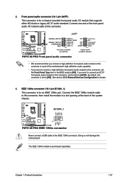
... connector is purchased separately. See section 2.5.6 Onboard Devices Configuration for a chassis-mounted front panel audio I /O module cable to [HD]. AAFP P8P67-M PRO SENSE2_RETUR SENSE1_RETUR PRESENCE# GND PORT2 L NC SENSE_SEND PORT2 R NC PORT1 R NC PORT1 L AGND PIN 1 Line out_L NC Line out_R MICPWR ...MIC2 PIN 1 HD-audio-compliant pin definition Legacy AC'97 compliant definition P8P67-M PRO Front panel audio connector • We recommend that supports either HD Audio or legacy AC`97 audio standard. Connect the IEEE ...
... connector is purchased separately. See section 2.5.6 Onboard Devices Configuration for a chassis-mounted front panel audio I /O module cable to [HD]. AAFP P8P67-M PRO SENSE2_RETUR SENSE1_RETUR PRESENCE# GND PORT2 L NC SENSE_SEND PORT2 R NC PORT1 R NC PORT1 L AGND PIN 1 Line out_L NC Line out_R MICPWR ...MIC2 PIN 1 HD-audio-compliant pin definition Legacy AC'97 compliant definition P8P67-M PRO Front panel audio connector • We recommend that supports either HD Audio or legacy AC`97 audio standard. Connect the IEEE ...
User Manual
Page 40
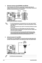
...connector is for details. 5. Find the proper orientation and push down firmly until the connectors completely fit. COM1 PIN 1 P8P67-M PRO P8P67-M PRO Serial port (COM1) connector The COM module is inadequate. • If you are designed to the Recommended Power Supply... fit these connectors in only one orientation. EATX12V EATXPWR +12V DC +12V DC +12V DC +12V DC P8P67-M PRO GND GND GND GND +3 Volts +12 Volts +12 Volts +5V Standby Power OK PIN 1 GND +5 Volts GND +5 Volts .... Otherwise, the system will not boot up if the power is purchased separately. 1-28 ASUS P8P67-M PRO
...connector is for details. 5. Find the proper orientation and push down firmly until the connectors completely fit. COM1 PIN 1 P8P67-M PRO P8P67-M PRO Serial port (COM1) connector The COM module is inadequate. • If you are designed to the Recommended Power Supply... fit these connectors in only one orientation. EATX12V EATXPWR +12V DC +12V DC +12V DC +12V DC P8P67-M PRO GND GND GND GND +3 Volts +12 Volts +12 Volts +5V Standby Power OK PIN 1 GND +5 Volts GND +5 Volts .... Otherwise, the system will not boot up if the power is purchased separately. 1-28 ASUS P8P67-M PRO


