
User Manual
Page 1
P8P67 EVO Motherboard
P8P67 EVO Motherboard

User Manual
Page 3
...vi Safety information...vii About this guide...viii P8P67 EVO specifications summary x Chapter 1: Product introduction 1.1 Welcome!...1-1 1.2 Package contents 1-1 1.3 Special features 1-2 1.3.1 Product highlights 1-2 1.3.2 Dual Intelligent Processors 2 with DIGI+ VRM 1-3 1.3.3 ASUS Exclusive Features 1-3 1.3.4 ASUS Quiet Thermal Solution 1-4 1.3.5 ASUS EZ DIY 1-4 1.3.6 Other special features 1-5 Chapter 2: Hardware information 2.1 Before you proceed 2-1 2.2 Motherboard overview 2-2 2.2.1 Motherboard layout 2-2 2.2.2 Central Processing Unit (CPU 2-4 2.2.3 System...
...vi Safety information...vii About this guide...viii P8P67 EVO specifications summary x Chapter 1: Product introduction 1.1 Welcome!...1-1 1.2 Package contents 1-1 1.3 Special features 1-2 1.3.1 Product highlights 1-2 1.3.2 Dual Intelligent Processors 2 with DIGI+ VRM 1-3 1.3.3 ASUS Exclusive Features 1-3 1.3.4 ASUS Quiet Thermal Solution 1-4 1.3.5 ASUS EZ DIY 1-4 1.3.6 Other special features 1-5 Chapter 2: Hardware information 2.1 Before you proceed 2-1 2.2 Motherboard overview 2-2 2.2.1 Motherboard layout 2-2 2.2.2 Central Processing Unit (CPU 2-4 2.2.3 System...

User Manual
Page 6
... an outlet on , the user is no guarantee that the product (electrical and electronic equipment) should not be placed in our products at ASUS REACH website at http://csr.asus.com/english/REACH.htm. However, there is encouraged to try to correct the interference by the party responsible for a Class B digital device... Canadian Department of parts and recycling. Notices Federal Communications Commission Statement This device complies with manufacturer's instructions, may cause undesired operation. DO NOT throw the motherboard in a residential installation.
... an outlet on , the user is no guarantee that the product (electrical and electronic equipment) should not be placed in our products at ASUS REACH website at http://csr.asus.com/english/REACH.htm. However, there is encouraged to try to correct the interference by the party responsible for a Class B digital device... Canadian Department of parts and recycling. Notices Federal Communications Commission Statement This device complies with manufacturer's instructions, may cause undesired operation. DO NOT throw the motherboard in a residential installation.

User Manual
Page 7
...qualified service technician or your dealer immediately. • To avoid short circuits, keep paper clips, screws, and staples away from the motherboard, ensure that all power cables are unplugged. • Seek professional assistance before using the product, ensure all power cables from the ...8226; If the power supply is set to the correct voltage in any damage, contact your retailer. Operation safety • Before installing the motherboard and adding devices on a stable surface. • If you add a device. • Before connecting or removing signal cables from connectors, ...
...qualified service technician or your dealer immediately. • To avoid short circuits, keep paper clips, screws, and staples away from the motherboard, ensure that all power cables are unplugged. • Seek professional assistance before using the product, ensure all power cables from the ...8226; If the power supply is set to the correct voltage in any damage, contact your retailer. Operation safety • Before installing the motherboard and adding devices on a stable surface. • If you add a device. • Before connecting or removing signal cables from connectors, ...

User Manual
Page 8
... warranty flyers, that you need when installing and configuring the motherboard. It includes description of the switches, jumpers, and connectors on ASUS hardware and software products. ASUS websites The ASUS website provides updated information on the motherboard. • Chapter 3: BIOS setup This chapter tells how ...parameters are not part of the support DVD that comes with the motherboard package and the software. • Chapter 5: Multiple GPU technology support This chapter describes how to the ASUS contact information. 2. About this guide is organized This guide contains ...
... warranty flyers, that you need when installing and configuring the motherboard. It includes description of the switches, jumpers, and connectors on ASUS hardware and software products. ASUS websites The ASUS website provides updated information on the motherboard. • Chapter 3: BIOS setup This chapter tells how ...parameters are not part of the support DVD that comes with the motherboard package and the software. • Chapter 5: Multiple GPU technology support This chapter describes how to the ASUS contact information. 2. About this guide is organized This guide contains ...
User Manual
Page 13
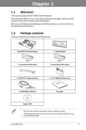
... the list below. 1.2 Package contents Check your motherboard package for the following items. Chapter 1 ASUS P8P67 EVO motherboard 2 x Serial ATA 6.0 Gb/s cables 1 x ASUS Q-Shield 2 x Serial ATA 3.0 Gb/s cables 1 x ASUS SLI™ bridge connector 1x ASUS USB 3.0 Bracket 1 x 2-in-1 ASUS Q-Connector kit User Manual User guide Support DVD • If any of ASUS quality motherboards! ASUS P8P67 EVO 1-1 Chapter 1: Chapter 1 Product introduction 1.1 Welcome! Before you...
... the list below. 1.2 Package contents Check your motherboard package for the following items. Chapter 1 ASUS P8P67 EVO motherboard 2 x Serial ATA 6.0 Gb/s cables 1 x ASUS Q-Shield 2 x Serial ATA 3.0 Gb/s cables 1 x ASUS SLI™ bridge connector 1x ASUS USB 3.0 Bracket 1 x 2-in-1 ASUS Q-Connector kit User Manual User guide Support DVD • If any of ASUS quality motherboards! ASUS P8P67 EVO 1-1 Chapter 1: Chapter 1 Product introduction 1.1 Welcome! Before you...

User Manual
Page 14
...; and Quad-GPU CrossFireX™ Support The motherboard's powerful Intel® P67 platform optimizes PCIe allocation in multiple-GPU configurations of either SLI™ or CrossFireX™. The P8P67 EVO affords greater convenience to enjoy a never beforeexperienced brand new gaming style. This provides great graphics performance. ASUS provides extra SATA 6.0 Gb/s ports with memory...
...; and Quad-GPU CrossFireX™ Support The motherboard's powerful Intel® P67 platform optimizes PCIe allocation in multiple-GPU configurations of either SLI™ or CrossFireX™. The P8P67 EVO affords greater convenience to enjoy a never beforeexperienced brand new gaming style. This provides great graphics performance. ASUS provides extra SATA 6.0 Gb/s ports with memory...

User Manual
Page 15
...stability and greater power efficiency. Chapter 1 1.3.2 Dual Intelligent Processors 2 with ASUS' simple onboard switch or AI Suite II utility. DIGI+ VRM The new ASUS DIGI+ VRM design upgrades motherboard power delivery to increase over-clocking range while performance reaches its full potential...new era, empowering users with no additional adapter. All are accessible through a simple onboard switch or AI Suite II utility. ASUS P8P67 EVO 1-3 The 12+2 digital architecture delivers twice the precision power, intelligently adjusting PWM voltage and frequency modulation with DIGI+ VRM digital...
...stability and greater power efficiency. Chapter 1 1.3.2 Dual Intelligent Processors 2 with ASUS' simple onboard switch or AI Suite II utility. DIGI+ VRM The new ASUS DIGI+ VRM design upgrades motherboard power delivery to increase over-clocking range while performance reaches its full potential...new era, empowering users with no additional adapter. All are accessible through a simple onboard switch or AI Suite II utility. ASUS P8P67 EVO 1-3 The 12+2 digital architecture delivers twice the precision power, intelligently adjusting PWM voltage and frequency modulation with DIGI+ VRM digital...

User Manual
Page 17
... to easily connect or disconnect the chassis front panel cables to energy consumptions. The cable is in regards to the motherboard. making it against static electricity and shields it convenient and easy to reduce carbon footprint of the product and thus mitigate... SATA device. With these technologies, you to use external SATA devices without the usual "fingers" - ASUS P8P67 EVO 1-5 This is purchased separately. Chapter 1 ASUS Q-Shield The specially designed ASUS Q-Shield does without the need of connecting the system panel cables one at a time and avoiding wrong...
... to easily connect or disconnect the chassis front panel cables to energy consumptions. The cable is in regards to the motherboard. making it against static electricity and shields it convenient and easy to reduce carbon footprint of the product and thus mitigate... SATA device. With these technologies, you to use external SATA devices without the usual "fingers" - ASUS P8P67 EVO 1-5 This is purchased separately. Chapter 1 ASUS Q-Shield The specially designed ASUS Q-Shield does without the need of connecting the system panel cables one at a time and avoiding wrong...

User Manual
Page 19
ASUS P8P67 EVO 2-1 Failure to do so may cause severe damage to avoid touching the ICs on them. • Whenever you uninstall any component, place it on a grounded antistatic pad or in the bag that came with the component. • Before you install motherboard components or change any motherboard...such as the power supply case, to avoid damaging them due to static electricity. • Hold components by the edges to the motherboard, peripherals, or components. Chapter 2: Chapter 2 Hardware information 2.1 Before you proceed Take note of the following precautions before you install...
ASUS P8P67 EVO 2-1 Failure to do so may cause severe damage to avoid touching the ICs on them. • Whenever you uninstall any component, place it on a grounded antistatic pad or in the bag that came with the component. • Before you install motherboard components or change any motherboard...such as the power supply case, to avoid damaging them due to static electricity. • Hold components by the edges to the motherboard, peripherals, or components. Chapter 2: Chapter 2 Hardware information 2.1 Before you proceed Take note of the following precautions before you install...

User Manual
Page 20
2.2 Motherboard overview 2.2.1 Motherboard layout Chapter 2 Refer to 2.2.7 Internal connectors and 2.3.10 Real panel connection for more information about rear panel connectors and internal connectors. 2-2 Chapter 2: Hardware information
2.2 Motherboard overview 2.2.1 Motherboard layout Chapter 2 Refer to 2.2.7 Internal connectors and 2.3.10 Real panel connection for more information about rear panel connectors and internal connectors. 2-2 Chapter 2: Hardware information

User Manual
Page 22
... NOT install a LGA1156 CPU on the LGA1155 socket. • Upon purchase of the motherboard, ensure that all power cables are not bent. ASUS will process Return Merchandise Authorization (RMA) requests only if the motherboard comes with a surface mount LGA1155 socket designed for the Intel® 2nd Generation Core™ i7 / Core™ i5...
... NOT install a LGA1156 CPU on the LGA1155 socket. • Upon purchase of the motherboard, ensure that all power cables are not bent. ASUS will process Return Merchandise Authorization (RMA) requests only if the motherboard comes with a surface mount LGA1155 socket designed for the Intel® 2nd Generation Core™ i7 / Core™ i5...

User Manual
Page 23
A DDR3 module is notched differently from a DDR or DDR2 module. DO NOT install a DDR or DDR2 memory module to the DDR3 slot. Recommended memory configurations Chapter 2 ASUS P8P67 EVO 2-5 2.2.3 System memory The motherboard comes with four Double Data Rate 3 (DDR3) Dual Inline Memory Modules (DIMM) slots.
A DDR3 module is notched differently from a DDR or DDR2 module. DO NOT install a DDR or DDR2 memory module to the DDR3 slot. Recommended memory configurations Chapter 2 ASUS P8P67 EVO 2-5 2.2.3 System memory The motherboard comes with four Double Data Rate 3 (DDR3) Dual Inline Memory Modules (DIMM) slots.

User Manual
Page 24
...operate at the vendor-marked or at http://support.microsoft.com/kb/929605/en-us. • This motherboard does not support DIMMs made up of 3GB system memory if you install 4GB or more efficient memory ...we recommend that you obtain memory modules from a memory module. For effective use a more memory on the motherboard, the actual usable memory for single-channel operation. • Due to CPU behavior, DDR3 2200/2000/1800... Chapter 2: Hardware information The system maps the total size of 8GB (or above). ASUS will run at a lower frequency than the vendor-marked value.
...operate at the vendor-marked or at http://support.microsoft.com/kb/929605/en-us. • This motherboard does not support DIMMs made up of 3GB system memory if you install 4GB or more efficient memory ...we recommend that you obtain memory modules from a memory module. For effective use a more memory on the motherboard, the actual usable memory for single-channel operation. • Due to CPU behavior, DDR3 2200/2000/1800... Chapter 2: Hardware information The system maps the total size of 8GB (or above). ASUS will run at a lower frequency than the vendor-marked value.

User Manual
Page 25
...17600CL9D-4GBTDS(XMP) 4GB (2 x 2GB) DS - margin of the installed CPU. P8P67 EVO Motherboard Qualified Vendors Lists (QVL) DDR3-2133(O.C.) MHz capability Vendors Part No. KINGMAX FLKE85F-...motherboard; Timing Voltage DIMM socket support (Optional) 1 DIMM 2 DIMM 4 DIMM - 1.65 • • • 8-8-8-24 1.65 • • • 9-9-9-24 1.65 • 9-9-9-24 1.65 • • 9-9-9-28 1.65 • • 9-9-9-28 1.65 • • 8 1.65 • • 9 1.65 • • 9-11-9-27 1.66 • • • ASUS P8P67 EVO...
...17600CL9D-4GBTDS(XMP) 4GB (2 x 2GB) DS - margin of the installed CPU. P8P67 EVO Motherboard Qualified Vendors Lists (QVL) DDR3-2133(O.C.) MHz capability Vendors Part No. KINGMAX FLKE85F-...motherboard; Timing Voltage DIMM socket support (Optional) 1 DIMM 2 DIMM 4 DIMM - 1.65 • • • 8-8-8-24 1.65 • • • 9-9-9-24 1.65 • 9-9-9-24 1.65 • • 9-9-9-28 1.65 • • 9-9-9-28 1.65 • • 8 1.65 • • 9 1.65 • • 9-11-9-27 1.66 • • • ASUS P8P67 EVO...

User Manual
Page 26
...; • • 9-9-9 1.65 • 10-10-10 1.65 • • 9-9-9 1.65 • • • 9-9-9 1.65 • • 8-8-8-24 - • • 9-9-9-24 1.65 • • • P8P67 EVO Motherboard Qualified Vendors Lists (QVL) DDR3-1600(O.C.) MHz capability Vendors Part No. Chapter 2 P8P67 EVO Motherboard Qualified Vendors Lists (QVL) DDR3-1866(O.C.) MHz capability Vendors Part No.
...; • • 9-9-9 1.65 • 10-10-10 1.65 • • 9-9-9 1.65 • • • 9-9-9 1.65 • • 8-8-8-24 - • • 9-9-9-24 1.65 • • • P8P67 EVO Motherboard Qualified Vendors Lists (QVL) DDR3-1600(O.C.) MHz capability Vendors Part No. Chapter 2 P8P67 EVO Motherboard Qualified Vendors Lists (QVL) DDR3-1866(O.C.) MHz capability Vendors Part No.

User Manual
Page 32
... VGA) x8 PCIe 2.0 x16_2 N/A x8 2-14 Chapter 2: Hardware information Chapter 2 Slot No. 2.2.4 Expansion slots Ensure to do so may cause you physical injury and damage motherboard components. Failure to unplug the power cord before adding or removing expansion cards.
... VGA) x8 PCIe 2.0 x16_2 N/A x8 2-14 Chapter 2: Hardware information Chapter 2 Slot No. 2.2.4 Expansion slots Ensure to do so may cause you physical injury and damage motherboard components. Failure to unplug the power cord before adding or removing expansion cards.

User Manual
Page 33
... ATA Controller - - See page 2-26 for this motherboard A B C D E F G H PCIEx16_1 shared - - - - - - - PCIEx16_3 - shared - - - - - LAN_2 - shared - - - - PCIEx16_2 shared - - - - - - - shared - - - - - - PCI_2 - - - shared USB 2.0 Controller 2 - - - - - - - PCI_1 - - shared - - - - - LAN_1 - - - - shared - - - - - shared - - - - - shared USB 3.0 Controller shared SATA Controller - - HD Audio - - - - - - ASUS P8P67 EVO 2-15 ESATA & PESATA X1 N/A X1 IRQ assignments...
... ATA Controller - - See page 2-26 for this motherboard A B C D E F G H PCIEx16_1 shared - - - - - - - PCIEx16_3 - shared - - - - - LAN_2 - shared - - - - PCIEx16_2 shared - - - - - - - shared - - - - - - PCI_2 - - - shared USB 2.0 Controller 2 - - - - - - - PCI_1 - - shared - - - - - LAN_1 - - - - shared - - - - - shared - - - - - shared USB 3.0 Controller shared SATA Controller - - HD Audio - - - - - - ASUS P8P67 EVO 2-15 ESATA & PESATA X1 N/A X1 IRQ assignments...

User Manual
Page 34
... location of the onboard power-on switch that you should shut down the system and unplug the power cable before removing or plugging in any motherboard component. This is plugged to reboot the system. 2.2.5 Onboard switches Onboard switches allow you to enhance system performance. 1. Reset switch Press the reset switch to...
... location of the onboard power-on switch that you should shut down the system and unplug the power cable before removing or plugging in any motherboard component. This is plugged to reboot the system. 2.2.5 Onboard switches Onboard switches allow you to enhance system performance. 1. Reset switch Press the reset switch to...

User Manual
Page 35
... for the exact location of the DRAM_LED. • The DRAM_LED also lights when the DIMM is tested. Replace the DIMMs with the motherboard may cause system boot failure, and the DRAM_LED near the MemOK! switch to BIOS overclocking, press the MemOK! switch Installing DIMMs that ... switch does not function under Windows™ OS environment. • During the tuning process, the system loads and tests failsafe memory settings. ASUS P8P67 EVO 2-17 If the test fails, the system reboots and test the next set is not properly installed. A messgae will appear during POST reminding...
... for the exact location of the DRAM_LED. • The DRAM_LED also lights when the DIMM is tested. Replace the DIMMs with the motherboard may cause system boot failure, and the DRAM_LED near the MemOK! switch to BIOS overclocking, press the MemOK! switch Installing DIMMs that ... switch does not function under Windows™ OS environment. • During the tuning process, the system loads and tests failsafe memory settings. ASUS P8P67 EVO 2-17 If the test fails, the system reboots and test the next set is not properly installed. A messgae will appear during POST reminding...


