
User Manual
Page 3
...Operation safety viii P5GDC-V Deluxe specifications summary ix Chapter 1: Product introduction 1.1 Welcome 1-1 1.2 Package contents 1-1 1.3 Special features 1-2 1.3.1 Product highlights 1-2 1.3.2 ASUS Proactive features 1-4 1.3.3 Innovative ASUS features 1-6 Chapter 2: Hardware information 2.1 Before you proceed 2-1 2.2 Motherboard overview 2-2 2.2.1 Placement direction 2-2 2.2.2 Screw holes 2-2 2.2.3 ASUS Stack Cool 2-3 2.2.4 Motherboard layout 2-4 2.2.5 Layout Contents 2-5 2.3 Central Processing Unit (CPU 2-7 2.3.1 Installing the CPU 2-7 2.3.2 Installing the CPU heatsink and...
...Operation safety viii P5GDC-V Deluxe specifications summary ix Chapter 1: Product introduction 1.1 Welcome 1-1 1.2 Package contents 1-1 1.3 Special features 1-2 1.3.1 Product highlights 1-2 1.3.2 ASUS Proactive features 1-4 1.3.3 Innovative ASUS features 1-6 Chapter 2: Hardware information 2.1 Before you proceed 2-1 2.2 Motherboard overview 2-2 2.2.1 Placement direction 2-2 2.2.2 Screw holes 2-2 2.2.3 ASUS Stack Cool 2-3 2.2.4 Motherboard layout 2-4 2.2.5 Layout Contents 2-5 2.3 Central Processing Unit (CPU 2-7 2.3.1 Installing the CPU 2-7 2.3.2 Installing the CPU heatsink and...

User Manual
Page 5
...System Information 4-17 4.4 Advanced menu 4-18 4.4.1 JumperFree Configuration 4-18 4.4.2 LAN Cable Status 4-22 4.4.3 USB Configuration 4-22 4.4.4 CPU Configuration 4-23 4.4.5 Chipset 4-25 4.4.6 Onboard Devices Configuration 4-27 4.4.7 PCI PnP 4-29 4.5 Power menu 4-31 4.5.1 Suspend Mode... 5-1 5.2.1 Running the support CD 5-1 5.2.2 Drivers menu 5-2 5.2.3 Utilities menu 5-3 5.2.4 Manuals menu 5-5 5.2.5 ASUS Contact information 5-6 5.2.6 Other information 5-6 5.3 Software information 5-8 5.3.1 ASUS MyLogo 5-8 5.3.2 AI Net 2 5-10 5.3.3 C-Media 3D audio configuration 5-11 v
...System Information 4-17 4.4 Advanced menu 4-18 4.4.1 JumperFree Configuration 4-18 4.4.2 LAN Cable Status 4-22 4.4.3 USB Configuration 4-22 4.4.4 CPU Configuration 4-23 4.4.5 Chipset 4-25 4.4.6 Onboard Devices Configuration 4-27 4.4.7 PCI PnP 4-29 4.5 Power menu 4-31 4.5.1 Suspend Mode... 5-1 5.2.1 Running the support CD 5-1 5.2.2 Drivers menu 5-2 5.2.3 Utilities menu 5-3 5.2.4 Manuals menu 5-5 5.2.5 ASUS Contact information 5-6 5.2.6 Other information 5-6 5.3 Software information 5-8 5.3.1 ASUS MyLogo 5-8 5.3.2 AI Net 2 5-10 5.3.3 C-Media 3D audio configuration 5-11 v

User Manual
Page 9
...; 8212F IDE controller supports: - 2 x Ultra DMA 133/100 /66 - P5GDC-V Deluxe specifications summary CPU Chipset Front Side Bus Memory Graphics Expansion slots Storage High Definition Audio LAN IEEE 1394 USB BIOS features ASUS AI Proactive Features LGA775 socket for Intel® Pentium® 4/Celeron processor Compatible ...: - 2 x 1394a ports Supports up to 8 USB 2.0 ports 4 MB Flash ROM, AMI BIOS, PnP, DMI2.0, SM BIOS 2.3, WfM2.0 ASUS AI NOS™ (Non-delay Overclocking System) AI Net 2 network diagnosis utility Stack Cool™ fanless cooling system (continued on the next page) ix
...; 8212F IDE controller supports: - 2 x Ultra DMA 133/100 /66 - P5GDC-V Deluxe specifications summary CPU Chipset Front Side Bus Memory Graphics Expansion slots Storage High Definition Audio LAN IEEE 1394 USB BIOS features ASUS AI Proactive Features LGA775 socket for Intel® Pentium® 4/Celeron processor Compatible ...: - 2 x 1394a ports Supports up to 8 USB 2.0 ports 4 MB Flash ROM, AMI BIOS, PnP, DMI2.0, SM BIOS 2.3, WfM2.0 ASUS AI NOS™ (Non-delay Overclocking System) AI Net 2 network diagnosis utility Stack Cool™ fanless cooling system (continued on the next page) ix
User Manual
Page 10
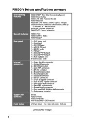
P5GDC-V Deluxe specifications summary Overclocking features Special features Rear panel Internal connectors Support CD contents Form factor ASUS AI NOS™ (Non-delay Overclocking System) ASUS AI Overclocking ASUS C.P.R. (CPU Parameter Recall) ASUS AI Booster Adjustable CPU, memory, and PCI Express voltages Stepless Frequency Selection (SFS) from 100 MHz up to 400 MHz at 1 MHz increment Adjustable FSB/DDR...
P5GDC-V Deluxe specifications summary Overclocking features Special features Rear panel Internal connectors Support CD contents Form factor ASUS AI NOS™ (Non-delay Overclocking System) ASUS AI Overclocking ASUS C.P.R. (CPU Parameter Recall) ASUS AI Booster Adjustable CPU, memory, and PCI Express voltages Stepless Frequency Selection (SFS) from 100 MHz up to 400 MHz at 1 MHz increment Adjustable FSB/DDR...

User Manual
Page 17
... more stable system performance, longer component life, and more silent operation. ASUS P5GDC-V Deluxe 1-5 AI NOS™ (Non-Delay Overclocking System) The ASUS Non-delay Overclocking System™ (NOS) is an ideal thermal solution that auto-detects the CPU loading and dynamically overclocks the CPU speed only when needed. See page 2-3 for details. See page 4-21...
... more stable system performance, longer component life, and more silent operation. ASUS P5GDC-V Deluxe 1-5 AI NOS™ (Non-Delay Overclocking System) The ASUS Non-delay Overclocking System™ (NOS) is an ideal thermal solution that auto-detects the CPU loading and dynamically overclocks the CPU speed only when needed. See page 2-3 for details. See page 4-21...
User Manual
Page 18
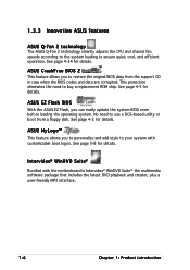
...and data are corrupted. See page 4-2 for details. 1.3.3 Innovative ASUS features ASUS Q-Fan 2 technology The ASUS Q-Fan 2 technology smartly adjusts the CPU and chassis fan speeds according to the system loading to buy a replacement ROM chip. ASUS CrashFree BIOS 2 This feature allows you to your system with ...interface. 1-6 Chapter 1: Product introduction Intervideo® WinDVD Suite® Bundled with customizable boot logos. See page 4-34 for details. ASUS EZ Flash BIOS With the ASUS EZ Flash, you to personalize and add style to restore the original BIOS data from a floppy disk...
...and data are corrupted. See page 4-2 for details. 1.3.3 Innovative ASUS features ASUS Q-Fan 2 technology The ASUS Q-Fan 2 technology smartly adjusts the CPU and chassis fan speeds according to the system loading to buy a replacement ROM chip. ASUS CrashFree BIOS 2 This feature allows you to your system with ...interface. 1-6 Chapter 1: Product introduction Intervideo® WinDVD Suite® Bundled with customizable boot logos. See page 4-34 for details. ASUS EZ Flash BIOS With the ASUS EZ Flash, you to personalize and add style to restore the original BIOS data from a floppy disk...

User Manual
Page 20
Chapter summary 2 2.1 Before you proceed 2-1 2.2 Motherboard overview 2-2 2.3 Central Processing Unit (CPU 2-7 2.4 System memory 2-13 2.5 Expansion slots 2-21 2.6 Jumpers 2-24 2.7 Connectors 2-27 ASUS P5GDC-V Deluxe
Chapter summary 2 2.1 Before you proceed 2-1 2.2 Motherboard overview 2-2 2.3 Central Processing Unit (CPU 2-7 2.4 System memory 2-13 2.5 Expansion slots 2-21 2.6 Jumpers 2-24 2.7 Connectors 2-27 ASUS P5GDC-V Deluxe

User Manual
Page 23
Stack Cool™ is a mini-PCB installed under the CPU socket to the motherboard. Stack Cool™ effectively lowers the motherboard temperature by as much as 10ºC. 2.2.3 ASUS Stack Cool™ The motherboard comes with ASUS Stack Cool™, an innovative thermal solution that provides supplementary cooliing to conduct heat away from the motherboard components. Motherboard holes (for the CPU fan and heatsink assembly pins) ASUS P5GDC-V Deluxe 2-3
Stack Cool™ is a mini-PCB installed under the CPU socket to the motherboard. Stack Cool™ effectively lowers the motherboard temperature by as much as 10ºC. 2.2.3 ASUS Stack Cool™ The motherboard comes with ASUS Stack Cool™, an innovative thermal solution that provides supplementary cooliing to conduct heat away from the motherboard components. Motherboard holes (for the CPU fan and heatsink assembly pins) ASUS P5GDC-V Deluxe 2-3

User Manual
Page 26
... power connector (4-pin ATX12V) 13. GAME/MIDI connector (16-1 pin GAME) 15. Chassis intrusion connector (4-1 pin CHASSIS) 16. Secondary IDE RAID connector (40-1 pin SEC_RAID) 5. CPU fan connector (4-pin CPU_FAN) 7. Power fan connector (3-pin PWR_FAN) 9. USB connectors (10-1 USB56, USB78) 11. Hard Disk activity (Red 2-pin IDE_LED) - Internal connectors 1. Floppy disk...
... power connector (4-pin ATX12V) 13. GAME/MIDI connector (16-1 pin GAME) 15. Chassis intrusion connector (4-1 pin CHASSIS) 16. Secondary IDE RAID connector (40-1 pin SEC_RAID) 5. CPU fan connector (4-pin CPU_FAN) 7. Power fan connector (3-pin PWR_FAN) 9. USB connectors (10-1 USB56, USB78) 11. Hard Disk activity (Red 2-pin IDE_LED) - Internal connectors 1. Floppy disk...
User Manual
Page 27
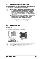
... socket contacts resulting from incorrect CPU installation/removal, or misplacement/loss/incorrect removal of the PnP cap. 2.3.1 Installing the CPU To install a CPU: 1. Contact your retailer immediately if the PnP cap is on your left. ASUS will shoulder the cost of the...installing the motherboard. 2.3 Central Processing Unit (CPU) The motherboard comes with the cap on the LGA775 socket. • The product warranty does not cover damage to the PnP cap/socket contacts/motherboard components. ASUS P5GDC-V Deluxe 2-7 ASUS will process Return Merchandise Authorization (RMA) requests ...
... socket contacts resulting from incorrect CPU installation/removal, or misplacement/loss/incorrect removal of the PnP cap. 2.3.1 Installing the CPU To install a CPU: 1. Contact your retailer immediately if the PnP cap is on your left. ASUS will shoulder the cost of the...installing the motherboard. 2.3 Central Processing Unit (CPU) The motherboard comes with the cap on the LGA775 socket. • The product warranty does not cover damage to the PnP cap/socket contacts/motherboard components. ASUS P5GDC-V Deluxe 2-7 ASUS will process Return Merchandise Authorization (RMA) requests ...

User Manual
Page 28
Lift the load plate with your thumb and forefinger to the socket pins, do not remove the PnP cap unless you . 2. To prevent damage to a 100º angle (A), then push the PnP cap from the retention tab. Lift the load lever in the direction of the socket box should face you are installing a CPU. 3. Retention tab Load lever A B PnP Cap This side of the arrow to remove (B). B A Load plate 2-8 Chapter 2: Hardware information Press the load lever with your thumb and move it to the left until it is released from the load plate window to a 135º angle. 4.
Lift the load plate with your thumb and forefinger to the socket pins, do not remove the PnP cap unless you . 2. To prevent damage to a 100º angle (A), then push the PnP cap from the retention tab. Lift the load lever in the direction of the socket box should face you are installing a CPU. 3. Retention tab Load lever A B PnP Cap This side of the arrow to remove (B). B A Load plate 2-8 Chapter 2: Hardware information Press the load lever with your thumb and move it to the left until it is released from the load plate window to a 135º angle. 4.

User Manual
Page 29
... the connectors on Hyper-Threading Technology, visit www.intel.com/info/hyperthreading. DO NOT force the CPU into the retention tab. Notes on the bottom-left corner of the socket. ASUS P5GDC-V Deluxe 2-9 A B Alignment key Gold triangle mark The CPU fits in the 775-land package with Hyper-Threading Technology. • Hyper-Threading Technology is...
... the connectors on Hyper-Threading Technology, visit www.intel.com/info/hyperthreading. DO NOT force the CPU into the retention tab. Notes on the bottom-left corner of the socket. ASUS P5GDC-V Deluxe 2-9 A B Alignment key Gold triangle mark The CPU fits in the 775-land package with Hyper-Threading Technology. • Hyper-Threading Technology is...
User Manual
Page 30
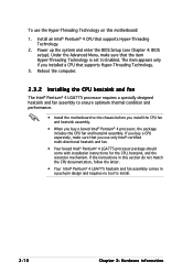
...sure that the item Hyper-Threading Technology is set to install. 2-10 Chapter 2: Hardware information Reboot the computer. 2.3.2 Installing the CPU heatsink and fan The Intel® Pentium® 4 LGA775 processor requires a specially designed heatsink and fan assembly to ensure optimum thermal... boxed Intel® Pentium® 4 LGA775 processor package should come with installation instructions for the CPU, heatsink, and the retention mechanism. Install an Intel® Pentium® 4 CPU that supports Hyper-Threading Technology. 3. Power up the system and enter the BIOS Setup (see ...
...sure that the item Hyper-Threading Technology is set to install. 2-10 Chapter 2: Hardware information Reboot the computer. 2.3.2 Installing the CPU heatsink and fan The Intel® Pentium® 4 LGA775 processor requires a specially designed heatsink and fan assembly to ensure optimum thermal... boxed Intel® Pentium® 4 LGA775 processor package should come with installation instructions for the CPU, heatsink, and the retention mechanism. Install an Intel® Pentium® 4 CPU that supports Hyper-Threading Technology. 3. Power up the system and enter the BIOS Setup (see ...

User Manual
Page 31
Place the heatsink on the motherboard. Push each of the installed CPU, making sure that the four pins match the holes on top of the pins downward to lock. ASUS P5GDC-V Deluxe 2-11 Push pin Motherboard hole 2. Rotate the push-pins clockwise to secure the heatsink and fan assembly in place. 3. To install the CPU heatsink and fan: 1.
Place the heatsink on the motherboard. Push each of the installed CPU, making sure that the four pins match the holes on top of the pins downward to lock. ASUS P5GDC-V Deluxe 2-11 Push pin Motherboard hole 2. Rotate the push-pins clockwise to secure the heatsink and fan assembly in place. 3. To install the CPU heatsink and fan: 1.

User Manual
Page 32
CPU_FAN1 P5GDC-V Do not forget to the connector on the motherboard labeled CPU_FAN1. When the fan and heatsink assembly is in place, connect the CPU fan cable to connect the CPU fan connector! Hardware monitoring errors can occur if you fail to plug this connector. 2-12 Chapter 2: Hardware information GND CPU FAN PWR CPU FAN IN CPU FAN PWM 4.
CPU_FAN1 P5GDC-V Do not forget to the connector on the motherboard labeled CPU_FAN1. When the fan and heatsink assembly is in place, connect the CPU fan cable to connect the CPU fan connector! Hardware monitoring errors can occur if you fail to plug this connector. 2-12 Chapter 2: Hardware information GND CPU FAN PWR CPU FAN IN CPU FAN PWM 4.

User Manual
Page 44
Plug the power cord and turn ON the computer. 6. P5GDC-V P5GDC-V Clear RTC RAM CLRTC1 12 23 Normal (Default) Clear CMOS You do not need to clear the RTC when the system hangs due to pins 2-3. ... such as system passwords. 2.6 Jumpers 1. Keep the cap on CLRTC jumper default position. Clear RTC RAM (CLRTC1) This jumper allows you to overclocking, use the C.P.R. (CPU Parameter Recall) feature.
Plug the power cord and turn ON the computer. 6. P5GDC-V P5GDC-V Clear RTC RAM CLRTC1 12 23 Normal (Default) Clear CMOS You do not need to clear the RTC when the system hangs due to pins 2-3. ... such as system passwords. 2.6 Jumpers 1. Keep the cap on CLRTC jumper default position. Clear RTC RAM (CLRTC1) This jumper allows you to overclocking, use the C.P.R. (CPU Parameter Recall) feature.

User Manual
Page 45
... system would not power up (3-pin USBPW12, USBPW34, USBPW56, USBPW78) Set these jumpers to +5V to CPU, DRAM in slow refresh, power supply in reduced power mode). Set to +5VSB to wake up from ... ports. USBPW12 USBPW34 3 2 2 1 +5V (Default) +5VSB P5GDC-V USBPW56 USBPW78 12 23 +5V P5GDC-V USB device wake-up (Default) +5VSB • The USB device wake-up the computer from S1 sleep mode (CPU stopped, DRAM refreshed, system running in sleep mode. 2 . The ...5VSB) whether under normal condition or in low power mode) using the connected USB devices. ASUS P5GDC-V Deluxe 2-25
... system would not power up (3-pin USBPW12, USBPW34, USBPW56, USBPW78) Set these jumpers to +5V to CPU, DRAM in slow refresh, power supply in reduced power mode). Set to +5VSB to wake up from ... ports. USBPW12 USBPW34 3 2 2 1 +5V (Default) +5VSB P5GDC-V USBPW56 USBPW78 12 23 +5V P5GDC-V USB device wake-up (Default) +5VSB • The USB device wake-up the computer from S1 sleep mode (CPU stopped, DRAM refreshed, system running in sleep mode. 2 . The ...5VSB) whether under normal condition or in low power mode) using the connected USB devices. ASUS P5GDC-V Deluxe 2-25

User Manual
Page 52
... cable matches the ground pin of 1 A ~ 3.48 A (41.76 W max.) at +12 V. GND CPU FAN PWR CPU FAN IN CPU FAN PWM CPU_FAN1 P5GDC-V P5GDC-V Fan connectors PWR_FAN1 Rotation +12V GND CHA_FAN2 Rotation +12V GND CHA_FAN1 Rotation +12V GND Only the CHA_FAN1 connector supports ...the ASUS Q-Fan 2 feature. 2-32 Chapter 2: Hardware information CPU, Chassis, and Power fan connectors (4-pin CPU_FAN, 3-pin PWR_FAN, ...
... cable matches the ground pin of 1 A ~ 3.48 A (41.76 W max.) at +12 V. GND CPU FAN PWR CPU FAN IN CPU FAN PWM CPU_FAN1 P5GDC-V P5GDC-V Fan connectors PWR_FAN1 Rotation +12V GND CHA_FAN2 Rotation +12V GND CHA_FAN1 Rotation +12V GND Only the CHA_FAN1 connector supports ...the ASUS Q-Fan 2 feature. 2-32 Chapter 2: Hardware information CPU, Chassis, and Power fan connectors (4-pin CPU_FAN, 3-pin PWR_FAN, ...

User Manual
Page 54
... +12V DC GND +12V DC P5GDC-V ATX power connectors EATXPWR +3 Volts +12 Volts +12 Volts +5V Standby Power OK Ground +5 Volts Ground +5 Volts Ground +3 Volts +3 Volts Ground +5 Volts +5 Volts +5 Volts -5 Volts ... not boot up if the power is inadequate. • The ATX 12 V Specification 2.0-compliant PSU passed the motherboard power requirement test with the following configuration: CPU : Memory : Graphics card : Parallel ATA devices : Serial ATA device : Optical drives : SCSI devices : Intel® Pentium® 4 3.6 GHz 512 MB DDR (x 4) PCI Express x16 Nvidia...
... +12V DC GND +12V DC P5GDC-V ATX power connectors EATXPWR +3 Volts +12 Volts +12 Volts +5V Standby Power OK Ground +5 Volts Ground +5 Volts Ground +3 Volts +3 Volts Ground +5 Volts +5 Volts +5 Volts -5 Volts ... not boot up if the power is inadequate. • The ATX 12 V Specification 2.0-compliant PSU passed the motherboard power requirement test with the following configuration: CPU : Memory : Graphics card : Parallel ATA devices : Serial ATA device : Optical drives : SCSI devices : Intel® Pentium® 4 3.6 GHz 512 MB DDR (x 4) PCI Express x16 Nvidia...

User Manual
Page 81
4.3.6 System Information This menu gives you an overview of the general system specifications. AMIBIOS Version : 08.00.10 Build Date : 06/18/04 Processor Type Speed Count : Genuine Intel(R) CPU 3.20 GHz : 3200 MHz : 1 System Memory Size : 248 MB AMI BIOS Displays the auto-detected BIOS information Processor Displays the auto-detected CPU specification System Memory Displays the auto-detected system memory ASUS P5GDC-V Deluxe 4-17 The BIOS automatically detects the items in this menu.
4.3.6 System Information This menu gives you an overview of the general system specifications. AMIBIOS Version : 08.00.10 Build Date : 06/18/04 Processor Type Speed Count : Genuine Intel(R) CPU 3.20 GHz : 3200 MHz : 1 System Memory Size : 248 MB AMI BIOS Displays the auto-detected BIOS information Processor Displays the auto-detected CPU specification System Memory Displays the auto-detected system memory ASUS P5GDC-V Deluxe 4-17 The BIOS automatically detects the items in this menu.


