User Manual
Page 10
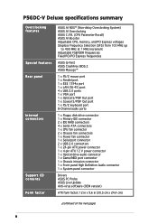
... Out port 1 x PS/2 keyboard port 8-Channel audio ports 1 x Floppy disk drive connector 1 x Primary IDE connector 2 x IDE RAID connectors 4 x Serial ATA connectors 1 x CPU fan connector 2 x Chassis fan connectors 1 x Power fan connector 1 x Serial port connector 2 x USB 2.0 connectors 1 x 24-pin ATX power connector 1 x 4-pin ATX 12 V power connector 1 x Optical drive audio connector 1 x Game/MIDI port connector 1 x Chassis intrusion connector 1 x Front panel High Definition Audio connector 1 x System panel connector Drivers ASUS PC Probe ASUS Live Update Anti-virus software (OEM version) ATX...
... Out port 1 x PS/2 keyboard port 8-Channel audio ports 1 x Floppy disk drive connector 1 x Primary IDE connector 2 x IDE RAID connectors 4 x Serial ATA connectors 1 x CPU fan connector 2 x Chassis fan connectors 1 x Power fan connector 1 x Serial port connector 2 x USB 2.0 connectors 1 x 24-pin ATX power connector 1 x 4-pin ATX 12 V power connector 1 x Optical drive audio connector 1 x Game/MIDI port connector 1 x Chassis intrusion connector 1 x Front panel High Definition Audio connector 1 x System panel connector Drivers ASUS PC Probe ASUS Live Update Anti-virus software (OEM version) ATX...
User Manual
Page 30
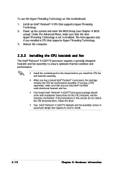
... fan assembly comes in this motherboard: 1. Under the Advanced Menu, make sure that the item Hyper-Threading Technology is set to the chassis before you install the CPU fan and heatsink assembly. • When you buy a CPU separately, make sure that you installed a CPU that supports Hyper-Threading Technology. 2. Install an Intel® Pentium® 4 CPU that supports Hyper-Threading Technology. 3. Power up the system and enter the BIOS Setup (see Chapter 4: BIOS setup). To use...
... fan assembly comes in this motherboard: 1. Under the Advanced Menu, make sure that the item Hyper-Threading Technology is set to the chassis before you install the CPU fan and heatsink assembly. • When you buy a CPU separately, make sure that you installed a CPU that supports Hyper-Threading Technology. 2. Install an Intel® Pentium® 4 CPU that supports Hyper-Threading Technology. 3. Power up the system and enter the BIOS Setup (see Chapter 4: BIOS setup). To use...
User Manual
Page 41
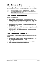
... system and change the necessary BIOS settings, if any. Turn on the slot. 5. 2.5 Expansion slots In the future, you may cause you physical injury and damage motherboard components. 2.5.1 Installing an expansion card To install an expansion card: 1. Make sure to install expansion cards. Failure to do so may need to unplug the power cord before adding or removing expansion cards. ASUS P5GDC-V Deluxe 2-21 See Chapter 4 for later use . The following...
... system and change the necessary BIOS settings, if any. Turn on the slot. 5. 2.5 Expansion slots In the future, you may cause you physical injury and damage motherboard components. 2.5.1 Installing an expansion card To install an expansion card: 1. Make sure to install expansion cards. Failure to do so may need to unplug the power cord before adding or removing expansion cards. ASUS P5GDC-V Deluxe 2-21 See Chapter 4 for later use . The following...

User Manual
Page 43
ASUS P5GDC-V Deluxe 2-23 The figure shows a network card installed on the PCI Express x16 slot. This motherboard supports PCI Express x1 network cards, SCSI cards and other cards that comply with the PCI Express specifications. 2.5.4 PCI slots 2.5.5 PCI Express x1 slot The PCI slots support cards such as a LAN card, SCSI card, USB card, and other cards that comply with the PCI Express specifications. The figure shows a LAN card installed on the PCI-Express x16 slot. The figure shows an optional DVI-ADD2 card installed on a PCI slot. A DVI-ADD2 card supports digital...
ASUS P5GDC-V Deluxe 2-23 The figure shows a network card installed on the PCI Express x16 slot. This motherboard supports PCI Express x1 network cards, SCSI cards and other cards that comply with the PCI Express specifications. 2.5.4 PCI slots 2.5.5 PCI Express x1 slot The PCI slots support cards such as a LAN card, SCSI card, USB card, and other cards that comply with the PCI Express specifications. The figure shows a LAN card installed on the PCI-Express x16 slot. The figure shows an optional DVI-ADD2 card installed on a PCI slot. A DVI-ADD2 card supports digital...

User Manual
Page 47
...connection ACT/LINK SPEED LED LED LAN port 5 . This port connects a tape, CD, DVD player, or other devices. 3 . This port is for audio/video devices, storage peripherals, PCs, or portable devices. 4 . Refer to a Local Area Network (LAN) through a network hub. S i d e S p e a k e r O u t p o r t ( b l a c k ) . L i n e O u t p o r t ( l i m e ) . This port connects a headphone or a speaker. 2.7 Connectors 2.7.1 Rear panel connectors 1 2 3 45 6 7 8 9 16 15 14 13 12 11 10 1 . P a r a l l e l p o r t . I n p o r t ( l i g h t b l u e ) . In 4-channel, 6-channel...
...connection ACT/LINK SPEED LED LED LAN port 5 . This port connects a tape, CD, DVD player, or other devices. 3 . This port is for audio/video devices, storage peripherals, PCs, or portable devices. 4 . Refer to a Local Area Network (LAN) through a network hub. S i d e S p e a k e r O u t p o r t ( b l a c k ) . L i n e O u t p o r t ( l i m e ) . This port connects a headphone or a speaker. 2.7 Connectors 2.7.1 Rear panel connectors 1 2 3 45 6 7 8 9 16 15 14 13 12 11 10 1 . P a r a l l e l p o r t . I n p o r t ( l i g h t b l u e ) . In 4-channel, 6-channel...
User Manual
Page 50
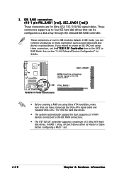
... IDE mode by default. 3. These connectors are for details. In RAID 1 array, set using these connectors such as boot/data hard disk drives or optical drives. In IDE mode, you have connected the Ultra ATA signal cable and installed Ultra ATA 133/100/66 hard disk drives. • The system automatically assigns the boot sequence of ATAPI devices connected to RAID Mode. PRI_RAID1 PIN 1 P5GDC-V RAID connectors • Before creating a RAID set both drives either as a disk array through the onboard IDE RAID controller. These connectors support up to four IDE hard disk drives...
... IDE mode by default. 3. These connectors are for details. In RAID 1 array, set using these connectors such as boot/data hard disk drives or optical drives. In IDE mode, you have connected the Ultra ATA signal cable and installed Ultra ATA 133/100/66 hard disk drives. • The system automatically assigns the boot sequence of ATAPI devices connected to RAID Mode. PRI_RAID1 PIN 1 P5GDC-V RAID connectors • Before creating a RAID set both drives either as a disk array through the onboard IDE RAID controller. These connectors support up to four IDE hard disk drives...
User Manual
Page 66
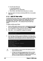
... that contains the BIOS file to prevent system boot failure! • A "Floppy not found ! To update the BIOS using a DOS-based utility. Press + during the Power-On Self Tests (POST). EZFlash starting BIOS update Checking for floppy... 4. EZFlash starting BIOS update Checking for floppy... Completed. Rebooting. • Do not shutdown or reset the system while updating the BIOS to the floppy disk drive. error message appears if the correct BIOS file is not found in the BIOS chip so it...
... that contains the BIOS file to prevent system boot failure! • A "Floppy not found ! To update the BIOS using a DOS-based utility. Press + during the Power-On Self Tests (POST). EZFlash starting BIOS update Checking for floppy... 4. EZFlash starting BIOS update Checking for floppy... Completed. Rebooting. • Do not shutdown or reset the system while updating the BIOS to the floppy disk drive. error message appears if the correct BIOS file is not found in the BIOS chip so it...
User Manual
Page 71
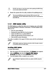
...; Update the BIOS from an updated BIOS file • Update the BIOS directly from the Internet, and • View the BIOS version information. ASUS Update requires an Internet connection either through a network or an Internet Service Provider (ISP). The recovered BIOS may not be the latest BIOS version for the U t i l i t i e s screen menu. 3. This utility is copied to manage, save, and update the motherboard BIOS in the optical drive. The D r i v e r s menu appears. 2. See page 5-3 for this utility. X X . ASUS P5GDC-V Deluxe...
...; Update the BIOS from an updated BIOS file • Update the BIOS directly from the Internet, and • View the BIOS version information. ASUS Update requires an Internet connection either through a network or an Internet Service Provider (ISP). The recovered BIOS may not be the latest BIOS version for the U t i l i t i e s screen menu. 3. This utility is copied to manage, save, and update the motherboard BIOS in the optical drive. The D r i v e r s menu appears. 2. See page 5-3 for this utility. X X . ASUS P5GDC-V Deluxe...

User Manual
Page 78
... (Device, Vendor, Size, LBA Mode, Block Mode, PIO Mode, Async DMA, Ultra DMA, and SMART monitoring). Setting to display the IDE device information. Configuration options: [Disabled] [Auto] 4-14 Chapter 4: BIOS setup These items show N/A if no IDE device is either a ZIP, LS-120, or MO drive. Select ARMD (ATAPI Removable Media Device) if your device is installed in the system. Type [Auto] Selects the type of IDE devices. Configuration options: [Not Installed] [Auto] [CDROM] [ARMD] LBA/Large Mode [Auto] Enables or disables the LBA mode. When set to [Disabled], the...
... (Device, Vendor, Size, LBA Mode, Block Mode, PIO Mode, Async DMA, Ultra DMA, and SMART monitoring). Setting to display the IDE device information. Configuration options: [Disabled] [Auto] 4-14 Chapter 4: BIOS setup These items show N/A if no IDE device is either a ZIP, LS-120, or MO drive. Select ARMD (ATAPI Removable Media Device) if your device is installed in the system. Type [Auto] Selects the type of IDE devices. Configuration options: [Not Installed] [Auto] [CDROM] [ARMD] LBA/Large Mode [Auto] Enables or disables the LBA mode. When set to [Disabled], the...

User Manual
Page 79
Configure SATA As [Standard IDE] Sets the Serial ATA configuration. Configuration options: [Auto] [Disabled] [Enabled] 32Bit Data Transfer [Disabled] Enables or disables 32-bit data transfer. Configuration options: [Disabled] [Enabled] 4.3.5 IDE Configuration The items in this menu allow you want to Native mode. Configuration options: [Disabled] [Compatible Mode] [Enhanced Mode] ASUS P5GDC-V Deluxe 4-15 Select an item then press if you to set or change the configurations for the IDE devices installed in Advanced Host Controller Interface (AHCI) or RAID mode the SATA controller ...
Configure SATA As [Standard IDE] Sets the Serial ATA configuration. Configuration options: [Auto] [Disabled] [Enabled] 32Bit Data Transfer [Disabled] Enables or disables 32-bit data transfer. Configuration options: [Disabled] [Enabled] 4.3.5 IDE Configuration The items in this menu allow you want to Native mode. Configuration options: [Disabled] [Compatible Mode] [Enhanced Mode] ASUS P5GDC-V Deluxe 4-15 Select an item then press if you to set or change the configurations for the IDE devices installed in Advanced Host Controller Interface (AHCI) or RAID mode the SATA controller ...

User Manual
Page 80
... S A T A. In this setting, you may use native OS on the Parallel ATA ports o n l y i f you did not install any of these options and encounter problems, revert to Standard IDE. ALPE and ASP [Disabled] Enables or disables the ALPE and ASP. Configuration options: [Disabled] [Enabled] AHCI Port 3 Interlock Switch [Disabled] Enables or disables the Advanced Host Controller Interface (AHCI) Port 3 interlock switch. Onboard Serial-ATA BOOTROOM [Disabled] Enables or disables the onboard Serial ATA boot ROM. If you do not change the default setting for better OS compatibility.
... S A T A. In this setting, you may use native OS on the Parallel ATA ports o n l y i f you did not install any of these options and encounter problems, revert to Standard IDE. ALPE and ASP [Disabled] Enables or disables the ALPE and ASP. Configuration options: [Disabled] [Enabled] AHCI Port 3 Interlock Switch [Disabled] Enables or disables the Advanced Host Controller Interface (AHCI) Port 3 interlock switch. Onboard Serial-ATA BOOTROOM [Disabled] Enables or disables the onboard Serial ATA boot ROM. If you do not change the default setting for better OS compatibility.

User Manual
Page 87
... CMOS Setting: VID CMOS Setting: Microcode Updating: Max CPUID Value Limit: Enhanced C1 Control CPU Internal Thermal Control Hyper Threading Technology [ 8] [ 62] [Enabled] [Disabled] [Auto] [Auto] [Enabled] Sets the ratio between the CPU Core Clock and the Front Side Bus frequency. If detected, the USB controller legacy mode is disabled. Setting to Auto allows the system to adjust the values. The default value of USB devices at startup. Use the or keys to detect the presence of this menu show the CPU-related information that the BIOS...
... CMOS Setting: VID CMOS Setting: Microcode Updating: Max CPUID Value Limit: Enhanced C1 Control CPU Internal Thermal Control Hyper Threading Technology [ 8] [ 62] [Enabled] [Disabled] [Auto] [Auto] [Enabled] Sets the ratio between the CPU Core Clock and the Front Side Bus frequency. If detected, the USB controller legacy mode is disabled. Setting to Auto allows the system to adjust the values. The default value of USB devices at startup. Use the or keys to detect the presence of this menu show the CPU-related information that the BIOS...

User Manual
Page 88
...run. In C1E mode, the CPU power consumption is auto-detected by BIOS. Configuration options: [Auto] [Disabled] CPU Internal Thermal Control [Auto] Disables or sets the CPU internal thermal control. Configuration options: [Disabled] [Enabled] Enhanced C1 Control [Auto] When set the VID CMOS setting at which the processor is to enable the C1E support. Configuration options: [Disabled] [Enabled] 4-24 Chapter 4: BIOS setup The default value of this item to the CPU documentation for details. Configuration options: [Auto] [Disabled] Hyper Threading Technology [Enabled] Allows you to...
...run. In C1E mode, the CPU power consumption is auto-detected by BIOS. Configuration options: [Auto] [Disabled] CPU Internal Thermal Control [Auto] Disables or sets the CPU internal thermal control. Configuration options: [Disabled] [Enabled] Enhanced C1 Control [Auto] When set the VID CMOS setting at which the processor is to enable the C1E support. Configuration options: [Disabled] [Enabled] 4-24 Chapter 4: BIOS setup The default value of this item to the CPU documentation for details. Configuration options: [Auto] [Disabled] Hyper Threading Technology [Enabled] Allows you to...

User Manual
Page 89
... manually set according to display the sub-menu. DRAM CAS# Latency [3 Clocks] Controls the latency between the DDR SDRAM active command and the read command and the time the data actually becomes available. Advanced Chipset Settings Configure DRAM Timing by SPD [Enabled] Graphic Adapter Priority Internal Graphics Mode Select Fixed Graphic Memory Size DVMT Graphic Memory Size [PCI Express/Int-VGA] [Enabled, 8 MB] [32 MB] [32 MB] PEG Buffer Length Link Latency PEG Root Control Slot Power [Auto] [Auto] [Auto] [Auto] Enable or disable DRAM timing. Configuration options: [2 Clocks...
... manually set according to display the sub-menu. DRAM CAS# Latency [3 Clocks] Controls the latency between the DDR SDRAM active command and the read command and the time the data actually becomes available. Advanced Chipset Settings Configure DRAM Timing by SPD [Enabled] Graphic Adapter Priority Internal Graphics Mode Select Fixed Graphic Memory Size DVMT Graphic Memory Size [PCI Express/Int-VGA] [Enabled, 8 MB] [32 MB] [32 MB] PEG Buffer Length Link Latency PEG Root Control Slot Power [Auto] [Auto] [Auto] [Auto] Enable or disable DRAM timing. Configuration options: [2 Clocks...

User Manual
Page 91
...RAID controller operating mode. Configuration options: [Standard Mode] [Quick Mode] ASUS P5GDC-V Deluxe 4-27 Configuration options: [Enabled] [Disabled] Front Panel Support Type [AC97] Allows you to IDE Mode. If the devices installed on the front panel audio module support. Configuration options: [Enabled] [Disabled] OnBoard LAN [Enabled] Allows you to Enabled. This item appears only when the ITE8212F Controller is set this item to Standard Mode to enable or disable the onboard PCI Express Gigabit LAN controller. Configuration options: [Enabled] [Disabled] LAN Option ROM...
...RAID controller operating mode. Configuration options: [Standard Mode] [Quick Mode] ASUS P5GDC-V Deluxe 4-27 Configuration options: [Enabled] [Disabled] Front Panel Support Type [AC97] Allows you to IDE Mode. If the devices installed on the front panel audio module support. Configuration options: [Enabled] [Disabled] OnBoard LAN [Enabled] Allows you to Enabled. This item appears only when the ITE8212F Controller is set this item to Standard Mode to enable or disable the onboard PCI Express Gigabit LAN controller. Configuration options: [Enabled] [Disabled] LAN Option ROM...
User Manual
Page 96
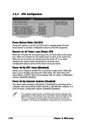
... Configuration Power Button Mode [On/Off] Restore on AC Power Loss [Power Off] Power On By RTC Alarm [Disabled] Power On By External Modems [Disabled] Power On By PCI Devices [Disabled] Power On By PS/2 Keyboard [Disabled] Keyboard Wakeup Password : Not Installed Power On By PS/2 Mouse [Disabled] Go into On/Off or Suspend when Power button is off causes an initialization string that turns the system on. 4-32 Chapter 4: BIOS setup When this item is set to Enabled...
... Configuration Power Button Mode [On/Off] Restore on AC Power Loss [Power Off] Power On By RTC Alarm [Disabled] Power On By External Modems [Disabled] Power On By PCI Devices [Disabled] Power On By PS/2 Keyboard [Disabled] Keyboard Wakeup Password : Not Installed Power On By PS/2 Mouse [Disabled] Go into On/Off or Suspend when Power button is off causes an initialization string that turns the system on. 4-32 Chapter 4: BIOS setup When this item is set to Enabled...
User Manual
Page 102
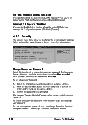
Configuration options: [Disabled] [Enabled] 4.6.3 Security The Security menu items allow you successfully set a password, this function allows the option ROMs to change password. Security Settings Supervisor Password : Not Installed User Password : Not Installed Change Supervisor Password Boot Sector Virus Protection [Disabled] to disabled password. Confirm the password when prompted. To clear the supervisor password, select the Change Supervisor Password then press . The message "Password Uninstalled" appears. 4-38 Chapter 4: BIOS setup The Supervisor Password item...
Configuration options: [Disabled] [Enabled] 4.6.3 Security The Security menu items allow you successfully set a password, this function allows the option ROMs to change password. Security Settings Supervisor Password : Not Installed User Password : Not Installed Change Supervisor Password Boot Sector Virus Protection [Disabled] to disabled password. Confirm the password when prompted. To clear the supervisor password, select the Change Supervisor Password then press . The message "Password Uninstalled" appears. 4-38 Chapter 4: BIOS setup The Supervisor Password item...
User Manual
Page 109
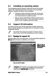
....asus.com) for updates. 5.2.1 Running the support CD Place the support CD to run the CD. The CD automatically displays the D r i v e r s menu if Autorun is NOT enabled in your hardware. • Motherboard settings and hardware options vary. Double-click the A S S E T U P . E X E to the optical drive. Use the setup procedures presented in your OS documentation for detailed information. • Make sure that you can install to change...
....asus.com) for updates. 5.2.1 Running the support CD Place the support CD to run the CD. The CD automatically displays the D r i v e r s menu if Autorun is NOT enabled in your hardware. • Motherboard settings and hardware options vary. Double-click the A S S E T U P . E X E to the optical drive. Use the setup procedures presented in your OS documentation for detailed information. • Make sure that you can install to change...

User Manual
Page 110
...174; Graphics Accelerator Driver. 5-2 Chapter 5: Software support 5.2.2 Drivers menu The drivers menu shows the available device drivers if the system detects installed devices. This driver enables Plug-n-Play INF support for configuring the chipset components. User input is enabled. If you are using three different modes: interactive, silent, or unattended preload. Intel Chipset Inf Update Program This item installs the Intel® Chipset INF Update Program. Installing the driver in silent or unattended preload modes. This driver can install this utility using Windows...
...174; Graphics Accelerator Driver. 5-2 Chapter 5: Software support 5.2.2 Drivers menu The drivers menu shows the available device drivers if the system detects installed devices. This driver enables Plug-n-Play INF support for configuring the chipset components. User input is enabled. If you are using three different modes: interactive, silent, or unattended preload. Intel Chipset Inf Update Program This item installs the Intel® Chipset INF Update Program. Installing the driver in silent or unattended preload modes. This driver can install this utility using Windows...
User Manual
Page 136
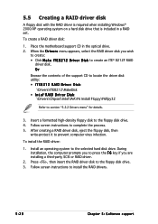
... floppy disk drive. 3. Install an operating system to the floppy disk drive. 4. Place the motherboard support CD in a RAID set. 5.5 Creating a RAID driver disk A floppy disk with the RAID driver is required when installing Windows® 2000/XP operating system on a hard disk drive that is included in the optical drive. 2. Insert a formatted high-density floppy disk to the selected hard disk drive. Follow screen instructions to complete the process. 5. To install the RAID driver: 1. To create a RAID driver disk: 1. Or Browse the contents of the support CD to locate...
... floppy disk drive. 3. Install an operating system to the floppy disk drive. 4. Place the motherboard support CD in a RAID set. 5.5 Creating a RAID driver disk A floppy disk with the RAID driver is required when installing Windows® 2000/XP operating system on a hard disk drive that is included in the optical drive. 2. Insert a formatted high-density floppy disk to the selected hard disk drive. Follow screen instructions to complete the process. 5. To install the RAID driver: 1. To create a RAID driver disk: 1. Or Browse the contents of the support CD to locate...


