
P5GD1-VM User's manual English Edition E1881
Page 5
... 2-29 2.6 Boot menu 2-31 2.6.1 Boot Device Priority 2-31 2.6.2 Boot Settings Configuration 2-32 2.6.3 Security 2-33 2.7 Exit menu 2-35 Chapter 3: Software support 3.1 Installing an operating system 3-2 3.2 Support CD information 3-2 3.2.1 Running the support CD 3-2 3.2.2 Drivers menu 3-3 3.2.3 Utilities menu 3-4 3.2.4 ASUS Contact information 3-5 3.2.5 Other information 3-6 Appendix: CPU features A.1 Intel® EM64T A-2 A.2 Enhanced Intel SpeedStep® Technology (EIST A-2 A.2.1 System requirements...
... 2-29 2.6 Boot menu 2-31 2.6.1 Boot Device Priority 2-31 2.6.2 Boot Settings Configuration 2-32 2.6.3 Security 2-33 2.7 Exit menu 2-35 Chapter 3: Software support 3.1 Installing an operating system 3-2 3.2 Support CD information 3-2 3.2.1 Running the support CD 3-2 3.2.2 Drivers menu 3-3 3.2.3 Utilities menu 3-4 3.2.4 ASUS Contact information 3-5 3.2.5 Other information 3-6 Appendix: CPU features A.1 Intel® EM64T A-2 A.2 Enhanced Intel SpeedStep® Technology (EIST A-2 A.2.1 System requirements...

P5GD1-VM User's manual English Edition E1881
Page 9
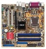
P5GD1-VM specifications summary Rear panel Internal connectors Power requirement 1 x PS/2 mouse port 1 x Parallel port 1 x LAN (RJ-45) port 8-channel audio ports 4 x USB 2.0 ports 1 x VGA port 1 x Serial ... 1 x System panel connector ATX power supply (with 24-pin and 4-pin 12 V plugs) ATX 12 V 2.0 compliant Form factor Support CD contents Micro ATX form factor: 9.6 in x 9.6 in (24.5 cm x 24.4 cm) Device drivers ASUS PC Probe ASUS Live Update Utility Anti-virus software (OEM version) *Specifications are subject to change without notice. ix
P5GD1-VM specifications summary Rear panel Internal connectors Power requirement 1 x PS/2 mouse port 1 x Parallel port 1 x LAN (RJ-45) port 8-channel audio ports 4 x USB 2.0 ports 1 x VGA port 1 x Serial ... 1 x System panel connector ATX power supply (with 24-pin and 4-pin 12 V plugs) ATX 12 V 2.0 compliant Form factor Support CD contents Micro ATX form factor: 9.6 in x 9.6 in (24.5 cm x 24.4 cm) Device drivers ASUS PC Probe ASUS Live Update Utility Anti-virus software (OEM version) *Specifications are subject to change without notice. ix
P5GD1-VM User's manual English Edition E1881
Page 11
This chapter describes the motherboard features and the new technologies it supports. 1Product introduction
This chapter describes the motherboard features and the new technologies it supports. 1Product introduction
P5GD1-VM User's manual English Edition E1881
Page 12
... for the following items. Motherboard ASUS P5GD1-VM motherboard Cables 2 x Serial ATA signal cables 1 x Ultra DMA 133/100/66 cable Floppy disk drive cable Accessories I/O shield A p p l i c a t i o n C D s ASUS motherboard support CD D o c u m e n t a t i o n User guide If any of the above items is fully compatible with Intel® 04B and 04A processors. The motherboard supports the Intel® Pentium®...
... for the following items. Motherboard ASUS P5GD1-VM motherboard Cables 2 x Serial ATA signal cables 1 x Ultra DMA 133/100/66 cable Floppy disk drive cable Accessories I/O shield A p p l i c a t i o n C D s ASUS motherboard support CD D o c u m e n t a t i o n User guide If any of the above items is fully compatible with Intel® 04B and 04A processors. The motherboard supports the Intel® Pentium®...
P5GD1-VM User's manual English Edition E1881
Page 13
...ASUS P5GD1-VM 1-3 Enhanced Intel SpeedStep® Technology (EIST) The Enhanced Intel SpeedStep® Technology (EIST) intelligently manages the CPU resources by carrying data in the 775-land package with existing PCI specifications. The GMCH provides the interface for a processor in packets. Dual display technology support... See page 2-22 and the Appendix for thinner, more workspace. Serial ATA technology The motherboard supports the Serial ATA technology through the optional ASUS DVI-ADD2 card. See page 1-27 for the latest 3D graphics, multimedia, and Internet applications...
...ASUS P5GD1-VM 1-3 Enhanced Intel SpeedStep® Technology (EIST) The Enhanced Intel SpeedStep® Technology (EIST) intelligently manages the CPU resources by carrying data in the 775-land package with existing PCI specifications. The GMCH provides the interface for a processor in packets. Dual display technology support... See page 2-22 and the Appendix for thinner, more workspace. Serial ATA technology The motherboard supports the Serial ATA technology through the optional ASUS DVI-ADD2 card. See page 1-27 for the latest 3D graphics, multimedia, and Internet applications...

P5GD1-VM User's manual English Edition E1881
Page 14
...2-5 for details. See pages 1-24 and 1-29 for details. 1.3.2 Innovative ASUS features CrashFree BIOS 2 This feature allows you to personalize and add style to use a DOS-based utility or boot from the support CD in case when the BIOS codes and data are corrupted. S/PDIF digital... This CODEC is backward compatible with customizable boot logos. No need to a fast 480 Mbps on USB 1.1 to buy a replacement ROM chip. ASUS MyLogo™ This feature allows you to powerful audio and speaker systems. See page 1-33 for details. 1-4 Chapter 1: Product introduction USB 2.0 is...
...2-5 for details. See pages 1-24 and 1-29 for details. 1.3.2 Innovative ASUS features CrashFree BIOS 2 This feature allows you to personalize and add style to use a DOS-based utility or boot from the support CD in case when the BIOS codes and data are corrupted. S/PDIF digital... This CODEC is backward compatible with customizable boot logos. No need to a fast 480 Mbps on USB 1.1 to buy a replacement ROM chip. ASUS MyLogo™ This feature allows you to powerful audio and speaker systems. See page 1-33 for details. 1-4 Chapter 1: Product introduction USB 2.0 is...

P5GD1-VM User's manual English Edition E1881
Page 20
Close the load plate (A), then A push the load lever (B) until it snaps into the socket to the Appendix for more information on the socket and damaging the CPU! 6. The CPU fits in only one correct orientation. Refer to prevent bending the connectors on these CPU features. 1-10 Chapter 1: Product introduction B The motherboard supports Intel® Pentium® 4 LGA775 processors with the Intel® Enhanced Memory 64 Technology (EM64T), Enhanced Intel SpeedStep® Technology (EIST), and Hyper-Threading Technology. DO NOT force the CPU into the retention tab.
Close the load plate (A), then A push the load lever (B) until it snaps into the socket to the Appendix for more information on the socket and damaging the CPU! 6. The CPU fits in only one correct orientation. Refer to prevent bending the connectors on these CPU features. 1-10 Chapter 1: Product introduction B The motherboard supports Intel® Pentium® 4 LGA775 processors with the Intel® Enhanced Memory 64 Technology (EM64T), Enhanced Intel SpeedStep® Technology (EIST), and Hyper-Threading Technology. DO NOT force the CPU into the retention tab.
P5GD1-VM User's manual English Edition E1881
Page 25
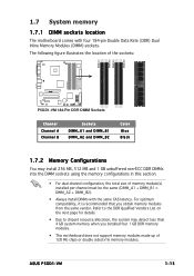
... not support memory modules made up of the sockets: P5GD1-VM DIMM_A1 DIMM_A2 DIMM_B1 DIMM_B2 ® P5GD1-VM 184-Pin DDR DIMM Sockets Channel Channel A Channel B Sockets DIMM_A1 and DIMM_B1 DIMM_A2 and DIMM_B2 Color Blue Black 1.7.2 Memory Configurations You may detect less than 4 GB system memory when you obtain memory modules from the same vendor. ASUS P5GD1-VM...
... not support memory modules made up of the sockets: P5GD1-VM DIMM_A1 DIMM_A2 DIMM_B1 DIMM_B2 ® P5GD1-VM 184-Pin DDR DIMM Sockets Channel Channel A Channel B Sockets DIMM_A1 and DIMM_B1 DIMM_A2 and DIMM_B2 Color Blue Black 1.7.2 Memory Configurations You may detect less than 4 GB system memory when you obtain memory modules from the same vendor. ASUS P5GD1-VM...

P5GD1-VM User's manual English Edition E1881
Page 26
... slots as two pairs of Dual-channel memory configuration. Visit the ASUS website (www.asus.com) for the latest DDR Qualified Vendors List. 1-16 Chapter 1: Product introduction CAS Latency DIMM support: A - supports four modules inserted into either slot, in a Single-channel memory configuration. C - supports one pair of Dual-channel memory configuration. B - DDR (400 MHz) Qualified...
... slots as two pairs of Dual-channel memory configuration. Visit the ASUS website (www.asus.com) for the latest DDR Qualified Vendors List. 1-16 Chapter 1: Product introduction CAS Latency DIMM support: A - supports four modules inserted into either slot, in a Single-channel memory configuration. C - supports one pair of Dual-channel memory configuration. B - DDR (400 MHz) Qualified...
P5GD1-VM User's manual English Edition E1881
Page 27
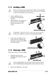
1.7.3 Installing a DIMM Make sure to avoid damaging the DIMM. 3. ASUS P5GD1-VM 1-17 DO NOT force a DIMM into the socket until the retaining clips snap back in only one direction. Failure to do so may cause severe ... that it flips out with your fingers when pressing the retaining clips. Simultaneously press the retaining clips outward to unlock the DIMM. 1 1 DDR DIMM notch Support the DIMM lightly with extra force. 2. The DIMM might get damaged when it fits in place and the DIMM is keyed with a notch so that...
1.7.3 Installing a DIMM Make sure to avoid damaging the DIMM. 3. ASUS P5GD1-VM 1-17 DO NOT force a DIMM into the socket until the retaining clips snap back in only one direction. Failure to do so may cause severe ... that it flips out with your fingers when pressing the retaining clips. Simultaneously press the retaining clips outward to unlock the DIMM. 1 1 DDR DIMM notch Support the DIMM lightly with extra force. 2. The DIMM might get damaged when it fits in place and the DIMM is keyed with a notch so that...

P5GD1-VM User's manual English Edition E1881
Page 28
... documentation that came with the slot and press firmly until the card is already installed in a chassis). 3. Remove the bracket opposite the slot that they support. Install the software drivers for information on the next page. 3. Make sure to install expansion cards. Failure to do so may cause you may need...
... documentation that came with the slot and press firmly until the card is already installed in a chassis). 3. Remove the bracket opposite the slot that they support. Install the software drivers for information on the next page. 3. Make sure to install expansion cards. Failure to do so may cause you may need...
P5GD1-VM User's manual English Edition E1881
Page 29
... PCI IDE (ITE) A B C D E F -- -- shared - - shared - -- When using PCI cards on shared slots, ensure that the drivers support "Share IRQ" or that the cards do not need IRQ assignments; shared shared - - - shared - - - - - shared - - used G H - shared -- -- -- ASUS P5GD1-VM 1-19 shared - - - shared - - - shared used - - - - IRQ assignments for ISA or PCI devices. shared shared - otherwise, conflicts will...
... PCI IDE (ITE) A B C D E F -- -- shared - - shared - -- When using PCI cards on shared slots, ensure that the drivers support "Share IRQ" or that the cards do not need IRQ assignments; shared shared - - - shared - - - - - shared - - used G H - shared -- -- -- ASUS P5GD1-VM 1-19 shared - - - shared - - - shared used - - - - IRQ assignments for ISA or PCI devices. shared shared - otherwise, conflicts will...
P5GD1-VM User's manual English Edition E1881
Page 30
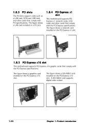
... 1-20 Chapter 1: Product introduction The figure shows a graphics card installed on the PCI Express x1 slot. 1.8.5 PCI Express x16 slot This motherboard supports PCI Express x16 graphic cards that comply with the PCI Express specifications. The figure shows a LAN card installed on the PCI-Express x16 slot.... The figure shows a DVI-ADD2 card installed on a PCI slot. 1.8.4 PCI Express x1 slot This motherboard supports PCI Express x1 network cards, SCSI cards and other cards that comply with the PCI Express specifications. 1.8.3 PCI slots The PCI slots...
... 1-20 Chapter 1: Product introduction The figure shows a graphics card installed on the PCI Express x1 slot. 1.8.5 PCI Express x16 slot This motherboard supports PCI Express x16 graphic cards that comply with the PCI Express specifications. The figure shows a LAN card installed on the PCI-Express x16 slot.... The figure shows a DVI-ADD2 card installed on a PCI slot. 1.8.4 PCI Express x1 slot This motherboard supports PCI Express x1 network cards, SCSI cards and other cards that comply with the PCI Express specifications. 1.8.3 PCI slots The PCI slots...

P5GD1-VM User's manual English Edition E1881
Page 36
...markings (usually zigzag) on the IDE cable to PIN 1. ® P5GD1-VM PCI IDE connector • The system automatically assigns the boot sequence of ATAPI devices connected to the PCI IDE connector. • The ITE® 8211F controller supports a maximum of two Ultra ATA devices. • If you attach any...disk to the PRI_PCIIDE1 connector (black) and connect an optical drive to two IDE devices (optical drive and hard disk drive). The IDE connector supports up to the PRI_IDE (blue) connector for an Ultra DMA 133/100/66 signal cables. PCI IDE connector (40-1 pin PRI_PCIIDE1) This connector...
...markings (usually zigzag) on the IDE cable to PIN 1. ® P5GD1-VM PCI IDE connector • The system automatically assigns the boot sequence of ATAPI devices connected to the PCI IDE connector. • The ITE® 8211F controller supports a maximum of two Ultra ATA devices. • If you attach any...disk to the PRI_PCIIDE1 connector (black) and connect an optical drive to two IDE devices (optical drive and hard disk drive). The IDE connector supports up to the PRI_IDE (blue) connector for an Ultra DMA 133/100/66 signal cables. PCI IDE connector (40-1 pin PRI_PCIIDE1) This connector...

P5GD1-VM User's manual English Edition E1881
Page 38
... GND CPU FAN PWR CPU FAN IN CPU FAN PWM 1-28 Chapter 1: Product introduction Connect the fan cables to the fan connectors. CHA_FAN1 CPU_FAN1 ® P5GD1-VM Fan connectors Make sure that the black wire of each cable matches the ground pin of 1 A~2.22 A (26.64 W max.) at +12V. Do not ... to connect the fan cables to the fan connectors on the fan connectors! CPU and Chassis Fan connectors (4-pin CPU_FAN1, 3-pin CHA_FAN1) The fan connectors support cooling fans of 350 mA~740 mA (8.88 W max.) or a total of the connector. Do not place jumper caps on the motherboard, making sure ...
... GND CPU FAN PWR CPU FAN IN CPU FAN PWM 1-28 Chapter 1: Product introduction Connect the fan cables to the fan connectors. CHA_FAN1 CPU_FAN1 ® P5GD1-VM Fan connectors Make sure that the black wire of each cable matches the ground pin of 1 A~2.22 A (26.64 W max.) at +12V. Do not ... to connect the fan cables to the fan connectors on the fan connectors! CPU and Chassis Fan connectors (4-pin CPU_FAN1, 3-pin CHA_FAN1) The fan connectors support cooling fans of 350 mA~740 mA (8.88 W max.) or a total of the connector. Do not place jumper caps on the motherboard, making sure ...
P5GD1-VM User's manual English Edition E1881
Page 39
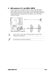
... that supports up to the USB connectors. P5GD1-VM USB+5V USB_P8USB_P8+ GND NC USB+5V USB_P6USB_P6+ GND NC ® USB56 1 P5GD1-VM USB 2.0 connectors USB78 1 USB+5V USB_P7USB_P7+ GND USB+5V USB_P5USB_P5+ GND Never connect a 1394 cable to 480 Mbps connection speed. USB connectors (10-1 pin USB56, USB78) These connectors are for USB 2.0 ports. ASUS P5GD1-VM...
... that supports up to the USB connectors. P5GD1-VM USB+5V USB_P8USB_P8+ GND NC USB+5V USB_P6USB_P6+ GND NC ® USB56 1 P5GD1-VM USB 2.0 connectors USB78 1 USB+5V USB_P7USB_P7+ GND USB+5V USB_P5USB_P5+ GND Never connect a 1394 cable to 480 Mbps connection speed. USB connectors (10-1 pin USB56, USB78) These connectors are for USB 2.0 ports. ASUS P5GD1-VM...
P5GD1-VM User's manual English Edition E1881
Page 41
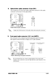
...ASUS P5GD1-VM 1-31 Optical drive audio connector (4-pin CD1) This connector is for the 4-pin audio cable that you connect a high-definition front panel audio module to the audio connector at the back of the motherboard. CD1 P5GD1-VM Left Audio Channel Ground Ground Right Audio Channel ® P5GD1-VM...-mounted front panel audio I/O module that supports either HD Audio or legacy AC'97 audio standard. Azalia-compliant Legacy AC'97-compliant pin definition pin definition GND PRESENCE# SENSE1_RETUR SENSE2_RETUR AGND NC NC NC P5GD1-VM MIC2 MICPWR Line out_R NC Line out_L PORT1...
...ASUS P5GD1-VM 1-31 Optical drive audio connector (4-pin CD1) This connector is for the 4-pin audio cable that you connect a high-definition front panel audio module to the audio connector at the back of the motherboard. CD1 P5GD1-VM Left Audio Channel Ground Ground Right Audio Channel ® P5GD1-VM...-mounted front panel audio I/O module that supports either HD Audio or legacy AC'97 audio standard. Azalia-compliant Legacy AC'97-compliant pin definition pin definition GND PRESENCE# SENSE1_RETUR SENSE2_RETUR AGND NC NC NC P5GD1-VM MIC2 MICPWR Line out_R NC Line out_L PORT1...

P5GD1-VM User's manual English Edition E1881
Page 44
System panel connector (10-1 pin F_PANEL1) This connector supports several chassis-mounted functions. PWRSW F_PANEL1 ® IDELED RESET...puts the system in sleep or soft-off the system power. 1-34 Chapter 1: Product introduction PWR GND P5GD1-VM IDE_LED+ IDE_LED- Connect the HDD Activity LED cable to the HDD. • ATX power button/soft-off...pin RESET) This 2-pin connector is for system reboot without turning off mode depending on the BIOS settings. P5GD1-VM System panel connector The sytem panel connector is for easy connection. Refer to the connector description below for ...
System panel connector (10-1 pin F_PANEL1) This connector supports several chassis-mounted functions. PWRSW F_PANEL1 ® IDELED RESET...puts the system in sleep or soft-off the system power. 1-34 Chapter 1: Product introduction PWR GND P5GD1-VM IDE_LED+ IDE_LED- Connect the HDD Activity LED cable to the HDD. • ATX power button/soft-off...pin RESET) This 2-pin connector is for system reboot without turning off mode depending on the BIOS settings. P5GD1-VM System panel connector The sytem panel connector is for easy connection. Refer to the connector description below for ...

P5GD1-VM User's manual English Edition E1881
Page 46
... (BIOS) setup. 1. b. Insert the Windows® 2000 CD to the floppy disk drive. c. A S U S E Z F l a s h (Updates the BIOS using a bootable floppy disk or the motherboard support CD when the BIOS file fails or gets corrupted.) 4. Insert a 1.44 MB floppy disk to the optical drive. d. A F o r m a t 3 1 / 2 F l o p p y D i... Insert a formatted, high density 1.44 MB floppy disk into the drive. b. c. Copy the original motherboard BIOS using the ASUS Update or AFUDOS utilities. 2.1.1 Creating a bootable floppy disk 1. Select the 3 1/2 Floppy Drive icon. Do either one of ...
... (BIOS) setup. 1. b. Insert the Windows® 2000 CD to the floppy disk drive. c. A S U S E Z F l a s h (Updates the BIOS using a bootable floppy disk or the motherboard support CD when the BIOS file fails or gets corrupted.) 4. Insert a 1.44 MB floppy disk to the optical drive. d. A F o r m a t 3 1 / 2 F l o p p y D i... Insert a formatted, high density 1.44 MB floppy disk into the drive. b. c. Copy the original motherboard BIOS using the ASUS Update or AFUDOS utilities. 2.1.1 Creating a bootable floppy disk 1. Select the 3 1/2 Floppy Drive icon. Do either one of ...
P5GD1-VM User's manual English Edition E1881
Page 47
e. A:\>afudos /oOLDBIOS1.ROM Main filename Extension name ASUS P5GD1-VM 2-3 From the Open field, type D:\bootdisk\makeboot a: assuming that D: is any user-assigned filename not more than eight alphanumeric characters for the main filename and ... exactly the same as backup when the BIOS fails or gets corrupted during the updating process. Copy the AFUDOS utility (afudos.exe) from the motherboard support CD to copy the current BIOS file that the floppy disk is not write-protected and has at the prompt type: afudos /o[filename] where the...
e. A:\>afudos /oOLDBIOS1.ROM Main filename Extension name ASUS P5GD1-VM 2-3 From the Open field, type D:\bootdisk\makeboot a: assuming that D: is any user-assigned filename not more than eight alphanumeric characters for the main filename and ... exactly the same as backup when the BIOS fails or gets corrupted during the updating process. Copy the AFUDOS utility (afudos.exe) from the motherboard support CD to copy the current BIOS file that the floppy disk is not write-protected and has at the prompt type: afudos /o[filename] where the...


