
User Manual
Page 3
Contents Notices...v Safety information vi About this guide vi P5G41T-M LX2/BR specifications summary viii Chapter 1: Product introduction 1.1 Before you proceed 1-1 1.2 Motherboard overview 1-2 1.2.1 Motherboard layout 1-2 1.2.2 Layout ...Internal connectors 1-9 1.8 Software support 1-15 1.8.1 Installing an operating system 1-15 1.8.2 Support DVD information 1-15 1.8.3 ASUS Express Gate 1-16 Chapter 2: BIOS information 2.1 Managing and updating your BIOS 2-1 2.1.1 ASUS Update utility 2-1 2.1.2 ASUS EZ Flash 2 2-2 2.1.3 ASUS CrashFree BIOS 2-3 2.2 BIOS setup program 2-3 iii
Contents Notices...v Safety information vi About this guide vi P5G41T-M LX2/BR specifications summary viii Chapter 1: Product introduction 1.1 Before you proceed 1-1 1.2 Motherboard overview 1-2 1.2.1 Motherboard layout 1-2 1.2.2 Layout ...Internal connectors 1-9 1.8 Software support 1-15 1.8.1 Installing an operating system 1-15 1.8.2 Support DVD information 1-15 1.8.3 ASUS Express Gate 1-16 Chapter 2: BIOS information 2.1 Managing and updating your BIOS 2-1 2.1.1 ASUS Update utility 2-1 2.1.2 ASUS EZ Flash 2 2-2 2.1.3 ASUS CrashFree BIOS 2-3 2.2 BIOS setup program 2-3 iii

User Manual
Page 6
... local power company. • If the power supply is broken, do not try to fix it supports. • Chapter 2: BIOS information This chapter tells how to change system settings through the BIOS Setup menus. About this guide is set to or from the existing system before the signal cables are also provided... If possible, disconnect all the manuals that the power cables for the devices are unplugged before you are not sure about the voltage of the BIOS parameters are connected.
... local power company. • If the power supply is broken, do not try to fix it supports. • Chapter 2: BIOS information This chapter tells how to change system settings through the BIOS Setup menus. About this guide is set to or from the existing system before the signal cables are also provided... If possible, disconnect all the manuals that the power cables for the devices are unplugged before you are not sure about the voltage of the BIOS parameters are connected.
User Manual
Page 9
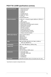
ix P5G41T-M LX2/BR specifications summary Back panel I/O ports Internal connectors ASUS unique features BIOS Manageability Support DVD Accessories Form factor 1 x PS/2 keyboard port 1 x PS/2 mouse port 1 x COM port 1 x VGA port 1 x LAN (RJ-45) port 4 x USB ...x 4-pin ATX 12V power connector 1 x Chassis intrusion connector ASUS CrashFree BIOS 3 ASUS Q-Fan ASUS EZ Flash 2 ASUS MyLogo 2 ASUS Express Gate 8Mb Flash ROM, AMI BIOS, PnP, DMI 2.0, WfM 2.0, ACPI 2.0a, SM BIOS 2.5 WOL, PXE, PME Wake up, WOR by Ring Drivers ASUS PC Probe II ASUS Update Anti-Virus software (OEM version) 2 x Serial ATA ...
ix P5G41T-M LX2/BR specifications summary Back panel I/O ports Internal connectors ASUS unique features BIOS Manageability Support DVD Accessories Form factor 1 x PS/2 keyboard port 1 x PS/2 mouse port 1 x COM port 1 x VGA port 1 x LAN (RJ-45) port 4 x USB ...x 4-pin ATX 12V power connector 1 x Chassis intrusion connector ASUS CrashFree BIOS 3 ASUS Q-Fan ASUS EZ Flash 2 ASUS MyLogo 2 ASUS Express Gate 8Mb Flash ROM, AMI BIOS, PnP, DMI 2.0, WfM 2.0, ACPI 2.0a, SM BIOS 2.5 WOL, PXE, PME Wake up, WOR by Ring Drivers ASUS PC Probe II ASUS Update Anti-Virus software (OEM version) 2 x Serial ATA ...

User Manual
Page 11
... RTL 8112L AUDIO ICS 9LPRS441 Intel® G41 PCIEX1_1 Lithium Cell CMOS Power PRI_IDE 7 2 24.4cm(9.6in) EATXPWR Super PCIEX16 I/O 16 P5G41T-M LX2/BR SATA4 SATA3 8Mb PCI1 Intel® SATA2 BIOS SATA1 ICH7 PCI2 8 VIA VT1705 CD SB_PWR USBPW5-8 USB56 USB78 CLRTC AAFP CHASSIS F_PANEL 15 14 4 13 12 11 10 9 Place six...
... RTL 8112L AUDIO ICS 9LPRS441 Intel® G41 PCIEX1_1 Lithium Cell CMOS Power PRI_IDE 7 2 24.4cm(9.6in) EATXPWR Super PCIEX16 I/O 16 P5G41T-M LX2/BR SATA4 SATA3 8Mb PCI1 Intel® SATA2 BIOS SATA1 ICH7 PCI2 8 VIA VT1705 CD SB_PWR USBPW5-8 USB56 USB78 CLRTC AAFP CHASSIS F_PANEL 15 14 4 13 12 11 10 9 Place six...
User Manual
Page 13
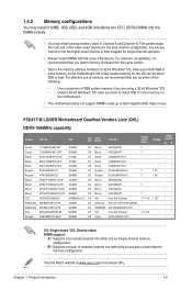
...if you are using a 32-bit Windows® OS. - P5G41T-M LX2/BR Motherboard Qualified Vendors Lists (QVL) DDR3-1066MHz capability Vendor Part No... Heat-Sink Package Samsung SEC 901 HCF8 K4B1G0846E SAMSUNG 846 K4B2G0846B-HCF8 N/A Heat-Sink Package Hynix H5TQ1G83AFP G7C Timing Dimm (Bios) 7 7 7 7 7 7 7-7-7-16 7-7-7-20 Voltage 1.5V 1.5V 1.75V DIMM support A* B SS: Single-sided...Double-sided DIMM support: • A*: Supports one pair of the following: - Visit the ASUS website at www.asus.com for the OS can be about 3GB or less. 1.4.2 Memory configurations You may install 512MB...
...if you are using a 32-bit Windows® OS. - P5G41T-M LX2/BR Motherboard Qualified Vendors Lists (QVL) DDR3-1066MHz capability Vendor Part No... Heat-Sink Package Samsung SEC 901 HCF8 K4B1G0846E SAMSUNG 846 K4B2G0846B-HCF8 N/A Heat-Sink Package Hynix H5TQ1G83AFP G7C Timing Dimm (Bios) 7 7 7 7 7 7 7-7-7-16 7-7-7-20 Voltage 1.5V 1.5V 1.75V DIMM support A* B SS: Single-sided...Double-sided DIMM support: • A*: Supports one pair of the following: - Visit the ASUS website at www.asus.com for the OS can be about 3GB or less. 1.4.2 Memory configurations You may install 512MB...
User Manual
Page 14
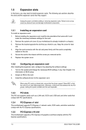
...software drivers for information on shared slots, ensure that the drivers support "Share IRQ" or that came with the PCI Express specifications. 1-5 ASUS P5G41T-M LX2/BR See Chapter 2 for the expansion card. Otherwise, conflicts will arise between the two PCI groups, making the system unstable and the card inoperable... the card connector with the slot and press firmly until the card is already installed in a chassis). 3. When using PCI cards on BIOS setup. 2. Failure to the card. 3. Assign an IRQ to do not need to the chassis with the screw you removed earlier. ...
...software drivers for information on shared slots, ensure that the drivers support "Share IRQ" or that came with the PCI Express specifications. 1-5 ASUS P5G41T-M LX2/BR See Chapter 2 for the expansion card. Otherwise, conflicts will arise between the two PCI groups, making the system unstable and the card inoperable... the card connector with the slot and press firmly until the card is already installed in a chassis). 3. When using PCI cards on BIOS setup. 2. Failure to the card. 3. Assign an IRQ to do not need to the chassis with the screw you removed earlier. ...
User Manual
Page 15
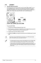
...reboot the system, then the BIOS automatically resets parameter settings to pins 1-2. 3. After clearing the CMOS, reinstall the battery. • You do not help, remove the onboard battery and move the cap back to default values. CLRTC 12 23 P5G41T-M LX2/BR Normal (Default) Clear RTC P5G41T-M LX2/BR Clear RTC RAM To erase... 2-3 for about 5-10 seconds, then move the jumper again to re-enter data. Shut down the key during the boot process and enter BIOS setup to clear the CMOS RTC RAM data. 1.6 Jumpers 1. Keep the cap on CLRTC jumper default position. Plug the power cord and turn...
...reboot the system, then the BIOS automatically resets parameter settings to pins 1-2. 3. After clearing the CMOS, reinstall the battery. • You do not help, remove the onboard battery and move the cap back to default values. CLRTC 12 23 P5G41T-M LX2/BR Normal (Default) Clear RTC P5G41T-M LX2/BR Clear RTC RAM To erase... 2-3 for about 5-10 seconds, then move the jumper again to re-enter data. Shut down the key during the boot process and enter BIOS setup to clear the CMOS RTC RAM data. 1.6 Jumpers 1. Keep the cap on CLRTC jumper default position. Plug the power cord and turn...
User Manual
Page 16
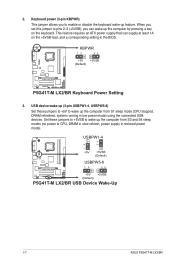
...from S1 sleep mode (CPU stopped, DRAM refreshed, system running in reduced power mode). KBPWR 12 23 +5V +5VSB (Default) P5G41T-M LX2/BR P5G41T-M LX2/BR Keyboard Power Setting 3. Set these jumpers to +5V to CPU, DRAM in slow refresh, power supply in low power mode) ...computer by pressing a key on the +5VSB lead, and a corresponding setting in the BIOS. This feature requires an ATX power supply that can wake up feature. USBPW1-4 12 23 +5V +5VSB (Default) USBPW5-8 P5G41T-M LX2/BR 12 23 +5V +5VSB (Default) P5G41T-M LX2/BR USB Device Wake-Up 1-7 ASUS P5G41T-M LX2/BR
...from S1 sleep mode (CPU stopped, DRAM refreshed, system running in reduced power mode). KBPWR 12 23 +5V +5VSB (Default) P5G41T-M LX2/BR P5G41T-M LX2/BR Keyboard Power Setting 3. Set these jumpers to +5V to CPU, DRAM in slow refresh, power supply in low power mode) ...computer by pressing a key on the +5VSB lead, and a corresponding setting in the BIOS. This feature requires an ATX power supply that can wake up feature. USBPW1-4 12 23 +5V +5VSB (Default) USBPW5-8 P5G41T-M LX2/BR 12 23 +5V +5VSB (Default) P5G41T-M LX2/BR USB Device Wake-Up 1-7 ASUS P5G41T-M LX2/BR
User Manual
Page 22
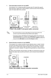
...you want to connect a high-definition front panel audio module to this connector, set the Front Panel Type item in the BIOS setup to this connector is set the item to [AC97]. The signal is for a chassis-mounted intrusion detection sensor or ... default, the pins labeled "Chassis Signal" and "GND" are shorted with a jumper cap. CHASSIS +5VSB_MB Chassis Signal GND P5G41T-M LX2/BR P5G41T-M LX2/BR Chassis intrusion connector 1-13 ASUS P5G41T-M LX2/BR Connect one end of the motherboard's high-definition audio capability. • If you intend to this connector. See section 2.4.2 ...
...you want to connect a high-definition front panel audio module to this connector, set the Front Panel Type item in the BIOS setup to this connector is set the item to [AC97]. The signal is for a chassis-mounted intrusion detection sensor or ... default, the pins labeled "Chassis Signal" and "GND" are shorted with a jumper cap. CHASSIS +5VSB_MB Chassis Signal GND P5G41T-M LX2/BR P5G41T-M LX2/BR Chassis intrusion connector 1-13 ASUS P5G41T-M LX2/BR Connect one end of the motherboard's high-definition audio capability. • If you intend to this connector. See section 2.4.2 ...
User Manual
Page 26
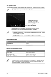
...The Splash Screen The Express Gate's splash screen appears eight seconds after you through basic Express Gate configurations including language, date, and time. 1-17 ASUS P5G41T-M LX2/BR Splash screen hot keys Key Function Power off the computer Continue booting to the existing OS when the timer above the Exit icon counts down...+ + + + Function Switch between applications Bring the Power-Off dialog box Save screen snapshots to immediately enter the existing OS • To enter the motherboard BIOS Setup program, click Exit on the splash screen and then hold down to zero (0);
...The Splash Screen The Express Gate's splash screen appears eight seconds after you through basic Express Gate configurations including language, date, and time. 1-17 ASUS P5G41T-M LX2/BR Splash screen hot keys Key Function Power off the computer Continue booting to the existing OS when the timer above the Exit icon counts down...+ + + + Function Switch between applications Bring the Power-Off dialog box Save screen snapshots to immediately enter the existing OS • To enter the motherboard BIOS Setup program, click Exit on the splash screen and then hold down to zero (0);
User Manual
Page 30
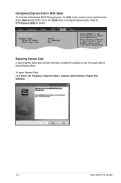
... configure Express Gate. To repair Express Gate: Click Start > All Programs > Express Gate > Express Gate Installer > Repair this software. 1-21 ASUS P5G41T-M LX2/BR Go to the Tools menu to select and update BIOS. This utility supports 1.FAT 12/16/32 (r/w) 2.NTFS (read only) 3.CD-DISC (read only) Repairing Express Gate In case Express Gate...
... configure Express Gate. To repair Express Gate: Click Start > All Programs > Express Gate > Express Gate Installer > Repair this software. 1-21 ASUS P5G41T-M LX2/BR Go to the Tools menu to select and update BIOS. This utility supports 1.FAT 12/16/32 (r/w) 2.NTFS (read only) 3.CD-DISC (read only) Repairing Express Gate In case Express Gate...
User Manual
Page 31
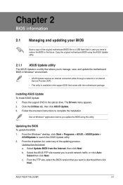
... the Utilities tab, then click ASUS Update. 3. Place the support DVD in the optical drive. Quit all Windows® applications before you to complete the installation. Follow the onscreen instructions to avoid network traffic, or click Auto Select then click Next. Select Update BIOS from the Internet a. Updating the BIOS To update the BIOS: 1. b. ASUS P5G41T-M LX2/BR 2-1
... the Utilities tab, then click ASUS Update. 3. Place the support DVD in the optical drive. Quit all Windows® applications before you to complete the installation. Follow the onscreen instructions to avoid network traffic, or click Auto Select then click Next. Select Update BIOS from the Internet a. Updating the BIOS To update the BIOS: 1. b. ASUS P5G41T-M LX2/BR 2-1
User Manual
Page 32
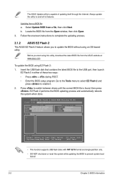
... all its features. Insert the USB flash disk that contains the latest BIOS file to update the BIOS without using an OS‑based utility. ASUSTek EZ Flash 2 BIOS ROM Utility V3.44 FLASH TYPE: MXIC 25L8005 Current ROM BOARD: P5G41T-M LX2/BR VER: 0303 (H:00 B:00) DATE: 11/30/2009 Update ROM ... with FAT 32/16 format and single partition only. • DO NOT shut down or reset the system while updating the BIOS to complete the updating process. 2.1.2 ASUS EZ Flash 2 The ASUS EZ Flash 2 feature allows you start using EZ Flash 2: 1. Before you to the USB port, then launch EZ Flash...
... all its features. Insert the USB flash disk that contains the latest BIOS file to update the BIOS without using an OS‑based utility. ASUSTek EZ Flash 2 BIOS ROM Utility V3.44 FLASH TYPE: MXIC 25L8005 Current ROM BOARD: P5G41T-M LX2/BR VER: 0303 (H:00 B:00) DATE: 11/30/2009 Update ROM ... with FAT 32/16 format and single partition only. • DO NOT shut down or reset the system while updating the BIOS to complete the updating process. 2.1.2 ASUS EZ Flash 2 The ASUS EZ Flash 2 feature allows you start using EZ Flash 2: 1. Before you to the USB port, then launch EZ Flash...
User Manual
Page 33
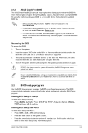
... Defaults item under the Exit menu. Entering BIOS Setup at startup To enter BIOS Setup at www.asus.com. • The removable devices that contains the BIOS file to the USB port or to enter BIOS Setup using the first two options. ASUS P5G41T-M LX2/BR 2-3 Turn off then back on. The BIOS screens include navigation keys and brief online...
... Defaults item under the Exit menu. Entering BIOS Setup at startup To enter BIOS Setup at www.asus.com. • The removable devices that contains the BIOS file to the USB port or to enter BIOS Setup using the first two options. ASUS P5G41T-M LX2/BR 2-3 Turn off then back on. The BIOS screens include navigation keys and brief online...
User Manual
Page 34
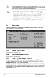
... [xx:xx:xx] Allows you to set the system time. 2.3.2 System Date [Day xx/xx/xxxx] Allows you an overview of IDE/SATA devices. The BIOS automatically detects the values opposite the dimmed items (Device, Vendor, Size, LBA Mode, Block Mode, PIO Mode, Async DMA, Ultra DMA, and SMART monitoring). ...the Exit Menu. We recommend to always shut down the system properly from a running operating system can cause damage to your screen. • Visit the ASUS website at www.asus.com to download the latest BIOS file for this motherboard apply for most conditions to ensure optimum performance.
... [xx:xx:xx] Allows you to set the system time. 2.3.2 System Date [Day xx/xx/xxxx] Allows you an overview of IDE/SATA devices. The BIOS automatically detects the values opposite the dimmed items (Device, Vendor, Size, LBA Mode, Block Mode, PIO Mode, Async DMA, Ultra DMA, and SMART monitoring). ...the Exit Menu. We recommend to always shut down the system properly from a running operating system can cause damage to your screen. • Visit the ASUS website at www.asus.com to download the latest BIOS file for this motherboard apply for most conditions to ensure optimum performance.
User Manual
Page 36
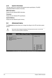
... items. Incorrect field values can cause the system to change the settings for the CPU and other system devices. Main Advanced BIOS SETUP UTILITY Power Boot Tools Exit CPU Configuration Chipset Onboard Devices Configuration USB Configuration PCIPnP Configure CPU. Take caution when changing the... F1 General Help F10 Save and Exit ESC Exit v02.61 (C)Copyright 1985-2009, American Megatrends, Inc. 2-6 Chapter 2: BIOS information 2.3.5 System Information This menu gives you to malfunction. Select Screen Select Item +- Processor Displays the auto-detected CPU specification. The...
... items. Incorrect field values can cause the system to change the settings for the CPU and other system devices. Main Advanced BIOS SETUP UTILITY Power Boot Tools Exit CPU Configuration Chipset Onboard Devices Configuration USB Configuration PCIPnP Configure CPU. Take caution when changing the... F1 General Help F10 Save and Exit ESC Exit v02.61 (C)Copyright 1985-2009, American Megatrends, Inc. 2-6 Chapter 2: BIOS information 2.3.5 System Information This menu gives you to malfunction. Select Screen Select Item +- Processor Displays the auto-detected CPU specification. The...

User Manual
Page 37
... and set to [Enabled], you to use the Enhanced Intel® SpeedStep® Technology. Configuration options: [Enabled] [Disabled] ASUS P5G41T-M LX2/BR 2-7 With virtualization, one computer system can adjust the system power settings in the operating system to use the EIST feature. Configuration options...] [Enabled] Execute-Disable Bit Capability [Enabled] Allows you installed an Intel® Pentium® 4 or later CPU that the BIOS automatically detects. Ratio CMOS Setting [Auto] Sets the ration between CPU core clock and the FSB frequency. Configuration options: [Disabled] ...
... and set to [Enabled], you to use the Enhanced Intel® SpeedStep® Technology. Configuration options: [Enabled] [Disabled] ASUS P5G41T-M LX2/BR 2-7 With virtualization, one computer system can adjust the system power settings in the operating system to use the EIST feature. Configuration options...] [Enabled] Execute-Disable Bit Capability [Enabled] Allows you installed an Intel® Pentium® 4 or later CPU that the BIOS automatically detects. Ratio CMOS Setting [Auto] Sets the ration between CPU core clock and the FSB frequency. Configuration options: [Disabled] ...
User Manual
Page 38
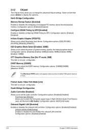
.... Configuration options: [Enabled] [Disabled] Onboard LAN Boot ROM [Disabled] Enables or disables the boot ROM in the onboard LAN controller. Configuration options: [Disabled] [Enabled] 2-8 Chapter 2: BIOS information Configuration options: [128MB] [256MB] [Maximum DVMT] The [Maximum DVMT] option only appears when you to select the front panel support type. North Bridge Configuration...
.... Configuration options: [Enabled] [Disabled] Onboard LAN Boot ROM [Disabled] Enables or disables the boot ROM in the onboard LAN controller. Configuration options: [Disabled] [Enabled] 2-8 Chapter 2: BIOS information Configuration options: [128MB] [256MB] [Maximum DVMT] The [Maximum DVMT] option only appears when you to select the front panel support type. North Bridge Configuration...
User Manual
Page 39
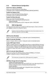
... the USB controller legacy mode is plugged in HiSpeed (480Mbps) or Full Speed (12Mbps). Configuration options: [Auto] [Floppy] [Forced FDD] [Hard Disk] [CDROM] ASUS P5G41T-M LX2/BR 2-9 Configuration options: [Normal] [EPP+ECP] [EPP] [ECP] Parallel Port IRQ [IRQ7] Allows you to change the USB-related features. Configuration options: [FullSpeed]...3F8/IRQ4] [2F8/IRQ3] [3E8/IRQ4] [2E8/IRQ3] Parallel Port Address [378] Allows you to set the maximum time that the BIOS waits for Legacy USB storage devices, including USB flash drives and USB hard drives. If no USB device is disabled.
... the USB controller legacy mode is plugged in HiSpeed (480Mbps) or Full Speed (12Mbps). Configuration options: [Auto] [Floppy] [Forced FDD] [Hard Disk] [CDROM] ASUS P5G41T-M LX2/BR 2-9 Configuration options: [Normal] [EPP+ECP] [EPP] [ECP] Parallel Port IRQ [IRQ7] Allows you to change the USB-related features. Configuration options: [FullSpeed]...3F8/IRQ4] [2F8/IRQ3] [3E8/IRQ4] [2E8/IRQ3] Parallel Port Address [378] Allows you to set the maximum time that the BIOS waits for Legacy USB storage devices, including USB flash drives and USB hard drives. If no USB device is disabled.
User Manual
Page 40
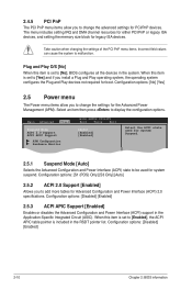
... for Advanced Configuration and Power Interface (ACPI) 2.0 specifications. Configuration options: [Disabled] [Enabled] 2-10 Chapter 2: BIOS information Main Advanced Power BIOS SETUP UTILITY Boot Tools Exit Suspend Mode [Auto] ACPI 2.0 Support [Enabled] ACPI APIC Support [Enabled] APM Configuration...ACPI state used for System Suspend. 2.5.1 Suspend Mode [Auto] Selects the Advanced Configuration and Power Interface (ACPI) state to [No], BIOS configures all the devices in the Application-Specific Integrated Circuit (ASIC). Configuration options: [S1 (POS) Only] [S3 Only] [Auto...
... for Advanced Configuration and Power Interface (ACPI) 2.0 specifications. Configuration options: [Disabled] [Enabled] 2-10 Chapter 2: BIOS information Main Advanced Power BIOS SETUP UTILITY Boot Tools Exit Suspend Mode [Auto] ACPI 2.0 Support [Enabled] ACPI APIC Support [Enabled] APM Configuration...ACPI state used for System Suspend. 2.5.1 Suspend Mode [Auto] Selects the Advanced Configuration and Power Interface (ACPI) state to [No], BIOS configures all the devices in the Application-Specific Integrated Circuit (ASIC). Configuration options: [S1 (POS) Only] [S3 Only] [Auto...


