
User Manual
Page 2
... for the GPL Software, and/or the complete corresponding source code of the LGPL Software (with you encounter any warranty. SPECIFICATIONS AND INFORMATION CONTAINED IN THIS MANUAL ARE FURNISHED FOR INFORMATIONAL USE ONLY, AND ARE SUBJECT TO CHANGE AT ANY TIME ...ASUS HAS BEEN ADVISED OF THE POSSIBILITY OF SUCH DAMAGES ARISING FROM ANY DEFECT OR ERROR IN THIS MANUAL OR PRODUCT. All Rights Reserved. Offer to obtain the corresponding source code and your request please provide the name, model number and version, as defined in writing by downloading it from http://support.asus.com/download...
... for the GPL Software, and/or the complete corresponding source code of the LGPL Software (with you encounter any warranty. SPECIFICATIONS AND INFORMATION CONTAINED IN THIS MANUAL ARE FURNISHED FOR INFORMATIONAL USE ONLY, AND ARE SUBJECT TO CHANGE AT ANY TIME ...ASUS HAS BEEN ADVISED OF THE POSSIBILITY OF SUCH DAMAGES ARISING FROM ANY DEFECT OR ERROR IN THIS MANUAL OR PRODUCT. All Rights Reserved. Offer to obtain the corresponding source code and your request please provide the name, model number and version, as defined in writing by downloading it from http://support.asus.com/download...
User Manual
Page 3
... guide vi P5G41T-M LX2/BR specifications summary viii Chapter 1: Product introduction 1.1 Before you proceed 1-1 1.2 Motherboard overview 1-2 1.2.1 Motherboard layout 1-2 1.2.2 Layout contents 1-2 1.3 Central Processing Unit (CPU 1-3 1.4 System memory 1-3 1.4.1 Overview 1-3 1.4.2 Memory configurations 1-4 1.5 Expansion slots 1-5 1.5.1 Installing an expansion card 1-5 1.5.2 Configuring an expansion card 1-5 1.5.3 PCI slots 1-5 1.5.4 PCI Express x1 slot 1-5 1.5.5 PCI Express x16 slot 1-5 1.6 Jumpers 1-6 1.7 Connectors 1-8 1.7.1 Rear panel ports 1-8 1.7.2 Internal connectors...
... guide vi P5G41T-M LX2/BR specifications summary viii Chapter 1: Product introduction 1.1 Before you proceed 1-1 1.2 Motherboard overview 1-2 1.2.1 Motherboard layout 1-2 1.2.2 Layout contents 1-2 1.3 Central Processing Unit (CPU 1-3 1.4 System memory 1-3 1.4.1 Overview 1-3 1.4.2 Memory configurations 1-4 1.5 Expansion slots 1-5 1.5.1 Installing an expansion card 1-5 1.5.2 Configuring an expansion card 1-5 1.5.3 PCI slots 1-5 1.5.4 PCI Express x1 slot 1-5 1.5.5 PCI Express x16 slot 1-5 1.6 Jumpers 1-6 1.7 Connectors 1-8 1.7.1 Rear panel ports 1-8 1.7.2 Internal connectors...
User Manual
Page 14
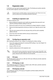
... PCI specifications. 1.5.4 PCI Express x1 slot This motherboard supports PCI Express x1 network cards, SCSI cards, and other cards that comply with the PCI Express specifications. 1.5.5 PCI Express x16 slot This motherboard supports a PCI Express x16 graphics card that complies with the slot and press firmly until the card is already installed in a chassis). 3. Remove the system unit cover (if your motherboard is completely seated on the system and change the necessary BIOS settings, if any. Align the card connector with the PCI Express specifications. 1-5 ASUS P5G41T-M LX2/BR...
... PCI specifications. 1.5.4 PCI Express x1 slot This motherboard supports PCI Express x1 network cards, SCSI cards, and other cards that comply with the PCI Express specifications. 1.5.5 PCI Express x16 slot This motherboard supports a PCI Express x16 graphics card that complies with the slot and press firmly until the card is already installed in a chassis). 3. Remove the system unit cover (if your motherboard is completely seated on the system and change the necessary BIOS settings, if any. Align the card connector with the PCI Express specifications. 1-5 ASUS P5G41T-M LX2/BR...
User Manual
Page 16
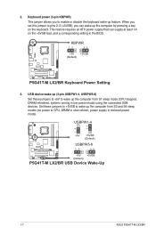
... low power mode) using the connected USB devices. Set these jumpers to +5V to pins 2-3 (+5VSB), you to enable or disable the keyboard wake-up the computer from S3 and S4 sleep modes (no power to wake up the computer by pressing a key on the +5VSB lead, and a corresponding setting in reduced power mode). USB device wake-up (3-pin USBPW1-4, USBPW5-8) Set these jumpers to +5VSB to CPU, DRAM in slow refresh, power supply in the BIOS. 2. KBPWR 12 23 +5V +5VSB (Default) P5G41T-M LX2/BR P5G41T-M LX2/BR Keyboard Power Setting 3. Keyboard power (3-pin...
... low power mode) using the connected USB devices. Set these jumpers to +5V to pins 2-3 (+5VSB), you to enable or disable the keyboard wake-up the computer from S3 and S4 sleep modes (no power to wake up the computer by pressing a key on the +5VSB lead, and a corresponding setting in reduced power mode). USB device wake-up (3-pin USBPW1-4, USBPW5-8) Set these jumpers to +5VSB to CPU, DRAM in slow refresh, power supply in the BIOS. 2. KBPWR 12 23 +5V +5VSB (Default) P5G41T-M LX2/BR P5G41T-M LX2/BR Keyboard Power Setting 3. Keyboard power (3-pin...
User Manual
Page 24
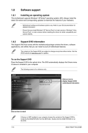
... installing the drivers for better compatibility and system stability. 1.8.2 Support DVD information The Support DVD that comes with the motherboard package contains the drivers, software applications, and utilities that you can install to the optical drive. To run the DVD. 1-15 ASUS P5G41T-M LX2/BR Always install the latest OS version and corresponding updates to maximize the features of the Support DVD are subject to your hardware. • Motherboard settings and hardware options vary. Refer to change...
... installing the drivers for better compatibility and system stability. 1.8.2 Support DVD information The Support DVD that comes with the motherboard package contains the drivers, software applications, and utilities that you can install to the optical drive. To run the DVD. 1-15 ASUS P5G41T-M LX2/BR Always install the latest OS version and corresponding updates to maximize the features of the Support DVD are subject to your hardware. • Motherboard settings and hardware options vary. Refer to change...

User Manual
Page 25
... that gives you quick access to the motherboard USB port before use Skype or other Express Gate applications without entering the Windows® OS. • The actual boot time depends on the system configuration. • Download the latest Express Gate version from the motherboard Support DVD before turning on SATA HDDs, USB HDDs, and flash drives with at www.asus.com. To install Express Gate on your computer: 1. The Drivers menu appears if Autorun is enabled on your computer...
... that gives you quick access to the motherboard USB port before use Skype or other Express Gate applications without entering the Windows® OS. • The actual boot time depends on the system configuration. • Download the latest Express Gate version from the motherboard Support DVD before turning on SATA HDDs, USB HDDs, and flash drives with at www.asus.com. To install Express Gate on your computer: 1. The Drivers menu appears if Autorun is enabled on your computer...
User Manual
Page 28
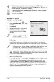
... to configure the WiFi options. on the hard disk drive. Exits ASUS Express Gate. Powers off the computer. Click Configuration Panel LaunchBar. If Security is connected to configure the static IP settings manually. Make the proper network configurations. Left-click this step. • WiFi settings (if supported) If you want to connect to a wireless network, click Setup to launch the File Manager window. Click Network. 3. Click OK to eject the removable storage device / USB drive. Right-click it to enable...
... to configure the WiFi options. on the hard disk drive. Exits ASUS Express Gate. Powers off the computer. Click Configuration Panel LaunchBar. If Security is connected to configure the static IP settings manually. Make the proper network configurations. Left-click this step. • WiFi settings (if supported) If you want to connect to a wireless network, click Setup to launch the File Manager window. Click Network. 3. Click OK to eject the removable storage device / USB drive. Right-click it to enable...
User Manual
Page 30
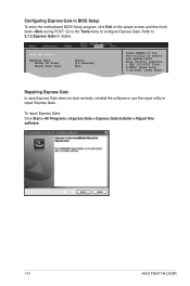
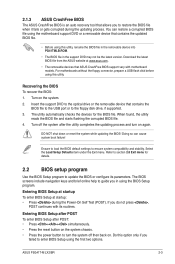
... > Express Gate > Express Gate Installer > Repair this software. 1-21 ASUS P5G41T-M LX2/BR Configuring Express Gate in BIOS Setup To enter the motherboard BIOS Setup program, click Exit on the splash screen and then hold down during POST. Go to the Tools menu to repair Express Gate. This utility supports 1.FAT 12/16/32 (r/w) 2.NTFS (read only) 3.CD-DISC (read only) Repairing Express Gate In case Express Gate does not start normally, reinstall the software or use the repair utility to configure Express Gate. Main Advanced Power BIOS SETUP UTILITY Boot...
... > Express Gate > Express Gate Installer > Repair this software. 1-21 ASUS P5G41T-M LX2/BR Configuring Express Gate in BIOS Setup To enter the motherboard BIOS Setup program, click Exit on the splash screen and then hold down during POST. Go to the Tools menu to repair Express Gate. This utility supports 1.FAT 12/16/32 (r/w) 2.NTFS (read only) 3.CD-DISC (read only) Repairing Express Gate In case Express Gate does not start normally, reinstall the software or use the repair utility to configure Express Gate. Main Advanced Power BIOS SETUP UTILITY Boot...
User Manual
Page 31
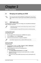
... original motherboard BIOS using this utility. Select Update BIOS from the Internet a. c. ASUS P5G41T-M LX2/BR 2-1 Installing ASUS Update To install ASUS Update: 1. Place the support DVD in the future. From the dropdown list, select any of the original motherboard BIOS file to a USB flash disk in case you need to avoid network traffic, or click Auto Select then click Next. b. Follow the onscreen instructions to launch the ASUS Update utility. 2. Chapter 2 BIOS information 2.1 Managing and updating your BIOS Save a copy of the updating process: Updating from...
... original motherboard BIOS using this utility. Select Update BIOS from the Internet a. c. ASUS P5G41T-M LX2/BR 2-1 Installing ASUS Update To install ASUS Update: 1. Place the support DVD in the future. From the dropdown list, select any of the original motherboard BIOS file to a USB flash disk in case you need to avoid network traffic, or click Auto Select then click Next. b. Follow the onscreen instructions to launch the ASUS Update utility. 2. Chapter 2 BIOS information 2.1 Managing and updating your BIOS Save a copy of the updating process: Updating from...
User Manual
Page 32
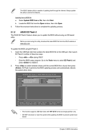
... onscreen instructions to complete the updating process. 2.1.2 ASUS EZ Flash 2 The ASUS EZ Flash 2 feature allows you start using EZ Flash 2: 1. ASUSTek EZ Flash 2 BIOS ROM Utility V3.44 FLASH TYPE: MXIC 25L8005 Current ROM BOARD: P5G41T-M LX2/BR VER: 0303 (H:00 B:00) DATE: 11/30/2009 Update ROM BOARD: Unknown VER: Unknown DATE: Unknown PATH: A:\ A: Note [Enter] Select or Load [Tab] Switch [Up/Down/Home/End] Move [B] Backup [V] Drive Info [ESC] Exit • This function supports USB flash disks with...
... onscreen instructions to complete the updating process. 2.1.2 ASUS EZ Flash 2 The ASUS EZ Flash 2 feature allows you start using EZ Flash 2: 1. ASUSTek EZ Flash 2 BIOS ROM Utility V3.44 FLASH TYPE: MXIC 25L8005 Current ROM BOARD: P5G41T-M LX2/BR VER: 0303 (H:00 B:00) DATE: 11/30/2009 Update ROM BOARD: Unknown VER: Unknown DATE: Unknown PATH: A:\ A: Note [Enter] Select or Load [Tab] Switch [Up/Down/Home/End] Move [B] Backup [V] Drive Info [ESC] Exit • This function supports USB flash disks with...
User Manual
Page 33
... reset button on the system chassis. • Press the power button to restore the BIOS file when it fails or gets corrupted during the Power-On Self Test (POST). Entering BIOS Setup at startup To enter BIOS Setup at www.asus.com. • The removable devices that ASUS CrashFree BIOS support vary with its parameters. ASUS P5G41T-M LX2/BR 2-3 You can cause system boot failure! Refer to section 2.8 Exit menu for the BIOS file. When found, the utility reads the BIOS file and starts flashing...
... reset button on the system chassis. • Press the power button to restore the BIOS file when it fails or gets corrupted during the Power-On Self Test (POST). Entering BIOS Setup at startup To enter BIOS Setup at www.asus.com. • The removable devices that ASUS CrashFree BIOS support vary with its parameters. ASUS P5G41T-M LX2/BR 2-3 You can cause system boot failure! Refer to section 2.8 Exit menu for the BIOS file. When found, the utility reads the BIOS file and starts flashing...
User Manual
Page 34
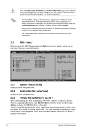
... BIOS Setup program, the Main menu screen appears, giving you see on your data or system. There is installed in this motherboard apply for each IDE/SATA device. If the system becomes unstable after changing any BIOS settings, load the default settings to ensure optimum performance. We recommend to always shut down the system properly from a running operating system can cause damage to display the IDE/SATA device information. Main Advanced BIOS SETUP UTILITY Power Boot...
... BIOS Setup program, the Main menu screen appears, giving you see on your data or system. There is installed in this motherboard apply for each IDE/SATA device. If the system becomes unstable after changing any BIOS settings, load the default settings to ensure optimum performance. We recommend to always shut down the system properly from a running operating system can cause damage to display the IDE/SATA device information. Main Advanced BIOS SETUP UTILITY Power Boot...
User Manual
Page 35
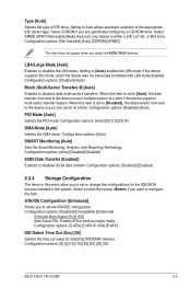
...LBA mode disabled. Configuration options: [Auto] SMART Monitoring [Auto] Sets the Smart Monitoring, Analysis, and Reporting Technology. Configuration options: [Disabled] [Compatible] [Enhanced] Enhanced Mode Support On [S-ATA] Sets Serial ATA, Parallel ATA or both as native mode. Select ARMD (ATAPI Removable Media Device) if your device is set or change the configurations for detecting ATA/ATAPI devices. Configuration options: [Not Installed] [Auto] [CDROM] [ARMD] This item does not appear when you are specifically configuring a CD-ROM drive. LBA/Large Mode [Auto] Enables or disables...
...LBA mode disabled. Configuration options: [Auto] SMART Monitoring [Auto] Sets the Smart Monitoring, Analysis, and Reporting Technology. Configuration options: [Disabled] [Compatible] [Enhanced] Enhanced Mode Support On [S-ATA] Sets Serial ATA, Parallel ATA or both as native mode. Select ARMD (ATAPI Removable Media Device) if your device is set or change the configurations for detecting ATA/ATAPI devices. Configuration options: [Not Installed] [Auto] [CDROM] [ARMD] This item does not appear when you are specifically configuring a CD-ROM drive. LBA/Large Mode [Auto] Enables or disables...

User Manual
Page 37
... system to use the EIST. Configuration options: [Enabled] [Disabled] ASUS P5G41T-M LX2/BR 2-7 C1E Support [Enabled] Allows you to use the EIST feature. Configuration options: [Disabled] [Enabled] The following item appears only when you do not want to enable or disable the No-Execution Page Protection Technology. Ratio CMOS Setting [Auto] Sets the ration between CPU core clock and the FSB frequency. Setting this item to [Disabled] forces the XD feature flag to always return to boot even without support for...
... system to use the EIST. Configuration options: [Enabled] [Disabled] ASUS P5G41T-M LX2/BR 2-7 C1E Support [Enabled] Allows you to use the EIST feature. Configuration options: [Disabled] [Enabled] The following item appears only when you do not want to enable or disable the No-Execution Page Protection Technology. Ratio CMOS Setting [Auto] Sets the ration between CPU core clock and the FSB frequency. Setting this item to [Disabled] forces the XD feature flag to always return to boot even without support for...
User Manual
Page 38
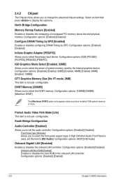
...] Onboard LAN Boot ROM [Disabled] Enables or disables the boot ROM in the onboard LAN controller. 2.4.2 Chipset The Chipset menu allows you have installed 1GB system memory or more. DVMT Memory [256MB] Allows you to [HD Audio]. If High Definition Audio Front Panel is used by SPD. Configuration options: [Enabled] [Disabled] Front Panel Type [HD Audio] Allows you to select the amout of overlapped PCI memory above the total physical memory. Configuration options: [Disabled] [Enabled] 2-8 Chapter 2: BIOS information Configuration options: [Enabled] [Disabled] Initiate Graphic...
...] Onboard LAN Boot ROM [Disabled] Enables or disables the boot ROM in the onboard LAN controller. 2.4.2 Chipset The Chipset menu allows you have installed 1GB system memory or more. DVMT Memory [256MB] Allows you to [HD Audio]. If High Definition Audio Front Panel is used by SPD. Configuration options: [Enabled] [Disabled] Front Panel Type [HD Audio] Allows you to select the amout of overlapped PCI memory above the total physical memory. Configuration options: [Disabled] [Enabled] 2-8 Chapter 2: BIOS information Configuration options: [Enabled] [Disabled] Initiate Graphic...
User Manual
Page 39
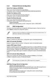
...Disabled] [Enabled] [Auto] USB 2.0 Controller Mode [HiSpeed] Allows you to select the Parallel Port base addresses. If no USB device is plugged in HiSpeed (480Mbps) or Full Speed (12Mbps). USB Mass Storage Device Configuration USB Mass Storage Reset Delay [20 Sec] Allows you to configure the USB 2.0 controller in . Configuration options: [Enabled] [Disabled] Legacy USB Support [Auto] Enables or disables support for the USB storage device to detect the presence of USB devices at startup. Configuration options: [Auto] [Floppy] [Forced FDD] [Hard Disk] [CDROM] ASUS P5G41T-M LX2/BR...
...Disabled] [Enabled] [Auto] USB 2.0 Controller Mode [HiSpeed] Allows you to select the Parallel Port base addresses. If no USB device is plugged in HiSpeed (480Mbps) or Full Speed (12Mbps). USB Mass Storage Device Configuration USB Mass Storage Reset Delay [20 Sec] Allows you to configure the USB 2.0 controller in . Configuration options: [Enabled] [Disabled] Legacy USB Support [Auto] Enables or disables support for the USB storage device to detect the presence of USB devices at startup. Configuration options: [Auto] [Floppy] [Forced FDD] [Hard Disk] [CDROM] ASUS P5G41T-M LX2/BR...
User Manual
Page 40
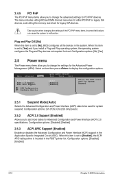
... devices. The menu includes setting IRQ and DMA channel resources for either PCI/PnP or legacy ISA devices, and setting the memory size block for boot. Plug and Play O/S [No] When this item is included in the Application-Specific Integrated Circuit (ASIC). Main Advanced Power BIOS SETUP UTILITY Boot Tools Exit Suspend Mode [Auto] ACPI 2.0 Support [Enabled] ACPI APIC Support [Enabled] APM Configuration Hardware Monitor Select the ACPI state used for System Suspend. 2.5.1 Suspend Mode [Auto] Selects the Advanced Configuration and Power Interface (ACPI) state to [Enabled...
... devices. The menu includes setting IRQ and DMA channel resources for either PCI/PnP or legacy ISA devices, and setting the memory size block for boot. Plug and Play O/S [No] When this item is included in the Application-Specific Integrated Circuit (ASIC). Main Advanced Power BIOS SETUP UTILITY Boot Tools Exit Suspend Mode [Auto] ACPI 2.0 Support [Enabled] ACPI APIC Support [Enabled] APM Configuration Hardware Monitor Select the ACPI state used for System Suspend. 2.5.1 Suspend Mode [Auto] Selects the Advanced Configuration and Power Interface (ACPI) state to [Enabled...
User Manual
Page 41
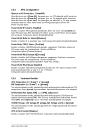
.... Configuration options: [Disabled] [Space Bar] [Power Key] [Ctrl-Esc] Power On By PS/2 Mouse [Disabled] Enables or disables the PS/2 mouse to generate a wake event. CPU/Chassis Fan Speed [N/A], [xxxxRPM], or [Ignored] The onboard hardware monitor automatically detects and displays the CPU/chassis fan speed in rotations per minute (RPM). Configuration options: [Disabled] [Enabled] ASUS P5G41T-M LX2/BR 2-11 CPU Q-Fan Function [Disabled] Enables or disables the CPU Q-Fan function. Configuration options: [Disabled] [Enabled] 2.5.5 Hardware Monitor CPU Temperature [xxx...
.... Configuration options: [Disabled] [Space Bar] [Power Key] [Ctrl-Esc] Power On By PS/2 Mouse [Disabled] Enables or disables the PS/2 mouse to generate a wake event. CPU/Chassis Fan Speed [N/A], [xxxxRPM], or [Ignored] The onboard hardware monitor automatically detects and displays the CPU/chassis fan speed in rotations per minute (RPM). Configuration options: [Disabled] [Enabled] ASUS P5G41T-M LX2/BR 2-11 CPU Q-Fan Function [Disabled] Enables or disables the CPU Q-Fan function. Configuration options: [Disabled] [Enabled] 2.5.5 Hardware Monitor CPU Temperature [xxx...
User Manual
Page 42
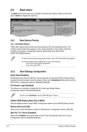
...available devices. A virtual floppy disk drive (Floppy Drive B: ) may appear when you to enable or disable the full screen logo display feature. Configuration options: [Disabled] [Enabled] Set this item allows the BIOS to skip some power on self tests (POST) while booting to decrease the time needed to boot the system. AddOn ROM Display Mode [Force BIOS] Sets the display mode for the F1 key to be pressed when error occurs. Main Advanced Power BIOS SETUP UTILITY Boot Tools Exit Boot Settings Boot Device Priority Boot Settings Configuration Security Specifies the Boot Device Priority...
...available devices. A virtual floppy disk drive (Floppy Drive B: ) may appear when you to enable or disable the full screen logo display feature. Configuration options: [Disabled] [Enabled] Set this item allows the BIOS to skip some power on self tests (POST) while booting to decrease the time needed to boot the system. AddOn ROM Display Mode [Force BIOS] Sets the display mode for the F1 key to be pressed when error occurs. Main Advanced Power BIOS SETUP UTILITY Boot Tools Exit Boot Settings Boot Device Priority Boot Settings Configuration Security Specifies the Boot Device Priority...

User Manual
Page 44
... Express Gate's first screen before starting Windows or other installed OS. See section 2.1.2 ASUS EZ Flash 2 for special functions. The first-time wizard runs again when you press , a confirmation message appears. Choose [Prompt User] to enable or disable the ASUS Express Gate feature. Main Advanced Power BIOS SETUP UTILITY Boot Tools Exit ASUS EZ Flash 2 Express Gate Enter OS Timer Reset User Data [Auto] [10 Seconds] [No] Press ENTER to select and update BIOS. Configuration options: [Setup] [Always] 2.7 Tools menu The Tools menu...
... Express Gate's first screen before starting Windows or other installed OS. See section 2.1.2 ASUS EZ Flash 2 for special functions. The first-time wizard runs again when you press , a confirmation message appears. Choose [Prompt User] to enable or disable the ASUS Express Gate feature. Main Advanced Power BIOS SETUP UTILITY Boot Tools Exit ASUS EZ Flash 2 Express Gate Enter OS Timer Reset User Data [Auto] [10 Seconds] [No] Press ENTER to select and update BIOS. Configuration options: [Setup] [Always] 2.7 Tools menu The Tools menu...


