

User Manual
Page 1
Motherboard P5G41T-M LX2/BR
Motherboard P5G41T-M LX2/BR
User Manual
Page 3
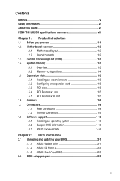
Contents Notices...v Safety information vi About this guide vi P5G41T-M LX2/BR specifications summary viii Chapter 1: Product introduction 1.1 Before you proceed 1-1 1.2 Motherboard overview 1-2 1.2.1 Motherboard layout 1-2 1.2.2 Layout ...Internal connectors 1-9 1.8 Software support 1-15 1.8.1 Installing an operating system 1-15 1.8.2 Support DVD information 1-15 1.8.3 ASUS Express Gate 1-16 Chapter 2: BIOS information 2.1 Managing and updating your BIOS 2-1 2.1.1 ASUS Update utility 2-1 2.1.2 ASUS EZ Flash 2 2-2 2.1.3 ASUS CrashFree BIOS 2-3 2.2 BIOS setup program 2-3 iii
Contents Notices...v Safety information vi About this guide vi P5G41T-M LX2/BR specifications summary viii Chapter 1: Product introduction 1.1 Before you proceed 1-1 1.2 Motherboard overview 1-2 1.2.1 Motherboard layout 1-2 1.2.2 Layout ...Internal connectors 1-9 1.8 Software support 1-15 1.8.1 Installing an operating system 1-15 1.8.2 Support DVD information 1-15 1.8.3 ASUS Express Gate 1-16 Chapter 2: BIOS information 2.1 Managing and updating your BIOS 2-1 2.1.1 ASUS Update utility 2-1 2.1.2 ASUS EZ Flash 2 2-2 2.1.3 ASUS CrashFree BIOS 2-3 2.2 BIOS setup program 2-3 iii
User Manual
Page 8
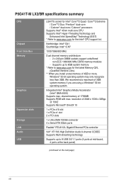
...back panel) (continued on the next page) viii Integrated Intel® Graphics Media Accelerator (Intel® GMA 4500) Supports max. P5G41T-M LX2/BR specifications summary CPU Chipset Front Side Bus Memory Graphics Expansion slots Storage LAN Audio USB LGA775 socket for Intel® Core™2 Quad...® 45nm multi-core CPU Supports Intel® Hyper-Threading Technology and Enhanced Intel SpeedStep® Technology (EIST) * Refer to www.asus.com for the latest Memory QVL (Qualified Vendors Lists). ** When you are using a Windows® 32-bit operating system. shared memory...
...back panel) (continued on the next page) viii Integrated Intel® Graphics Media Accelerator (Intel® GMA 4500) Supports max. P5G41T-M LX2/BR specifications summary CPU Chipset Front Side Bus Memory Graphics Expansion slots Storage LAN Audio USB LGA775 socket for Intel® Core™2 Quad...® 45nm multi-core CPU Supports Intel® Hyper-Threading Technology and Enhanced Intel SpeedStep® Technology (EIST) * Refer to www.asus.com for the latest Memory QVL (Qualified Vendors Lists). ** When you are using a Windows® 32-bit operating system. shared memory...
User Manual
Page 9
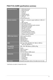
ix P5G41T-M LX2/BR specifications summary Back panel I/O ports Internal connectors ASUS unique features BIOS Manageability Support DVD Accessories Form factor 1 x PS/2 keyboard port 1 x PS/2 mouse port 1 x COM port 1 x VGA port 1 x LAN (RJ-45) port 4 x USB 2.0/1.1 ... 1 x CPU fan connector 1 x Chassis fan connector 1 x 24-pin EATX power connector 1 x 4-pin ATX 12V power connector 1 x Chassis intrusion connector ASUS CrashFree BIOS 3 ASUS Q-Fan ASUS EZ Flash 2 ASUS MyLogo 2 ASUS Express Gate 8Mb Flash ROM, AMI BIOS, PnP, DMI 2.0, WfM 2.0, ACPI 2.0a, SM BIOS 2.5 WOL, PXE, PME Wake up, WOR by Ring...
ix P5G41T-M LX2/BR specifications summary Back panel I/O ports Internal connectors ASUS unique features BIOS Manageability Support DVD Accessories Form factor 1 x PS/2 keyboard port 1 x PS/2 mouse port 1 x COM port 1 x VGA port 1 x LAN (RJ-45) port 4 x USB 2.0/1.1 ... 1 x CPU fan connector 1 x Chassis fan connector 1 x 24-pin EATX power connector 1 x 4-pin ATX 12V power connector 1 x Chassis intrusion connector ASUS CrashFree BIOS 3 ASUS Q-Fan ASUS EZ Flash 2 ASUS MyLogo 2 ASUS Express Gate 8Mb Flash ROM, AMI BIOS, PnP, DMI 2.0, WfM 2.0, ACPI 2.0a, SM BIOS 2.5 WOL, PXE, PME Wake up, WOR by Ring...

User Manual
Page 10
... the power supply case, to avoid damaging them due to static electricity. • Hold components by the edges to page ix for buying an ASUS® P5G41T-M LX2/BR motherboard! Failure to do so may cause severe damage to indicate that the system is ON, in sleep mode, or in the bag that came... comes with a standby power LED that lights up to the motherboard, peripherals, or components. Chapter 1 Product introduction Thank you for the list of accessories. SB_PWR P5G41T-M LX2/BR ON OFF Standby Power Powered Off P5G41T-M LX2/BR Onboard power LED 1-1 ASUS P5G41T-M LX2/BR
... the power supply case, to avoid damaging them due to static electricity. • Hold components by the edges to page ix for buying an ASUS® P5G41T-M LX2/BR motherboard! Failure to do so may cause severe damage to indicate that the system is ON, in sleep mode, or in the bag that came... comes with a standby power LED that lights up to the motherboard, peripherals, or components. Chapter 1 Product introduction Thank you for the list of accessories. SB_PWR P5G41T-M LX2/BR ON OFF Standby Power Powered Off P5G41T-M LX2/BR Onboard power LED 1-1 ASUS P5G41T-M LX2/BR

User Manual
Page 11
... CPU_FAN USB34 USBPW1-4 LAN1_USB12 RTL 8112L AUDIO ICS 9LPRS441 Intel® G41 PCIEX1_1 Lithium Cell CMOS Power PRI_IDE 7 2 24.4cm(9.6in) EATXPWR Super PCIEX16 I/O 16 P5G41T-M LX2/BR SATA4 SATA3 8Mb PCI1 Intel® SATA2 BIOS SATA1 ICH7 PCI2 8 VIA VT1705 CD SB_PWR USBPW5-8 USB56 USB78 CLRTC AAFP CHASSIS F_PANEL 15 14 4 13...
... CPU_FAN USB34 USBPW1-4 LAN1_USB12 RTL 8112L AUDIO ICS 9LPRS441 Intel® G41 PCIEX1_1 Lithium Cell CMOS Power PRI_IDE 7 2 24.4cm(9.6in) EATXPWR Super PCIEX16 I/O 16 P5G41T-M LX2/BR SATA4 SATA3 8Mb PCI1 Intel® SATA2 BIOS SATA1 ICH7 PCI2 8 VIA VT1705 CD SB_PWR USBPW5-8 USB56 USB78 CLRTC AAFP CHASSIS F_PANEL 15 14 4 13...
User Manual
Page 12
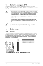
...if you see any damage to the PnP cap/socket contacts/motherboard components. 1.3 Central Processing Unit (CPU) This motherboard comes with less power consumption. ASUS will shoulder the cost of the motherboard, ensure that the PnP cap is shipment/transit-related. • Keep the cap after installing the motherboard. The...resulting from incorrect CPU installation/removal, or misplacement/loss/incorrect removal of the DDR3 DIMM sockets: DIMM_A1 DIMM_B1 Channel Channel A Channel B Sockets DIMM_A1 DIMM_B1 P5G41T-M LX2/BR P5G41T-M LX2/BR 240-pin DDR3 DIMM sockets 1-3 ASUS P5G41T-M LX2/BR
...if you see any damage to the PnP cap/socket contacts/motherboard components. 1.3 Central Processing Unit (CPU) This motherboard comes with less power consumption. ASUS will shoulder the cost of the motherboard, ensure that the PnP cap is shipment/transit-related. • Keep the cap after installing the motherboard. The...resulting from incorrect CPU installation/removal, or misplacement/loss/incorrect removal of the DDR3 DIMM sockets: DIMM_A1 DIMM_B1 Channel Channel A Channel B Sockets DIMM_A1 DIMM_B1 P5G41T-M LX2/BR P5G41T-M LX2/BR 240-pin DDR3 DIMM sockets 1-3 ASUS P5G41T-M LX2/BR
User Manual
Page 13
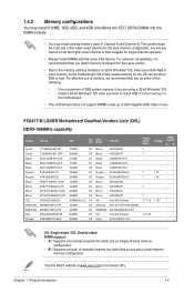
Visit the ASUS website at www.asus.com for the dual-channel configuration. Any excess memory from the same vendor. • Due to install 4GB or more memory on the motherboard. • ... install 4GB or more memory on the motherboard, the actual usable memory for single-channel operation. • Always install DIMMs with the same CAS latency. P5G41T-M LX2/BR Motherboard Qualified Vendors Lists (QVL) DDR3-1066MHz capability Vendor Part No. 1.4.2 Memory configurations You may install 512MB, 1GB, 2GB, and 4GB unbuffered non‑ECC...
Visit the ASUS website at www.asus.com for the dual-channel configuration. Any excess memory from the same vendor. • Due to install 4GB or more memory on the motherboard. • ... install 4GB or more memory on the motherboard, the actual usable memory for single-channel operation. • Always install DIMMs with the same CAS latency. P5G41T-M LX2/BR Motherboard Qualified Vendors Lists (QVL) DDR3-1066MHz capability Vendor Part No. 1.4.2 Memory configurations You may install 512MB, 1GB, 2GB, and 4GB unbuffered non‑ECC...
User Manual
Page 14
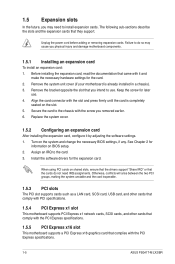
... specifications. 1.5.4 PCI Express x1 slot This motherboard supports PCI Express x1 network cards, SCSI cards, and other cards that comply with the PCI Express specifications. 1-5 ASUS P5G41T-M LX2/BR 1.5 Expansion slots In the future, you may cause you physical injury and damage motherboard components. 1.5.1 Installing an expansion card To install an expansion card: 1. Secure...
... specifications. 1.5.4 PCI Express x1 slot This motherboard supports PCI Express x1 network cards, SCSI cards, and other cards that comply with the PCI Express specifications. 1-5 ASUS P5G41T-M LX2/BR 1.5 Expansion slots In the future, you may cause you physical injury and damage motherboard components. 1.5.1 Installing an expansion card To install an expansion card: 1. Secure...
User Manual
Page 15
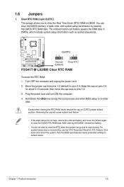
.... Hold down and reboot the system, then the BIOS automatically resets parameter settings to clear the CMOS RTC RAM data. CLRTC 12 23 P5G41T-M LX2/BR Normal (Default) Clear RTC P5G41T-M LX2/BR Clear RTC RAM To erase the RTC RAM: 1. Keep the cap on CLRTC jumper default position. Except when clearing the RTC RAM, never...
.... Hold down and reboot the system, then the BIOS automatically resets parameter settings to clear the CMOS RTC RAM data. CLRTC 12 23 P5G41T-M LX2/BR Normal (Default) Clear RTC P5G41T-M LX2/BR Clear RTC RAM To erase the RTC RAM: 1. Keep the cap on CLRTC jumper default position. Except when clearing the RTC RAM, never...
User Manual
Page 16
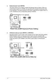
... mode (CPU stopped, DRAM refreshed, system running in the BIOS. USBPW1-4 12 23 +5V +5VSB (Default) USBPW5-8 P5G41T-M LX2/BR 12 23 +5V +5VSB (Default) P5G41T-M LX2/BR USB Device Wake-Up 1-7 ASUS P5G41T-M LX2/BR KBPWR 12 23 +5V +5VSB (Default) P5G41T-M LX2/BR P5G41T-M LX2/BR Keyboard Power Setting 3. 2. Keyboard power (3-pin KBPWR) This jumper allows you to CPU, DRAM in slow refresh, power...
... mode (CPU stopped, DRAM refreshed, system running in the BIOS. USBPW1-4 12 23 +5V +5VSB (Default) USBPW5-8 P5G41T-M LX2/BR 12 23 +5V +5VSB (Default) P5G41T-M LX2/BR USB Device Wake-Up 1-7 ASUS P5G41T-M LX2/BR KBPWR 12 23 +5V +5VSB (Default) P5G41T-M LX2/BR P5G41T-M LX2/BR Keyboard Power Setting 3. 2. Keyboard power (3-pin KBPWR) This jumper allows you to CPU, DRAM in slow refresh, power...
User Manual
Page 18
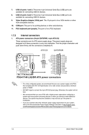
... Video Graphics Adapter (VGA) port. This 15-pin port is for details. 1-9 ASUS P5G41T-M LX2/BR The power supply plugs are designed to install additional devices. 7. COM port. ATX12V EATXPWR +12V DC +12V DC P5G41T-M LX2/BR GND GND +3 Volts +12 Volts +12 Volts +5V Standby Power OK PIN 1...+5 Volts GND +3 Volts +3 Volts PIN 1 GND +5 Volts +5 Volts +5 Volts -5 Volts GND GND GND PSON# GND -12 Volts +3 Volts P5G41T-M LX2/BR ATX power connectors • For a fully configured system, we recommend that you use a power supply unit (PSU) that you use a PSU with a...
... Video Graphics Adapter (VGA) port. This 15-pin port is for details. 1-9 ASUS P5G41T-M LX2/BR The power supply plugs are designed to install additional devices. 7. COM port. ATX12V EATXPWR +12V DC +12V DC P5G41T-M LX2/BR GND GND +3 Volts +12 Volts +12 Volts +5V Standby Power OK PIN 1...+5 Volts GND +3 Volts +3 Volts PIN 1 GND +5 Volts +5 Volts +5 Volts -5 Volts GND GND GND PSON# GND -12 Volts +3 Volts P5G41T-M LX2/BR ATX power connectors • For a fully configured system, we recommend that you use a power supply unit (PSU) that you use a PSU with a...
User Manual
Page 19
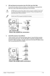
...RSATA_RXN3 RSATA_RXP3 GND RSATA_TXN3 RSATA_TXP3 GND SATA3 GND RSATA_RXN2 RSATA_RXP2 GND RSATA_TXN2 RSATA_TXP2 GND GND RSATA_RXN1 RSATA_RXP1 GND RSATA_TXN1 RSATA_TXP1 GND P5G41T-M LX2/BR SATA2 SATA1 P5G41T-M LX2/BR SATA connectors Chapter 1: Product introduction 1-10 2. CPU and Chassis fan connectors (4-pin CPU_FAN, 3-pin CHA_FAN) Connect ... the ASUS Q-Fan feature. DO NOT forget to connect the fan cables to the fan connectors on the fan connectors! These are for the Serial ATA signal cables for Serial ATA 3Gb/s hard disk drives and optical disk drives. P5G41T-M LX2/BR CHA_FAN ...
...RSATA_RXN3 RSATA_RXP3 GND RSATA_TXN3 RSATA_TXP3 GND SATA3 GND RSATA_RXN2 RSATA_RXP2 GND RSATA_TXN2 RSATA_TXP2 GND GND RSATA_RXN1 RSATA_RXP1 GND RSATA_TXN1 RSATA_TXP1 GND P5G41T-M LX2/BR SATA2 SATA1 P5G41T-M LX2/BR SATA connectors Chapter 1: Product introduction 1-10 2. CPU and Chassis fan connectors (4-pin CPU_FAN, 3-pin CHA_FAN) Connect ... the ASUS Q-Fan feature. DO NOT forget to connect the fan cables to the fan connectors on the fan connectors! These are for the Serial ATA signal cables for Serial ATA 3Gb/s hard disk drives and optical disk drives. P5G41T-M LX2/BR CHA_FAN ...
User Manual
Page 20
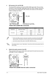
IDE connector (40-1 pin PRI_IDE) The onboard IDE connector is for Ultra DMA 100/66 IDE devices. P5G41T-M LX2/BR IDE connector Single device Two devices Drive jumper setting Cable-Select or Master Cable-Select Master Slave Mode of the following ...Black Black Gray Black or gray • Pin 20 on the Ultra DMA cable connector. PIN1 PRI_IDE P5G41T-M LX2/BR NOTE:Orient the red markings on each Ultra DMA 100/66 signal cable: blue, black, and gray. CD Right Audio Channel GND GND Left Audio Channel P5G41T-M LX2/BR P5G41T-M LX2/BR Internal audio connector 1-11 ASUS P5G41T-M LX2/BR
IDE connector (40-1 pin PRI_IDE) The onboard IDE connector is for Ultra DMA 100/66 IDE devices. P5G41T-M LX2/BR IDE connector Single device Two devices Drive jumper setting Cable-Select or Master Cable-Select Master Slave Mode of the following ...Black Black Gray Black or gray • Pin 20 on the Ultra DMA cable connector. PIN1 PRI_IDE P5G41T-M LX2/BR NOTE:Orient the red markings on each Ultra DMA 100/66 signal cable: blue, black, and gray. CD Right Audio Channel GND GND Left Audio Channel P5G41T-M LX2/BR P5G41T-M LX2/BR Internal audio connector 1-11 ASUS P5G41T-M LX2/BR

User Manual
Page 21
... for USB 2.0 ports. Doing so will damage the motherboard! USB+5V USB_P8USB_P8+ GND NC USB+5V USB_P6USB_P6+ GND NC P5G41T-M LX2/BR USB56 PIN 1 USB78 PIN 1 USB+5V USB_P7USB_P7+ GND USB+5V USB_P5USB_P5+ GND P5G41T-M LX2/BR USB2.0 connectors Never connect a 1394 cable to 480Mbps connection speed. 6. The USB 2.0 module is purchased separately. These USB connectors...
... for USB 2.0 ports. Doing so will damage the motherboard! USB+5V USB_P8USB_P8+ GND NC USB+5V USB_P6USB_P6+ GND NC P5G41T-M LX2/BR USB56 PIN 1 USB78 PIN 1 USB+5V USB_P7USB_P7+ GND USB+5V USB_P5USB_P5+ GND P5G41T-M LX2/BR USB2.0 connectors Never connect a 1394 cable to 480Mbps connection speed. 6. The USB 2.0 module is purchased separately. These USB connectors...
User Manual
Page 22
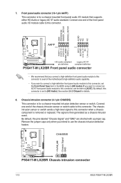
...1 PIN 1 MIC2 MICPWR Line out_R NC Line out_L PORT1 L PORT1 R PORT2 R SENSE_SEND PORT2 L P5G41T-M LX2/BR HD-audio-compliant Legacy AC'97 pin definition compliant definition P5G41T-M LX2/BR Front panel audio connector • We recommend that supports either HD Audio or legacy AC`97 audio standard... pins labeled "Chassis Signal" and "GND" are shorted with a jumper cap. CHASSIS +5VSB_MB Chassis Signal GND P5G41T-M LX2/BR P5G41T-M LX2/BR Chassis intrusion connector 1-13 ASUS P5G41T-M LX2/BR See section 2.4.2 Chipset for a chassis-mounted intrusion detection sensor or switch.
...1 PIN 1 MIC2 MICPWR Line out_R NC Line out_L PORT1 L PORT1 R PORT2 R SENSE_SEND PORT2 L P5G41T-M LX2/BR HD-audio-compliant Legacy AC'97 pin definition compliant definition P5G41T-M LX2/BR Front panel audio connector • We recommend that supports either HD Audio or legacy AC`97 audio standard... pins labeled "Chassis Signal" and "GND" are shorted with a jumper cap. CHASSIS +5VSB_MB Chassis Signal GND P5G41T-M LX2/BR P5G41T-M LX2/BR Chassis intrusion connector 1-13 ASUS P5G41T-M LX2/BR See section 2.4.2 Chipset for a chassis-mounted intrusion detection sensor or switch.

User Manual
Page 23
PLED+ PLEDPWR GND IDE_LED+ IDE_LED- F_PANEL PWR LED PWR BTN PIN 1 P5G41T-M LX2/BR HD LED RESET P5G41T-M LX2/BR System panel connector • System power LED (2-pin PLED) This 2-pin connector is for system reboot without turning off button (2-pin PWRBTN) This 2-pin connector ...
PLED+ PLEDPWR GND IDE_LED+ IDE_LED- F_PANEL PWR LED PWR BTN PIN 1 P5G41T-M LX2/BR HD LED RESET P5G41T-M LX2/BR System panel connector • System power LED (2-pin PLED) This 2-pin connector is for system reboot without turning off button (2-pin PWRBTN) This 2-pin connector ...
User Manual
Page 24
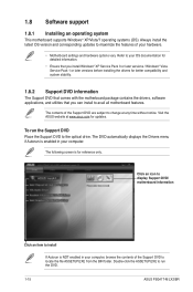
... your hardware. • Motherboard settings and hardware options vary. Double-click the ASSETUP.EXE to avail all motherboard features. Visit the ASUS website at any time without notice. The contents of the Support DVD are subject to maximize the features of the Support DVD to ...screen is enabled in your computer. Always install the latest OS version and corresponding updates to change at www.asus.com for reference only. To run the DVD. 1-15 ASUS P5G41T-M LX2/BR Click an icon to display Support DVD/ motherboard information Click an item to install If Autorun is NOT ...
... your hardware. • Motherboard settings and hardware options vary. Double-click the ASSETUP.EXE to avail all motherboard features. Visit the ASUS website at any time without notice. The contents of the Support DVD are subject to maximize the features of the Support DVD to ...screen is enabled in your computer. Always install the latest OS version and corresponding updates to change at www.asus.com for reference only. To run the DVD. 1-15 ASUS P5G41T-M LX2/BR Click an icon to display Support DVD/ motherboard information Click an item to install If Autorun is NOT ...
User Manual
Page 26
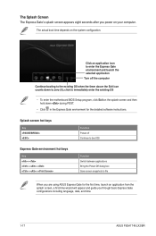
click to file When you are using ASUS Express Gate for the detailed software instructions. The actual boot time depends on the splash screen and then hold down to zero (0); Splash screen hot ... configuration. The Splash Screen The Express Gate's splash screen appears eight seconds after you through basic Express Gate configurations including language, date, and time. 1-17 ASUS P5G41T-M LX2/BR
click to file When you are using ASUS Express Gate for the detailed software instructions. The actual boot time depends on the splash screen and then hold down to zero (0); Splash screen hot ... configuration. The Splash Screen The Express Gate's splash screen appears eight seconds after you through basic Express Gate configurations including language, date, and time. 1-17 ASUS P5G41T-M LX2/BR
User Manual
Page 28
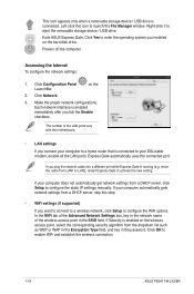
.... If your computer automatically gets network settings from a DHCP server, click Setup to eject the removable storage device / USB drive. If Security is running (e.g. Exits ASUS Express Gate. Click Yes to activate the new setting. If you tick the Enable checkbox. move the cable from the dropdown list such as WEP... step. • WiFi settings (if supported) If you want to connect to a wireless network, click Setup to enable WiFi and establish the wireless connection. 1-19 ASUS P5G41T-M LX2/BR
.... If your computer automatically gets network settings from a DHCP server, click Setup to eject the removable storage device / USB drive. If Security is running (e.g. Exits ASUS Express Gate. Click Yes to activate the new setting. If you tick the Enable checkbox. move the cable from the dropdown list such as WEP... step. • WiFi settings (if supported) If you want to connect to a wireless network, click Setup to enable WiFi and establish the wireless connection. 1-19 ASUS P5G41T-M LX2/BR


