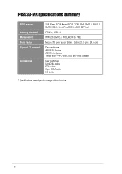
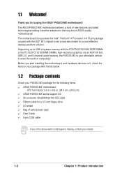
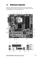
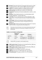
Motherboard DIY Troubleshooting Guide
Page 18
® P4S533-MX P4S533-MX Onboard LED SB_PWR1 ON Standby Power OFF Powered Off 1-8
Motherboard DIY Troubleshooting Guide
Page 26
FLOPPY1 ® P4S533-MX PIN 1 NOTE: Orient the red markings on the floppy ribbon cable to PIN 1. P4S533-MX Floppy Disk Drive Connector SEC_IDE1 PRI_IDE1 1-16 ® P4S533-MX P4S533-MX IDE Connectors PIN 1 PIN 1
Motherboard DIY Troubleshooting Guide
Page 27
COM1 PIN 1 ® P4S533-MX P4S533-MX COM1 Connector ATXPWR1 +5.0VDC +5.0VDC -5.0VDC COM COM COM PS_ON# COM -12.0VDC +3.3VDC +12.0VDC +5VSB PWR_OK COM +5.0VDC COM +5.0VDC COM +3.3VDC +3.3VDC ® P4S533-MX ATX12V1 +12V DC P4S533-MX ATX Power Connectors COM +12V DC COM 1-17
Motherboard DIY Troubleshooting Guide
Page 28
CPU_FAN1 GND +12V Rotation ® P4S533-MX GND +12V Rotation CHA_FAN1 P4S533-MX 12-Volt Cooling Fan Power +5V J1B2 J1CY GND GND J1CX J1B1 +5V MIDI_IN J2B2 J2CY MIDI_OUT J2CX J2B1 +5V ® P4S533-MX P4S533-MX Game Connector GAME1 1-18
Motherboard DIY Troubleshooting Guide
Page 30
® P4S533-MX CD1 (Black) AUX1 (White) Left Audio Channel Ground Ground Right Audio Channel P4S533-MX Internal Audio Connectors MODEM_IN AC97_SYNC AC97_SDIN1 GND AC97_BITCLK ® P4S533-MX P4S533-MX MDC Header MDC GND +3VSB AC97_RST# AC97_SDOUT 1-20
Motherboard DIY Troubleshooting Guide
Page 31
Power LED Speaker Connector +5VSB PLED +5V Ground Ground Speaker PANEL1 IDELED+ IDELED- P4S533-MX System Panel Connectors • • • • • • 1-21 Ground ExtSMI# Ground PWR Ground Reset Ground ® P4S533-MX IDE_LED SMI Lead Reset SW ATX Power Switch* * Requires an ATX power supply.
P4S533-MX User Manual
Page 3
Features Contents Notices v Safety information vi About this guide vii ASUS contact information viii P4S533-MX specifications summary ix Chapter 1: Product introduction 1.1 Welcome 1-2 1.2 Package contents 1-2 1.3 Motherboard components 1-3 1.4 Special Features 1-6 1.5 Motherboard layout 1-7 1.6 Before you proceed ...13 1.11 Jumpers 1-14 1.12 Connectors 1-16 Chapter 2: BIOS information 2.1 Managing and updating your BIOS 2-2 2.1.1 Using ASUS EZ Flash to update the BIOS 2-2 2.1.2 Using AFLASH to update the BIOS 2-4 2.1.3 CrashFree BIOS feature 2-7 2.2 BIOS Setup program 2-8 2.2.1 BIOS...
P4S533-MX User Manual
Page 9
P4S533-MX specifications summary CPU Chipset Front Side Bus (FSB) Memory Expansion slots VGA IDE Audio LAN (optional) Special features Rear panel I/O Internal I/O Socket 478 for Intel... 6-channel CODEC SiS® 962L integrated 10/100 Mbps Fast Ethernet with Realtek external PHY Power Loss Restart Digital audio via an S/PDIF Out inteface ASUS EZ Flash CrashFree BIOS 1 x Parallel port 1 x Video port 1 x PS/2 keyboard port 1 x PS/2 mouse port 4 x USB 2.0/USB 1.1 ports 1 x RJ-45 port (optional) 1 x S/PDIF out Line In...
P4S533-MX User Manual
Page 10
DMI 2.0, WOL/WOR by PME Micro-ATX form factor: 9.6 in x 9.6 in (24.5 cm x 24.5 cm) Device drivers ASUS PC Probe ASUS LiveUpdate Trend Micro™ PC-cillin 2002 anti-virus software User's Manual UltraDMA cable FDD cable 9-pin COM cable I/O shield * Specifications are subject to change without notice. x P4S533-MX specifications summary BIOS features Industry standard Manageability Form Factor Support CD contents Accessories 2Mb Flash ROM, Award BIOS, TCAV, PnP, DMI2.0, WfM2.0, SM BIOS2.3, CrashFree BIOS, ASUS EZ Flash PCI 2.2, USB 2.0 WfM 2.0.
P4S533-MX User Manual
Page 11
It includes brief descriptions of the motherboard components, and illustrations of the P4S533-MX motherboard. Chapter 1 This chapter describes the features of the layout, jumper settings, and connectors. Product introduction
P4S533-MX User Manual
Page 12
...resolution graphics via an AGP 4X slot, USB 2.0, and 6-channel audio features, the P4S533-MX is damaged or missing, contact your retailer. 1-2 Chapter 1: Product introduction Before you for buying the ASUS® P4S533-MX motherboard! Supporting up to 2GB of system memory with the SiS® 651 chipset to... caps User Guide 9-pin COM cable If any of the above items is your P4S533-MX package for the following items. ASUS P4S533-MX motherboard ATX form factor: 9.6 in x 9.6 in (24.5 cm x 24.5 cm) ASUS P4S533-MX series support CD 80-conductor UltraDMA/66/100 IDE cable Ribbon cable for a cost...
P4S533-MX User Manual
Page 13
Refer to facilitate the installation and future upgrades. 1.3 Motherboard components Before you install the motherboard, learn about its major components and available features to the succeeding pages for the component descriptions. 1 2 34 56 16 15 14 13 12 17 18 11 19 27 26 25 24 23 ASUS P4S533-MX motherboard user guide 7 8 9 10 20 21 22 1-3
P4S533-MX User Manual
Page 15
... 2.0 ports 3 and 4. The functions of this jack becomes Front Speaker Out. 22 Microphone jack. This port is for connecting USB 2.0 devices. 24 USB 2.0 ports 1 and 2. ASUS P4S533-MX motherboard user guide 1-5 This green 6-pin connector is for a PS/2 mouse. 18 Parallel port. This Line Out (lime) jack connects a headphone or a speaker. This purple...
P4S533-MX User Manual
Page 16
...during upgrade or invaded by a virus. No more DOS-based flash utility and bootable diskette required. SDRAM and DDRAM Combo (page 1-12) P4S533-MX has two DDR sockets and two SDR sockets that allow up to 3.0+ GHz core frequencies for an optional ROM. CrashFree BIOS (page 2-7) ... restart the system and the BIOS will automatically restore the CPU default setting for functionality and value. Unlike other competing vendors' products, ASUS motherboards now enable users to enjoy this protection feature without the need to open the case to 4.2GB/s data transfer rates. SoundMAX ...
P4S533-MX User Manual
Page 17
... Accelerated Graphics Port (AGP) 01 23 01 23 CR2032 3V Lithium Cell CMOS Power Audio Codec MDC1 CHA_FAN1 SB_PWR1 FP_AUDIO1 PCI Slot 1 ® PCI Slot 2 P4S533-MX PCI Slot 3 FLOPPY1 USB_56 SiS962L MuTLOL Media I/0 USBPWR_56 Super I/O CLRTC1 GAME1 2Mbit Flash BIOS COM1 PANEL1 ASUS P4S533-MX motherboard user guide 1-7
P4S533-MX User Manual
Page 18
Whenever you uninstall any motherboard component. ® P4S533-MX P4S533-MX Onboard LED SB_PWR1 ON Standby Power OFF Powered Off Install only 1.5V AGP cards on this motherboard! 1-8 Chapter 1: Product introduction Before you install or remove ...
P4S533-MX User Manual
Page 19
... physical injury and damage motherboard components. 1.7.1 Placement direction When installing the motherboard, make sure that you install the motherboard, study the configuration of the chassis ASUS P4S533-MX motherboard user guide 1-9 Place this side towards the rear of your chassis to ensure that measures 9.6 inches x 9.6 inches (24.5 cm x 24.5 cm). Failure to do...
P4S533-MX User Manual
Page 21
... secure the CPU. 1.8.2 Installing the CPU Follow these steps to 90°-100° angle, otherwise the CPU does not fit in completely. 90 - 100 3. ASUS P4S533-MX motherboard user guide 1-11 Install a CPU heatsink and fan following the instructions that the socket lever is in place, push down the socket lever to...