P4BP-MX 2.0 user's manual
Page 12
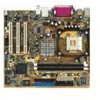
... it , check the items in your package with the list below. 1.2 Package contents Check your motherboard package for the following items. ASUS P4BP-MX 2.0 motherboard ASUS motherboard support CD 1 x IDE cable 1 x Floppy disk cable I/O shield Bag of extra jumper caps User guide If any of the...the motherboard, and hardware devices on it another standout in the world of ASUS quality motherboards! Thank you for an effective desktop platform solution. Supporting up to set a new benchmark for buying the ASUS® P4BP-MX 2.0 motherboard! 1.1 Welcome! Before you ahead in the long line of...
... it , check the items in your package with the list below. 1.2 Package contents Check your motherboard package for the following items. ASUS P4BP-MX 2.0 motherboard ASUS motherboard support CD 1 x IDE cable 1 x Floppy disk cable I/O shield Bag of extra jumper caps User guide If any of the...the motherboard, and hardware devices on it another standout in the world of ASUS quality motherboards! Thank you for an effective desktop platform solution. Supporting up to set a new benchmark for buying the ASUS® P4BP-MX 2.0 motherboard! 1.1 Welcome! Before you ahead in the long line of...

P4BP-MX 2.0 user's manual
Page 13
The motherboard also supports the Intel® Hyper-Threading Technology. supporting up to powerful speaker systems. ASUS P4BP-MX 2.0 motherboard 1-3 USB 2.0 is backward compatible with USB 1.1. 6-Channel Audio solution Onboard is the Realtek® ALC655 AC'97 CODEC. This motherboard supports 533/400 MHz ...
The motherboard also supports the Intel® Hyper-Threading Technology. supporting up to powerful speaker systems. ASUS P4BP-MX 2.0 motherboard 1-3 USB 2.0 is backward compatible with USB 1.1. 6-Channel Audio solution Onboard is the Realtek® ALC655 AC'97 CODEC. This motherboard supports 533/400 MHz ...

P4BP-MX 2.0 user's manual
Page 15
... the ATX power supply is switched off or the power cord is ON, in sleep mode, or in any motherboard component. P4BP-MX 2.0 P4BP-MX 2.0 Onboard LED SB_PWR ON Standby Power OFF Powered Off ASUS P4BP-MX 2.0 motherboard 1-5 Hold components by the edges to the motherboard, peripherals, and/or components. The illustration below shows the location of...
... the ATX power supply is switched off or the power cord is ON, in sleep mode, or in any motherboard component. P4BP-MX 2.0 P4BP-MX 2.0 Onboard LED SB_PWR ON Standby Power OFF Powered Off ASUS P4BP-MX 2.0 motherboard 1-5 Hold components by the edges to the motherboard, peripherals, and/or components. The illustration below shows the location of...
P4BP-MX 2.0 user's manual
Page 17
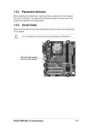
Doing so may damage the motherboard. Do not overtighten the screws! Place this side towards the rear of the chassis as indicated in the image below. 1.5.3 Screw holes Place six (6) screws into the chassis in the correct orientation. 1.5.2 Placement direction When installing the motherboard, make sure that you place it into the holes indicated by circles to secure the motherboard to the chassis. The edge with external ports goes to the rear part of the chassis ASUS P4BP-MX 2.0 motherboard 1-7
Doing so may damage the motherboard. Do not overtighten the screws! Place this side towards the rear of the chassis as indicated in the image below. 1.5.3 Screw holes Place six (6) screws into the chassis in the correct orientation. 1.5.2 Placement direction When installing the motherboard, make sure that you place it into the holes indicated by circles to secure the motherboard to the chassis. The edge with external ports goes to the rear part of the chassis ASUS P4BP-MX 2.0 motherboard 1-7
P4BP-MX 2.0 user's manual
Page 19
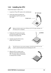
Unlock the socket by pressing the lever sideways, then lift it is in completely. 3. The CPU fits only in place. ASUS P4BP-MX 2.0 motherboard 1-9 Carefully insert the CPU into the socket to install a CPU. 1. When the CPU is locked. Position the CPU above the socket such that the ...
Unlock the socket by pressing the lever sideways, then lift it is in completely. 3. The CPU fits only in place. ASUS P4BP-MX 2.0 motherboard 1-9 Carefully insert the CPU into the socket to install a CPU. 1. When the CPU is locked. Position the CPU above the socket such that the ...
P4BP-MX 2.0 user's manual
Page 21
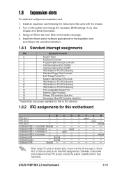
... shared When using PCI cards on the system and change the necessary BIOS settings, if any. used - - - - - Onboard USB 2.0 controller shared Onboard LAN - Onboard Audio - ASUS P4BP-MX 2.0 motherboard 1-11 used - - - - PCI slot 3 shared Onboard USB 1.1 controller 1shared Onboard USB 1.1 controller 2 - - - Install an expansion card following the instructions that the cards do not...
... shared When using PCI cards on the system and change the necessary BIOS settings, if any. used - - - - - Onboard USB 2.0 controller shared Onboard LAN - Onboard Audio - ASUS P4BP-MX 2.0 motherboard 1-11 used - - - - PCI slot 3 shared Onboard USB 1.1 controller 1shared Onboard USB 1.1 controller 2 - - - Install an expansion card following the instructions that the cards do not...
P4BP-MX 2.0 user's manual
Page 23
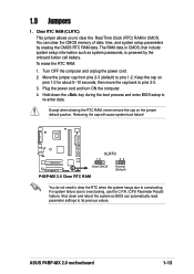
... the boot process and enter BIOS setup to re-enter data. To erase the RTC RAM: 1. Keep the cap on the jumper default position. ASUS P4BP-MX 2.0 motherboard 1-13 Clear RTC RAM (CLRTC) This jumper allows you to its previous values. Hold down and reboot the system so BIOS can clear...seconds, then move the cap back to pins 1-2. The RAM data in CMOS. Removing the cap will cause system boot failure! P4BP-MX 2.0 CLRTC 12 23 Clear CMOS Normal (Default) P4BP-MX 2.0 Clear RTC RAM You do not need to clear the RTC when the system hangs due to overclocking, use the C.P.R. (CPU...
... the boot process and enter BIOS setup to re-enter data. To erase the RTC RAM: 1. Keep the cap on the jumper default position. ASUS P4BP-MX 2.0 motherboard 1-13 Clear RTC RAM (CLRTC) This jumper allows you to its previous values. Hold down and reboot the system so BIOS can clear...seconds, then move the cap back to pins 1-2. The RAM data in CMOS. Removing the cap will cause system boot failure! P4BP-MX 2.0 CLRTC 12 23 Clear CMOS Normal (Default) P4BP-MX 2.0 Clear RTC RAM You do not need to clear the RTC when the system hangs due to overclocking, use the C.P.R. (CPU...
P4BP-MX 2.0 user's manual
Page 25
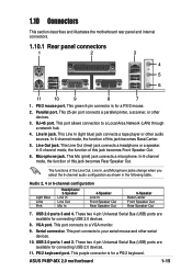
... hub. 4. Serial connector. This green 6-pin connector is for a PS/2 mouse. 2. VGA port. PS/2 keyboard port. This Line Out (lime) jack connects a headphone or a speaker. ASUS P4BP-MX 2.0 motherboard 1-15 Microphone jack. Audio 2, 4 or 6-channel configuration Light Blue Lime Pink Headphone/ 2-Speaker Line In Line Out Mic In 4-Speaker Line In Front Speaker...
... hub. 4. Serial connector. This green 6-pin connector is for a PS/2 mouse. 2. VGA port. PS/2 keyboard port. This Line Out (lime) jack connects a headphone or a speaker. ASUS P4BP-MX 2.0 motherboard 1-15 Microphone jack. Audio 2, 4 or 6-channel configuration Light Blue Lime Pink Headphone/ 2-Speaker Line In Line Out Mic In 4-Speaker Line In Front Speaker...
P4BP-MX 2.0 user's manual
Page 27
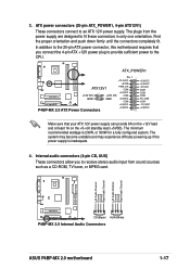
ATX_POWER1 Pin 1 +12.0VDC +5VSB ATX12V1 PWR_OK COM P4BP-MX 2.0 +12V DC GND +12V DC GND +5.0VDC COM +5.0VDC COM +3.3VDC P4BP-MX 2.0 ATX Power Connectors +3.3VDC +5.0VDC +5.0VDC -5.0VDC COM COM COM PS_ON# COM -12.0VDC +3.3VDC Make sure ...12V power supply. 3. Left Audio Channel Ground Ground Right Audio Channel Left Audio Channel Ground Ground Right Audio Channel P4BP-MX 2.0 CD(Black) AUX(White) P4BP-MX 2.0 Internal Audio Connectors ASUS P4BP-MX 2.0 motherboard 1-17 The minimum recommended wattage is inadequate. 4. The system may become unstable and may experience difficulty...
ATX_POWER1 Pin 1 +12.0VDC +5VSB ATX12V1 PWR_OK COM P4BP-MX 2.0 +12V DC GND +12V DC GND +5.0VDC COM +5.0VDC COM +3.3VDC P4BP-MX 2.0 ATX Power Connectors +3.3VDC +5.0VDC +5.0VDC -5.0VDC COM COM COM PS_ON# COM -12.0VDC +3.3VDC Make sure ...12V power supply. 3. Left Audio Channel Ground Ground Right Audio Channel Left Audio Channel Ground Ground Right Audio Channel P4BP-MX 2.0 CD(Black) AUX(White) P4BP-MX 2.0 Internal Audio Connectors ASUS P4BP-MX 2.0 motherboard 1-17 The minimum recommended wattage is inadequate. 4. The system may become unstable and may experience difficulty...
P4BP-MX 2.0 user's manual
Page 29
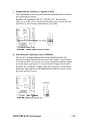
... and the pins LINE OUT_L/BLINE_OUT_L are connecting the front panel audio cable. AGND +5VA BLINE_OUT_R BLINE_OUT_L P4BP-MX 2.0 FP_AUDIO MIC2 MICPWR Line out_R NC Line out_L P4BP-MX 2.0 Front Panel Audio Connector 8. If you remove any chassis component, the sensor triggers and sends a...to use the chassis intrusion detection feature, remove the jumper cap from the pins. +5VSB_MB Chassis Signal GND CHASSIS P4BP-MX 2.0 (Default) P4BP-MX 2.0 Chassis Alarm Lead ASUS P4BP-MX 2.0 motherboard 1-19 Front panel audio connector (10-1 pin FP_AUDIO) This is for the front panel cable that allows...
... and the pins LINE OUT_L/BLINE_OUT_L are connecting the front panel audio cable. AGND +5VA BLINE_OUT_R BLINE_OUT_L P4BP-MX 2.0 FP_AUDIO MIC2 MICPWR Line out_R NC Line out_L P4BP-MX 2.0 Front Panel Audio Connector 8. If you remove any chassis component, the sensor triggers and sends a...to use the chassis intrusion detection feature, remove the jumper cap from the pins. +5VSB_MB Chassis Signal GND CHASSIS P4BP-MX 2.0 (Default) P4BP-MX 2.0 Chassis Alarm Lead ASUS P4BP-MX 2.0 motherboard 1-19 Front panel audio connector (10-1 pin FP_AUDIO) This is for the front panel cable that allows...
P4BP-MX 2.0 user's manual
Page 31
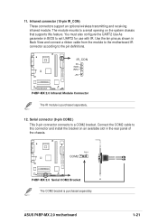
... IR connector according to set UART2 for use with IR. Use the ten pins as shown in BIOS to the pin definitions. PIN 1 COM2 P4BP-MX 2.0 P4BP-MX 2.0 Serial COM2 Bracket The COM2 bracket is purchased separately. 12. Serial connector (9-pin COM2 ) This 9-pin connector connects to this connector and... install the bracket on the system chassis that supports this feature. 11. Connect the COM2 cable to a COM2 bracket. P4BP-MX 2.0 IR_CON PX GND IRRX +5V P4BP-MX 2.0 Infrared Module Connector The IR module is purchased separately. ASUS P4BP-MX 2.0 motherboard 1-21
... IR connector according to set UART2 for use with IR. Use the ten pins as shown in BIOS to the pin definitions. PIN 1 COM2 P4BP-MX 2.0 P4BP-MX 2.0 Serial COM2 Bracket The COM2 bracket is purchased separately. 12. Serial connector (9-pin COM2 ) This 9-pin connector connects to this connector and... install the bracket on the system chassis that supports this feature. 11. Connect the COM2 cable to a COM2 bracket. P4BP-MX 2.0 IR_CON PX GND IRRX +5V P4BP-MX 2.0 Infrared Module Connector The IR module is purchased separately. ASUS P4BP-MX 2.0 motherboard 1-21
P4BP-MX 2.0 user's manual
Page 33
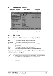
Detailed descriptions of the BIOS parameters are also provided. BIOS information ASUS P4BP-MX 2.0 motherboard 2-1 Chapter 2 This chapter tells how to change system settings through the BIOS Setup menus.
Detailed descriptions of the BIOS parameters are also provided. BIOS information ASUS P4BP-MX 2.0 motherboard 2-1 Chapter 2 This chapter tells how to change system settings through the BIOS Setup menus.
P4BP-MX 2.0 user's manual
Page 35
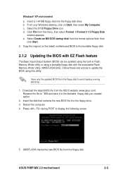
... startup disk from the floppy disk. AWDFLASH checks the new BIOS file from the format options field, then click Start. 2. A Format 3 1/2 Floppy Disk window appears. ASUS P4BP-MX 2.0 motherboard 2-3 Windows® XP environment a. d. Insert the disk that contains the new BIOS file into the floppy disk drive. Save only the updated BIOS file...
... startup disk from the floppy disk. AWDFLASH checks the new BIOS file from the format options field, then click Start. 2. A Format 3 1/2 Floppy Disk window appears. ASUS P4BP-MX 2.0 motherboard 2-3 Windows® XP environment a. d. Insert the disk that contains the new BIOS file into the floppy disk drive. Save only the updated BIOS file...
P4BP-MX 2.0 user's manual
Page 37
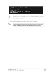
Visit the ASUS website (www.asus.com) to download the latest BIOS file. ASUS P4BP-MX 2.0 motherboard 2-5 Checking for this motherboard. Completed. DO NOT shutdown or reset the system while updating the BIOS! Floppy found! Reading file "p4bp-mx.bin". Start flashing... When the BIOS update process is complete, reboot the system. Doing so may not be the latest BIOS version for floppy... Bad BIOS checksum. Starting BIOS recovery... The recovered BIOS may cause system boot failure! 2.
Visit the ASUS website (www.asus.com) to download the latest BIOS file. ASUS P4BP-MX 2.0 motherboard 2-5 Checking for this motherboard. Completed. DO NOT shutdown or reset the system while updating the BIOS! Floppy found! Reading file "p4bp-mx.bin". Start flashing... When the BIOS update process is complete, reboot the system. Doing so may not be the latest BIOS version for floppy... Bad BIOS checksum. Starting BIOS recovery... The recovered BIOS may cause system boot failure! 2.
P4BP-MX 2.0 user's manual
Page 39
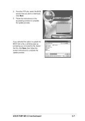
Follow the instructions on the succeeding screens to complete the update process. Select the file, click Save, then follow the screen instructions to complete the update process. Click Next. 5. ASUS P4BP-MX 2.0 motherboard 2-7 From the FTP site, select the BIOS version that you to download. 2. If you selected the option to update the BIOS from a file, a window pops up prompting you wish to locate the file.
Follow the instructions on the succeeding screens to complete the update process. Select the file, click Save, then follow the screen instructions to complete the update process. Click Next. 5. ASUS P4BP-MX 2.0 motherboard 2-7 From the FTP site, select the BIOS version that you to download. 2. If you selected the option to update the BIOS from a file, a window pops up prompting you wish to locate the file.
P4BP-MX 2.0 user's manual
Page 41
... setup screens shown in this chapter are for reference purposes only, and may not exactly match what you see on your screen. • Visit the ASUS website (www.asus.com) to download the latest BIOS information. ASUS P4BP-MX 2.0 motherboard 2-9
... setup screens shown in this chapter are for reference purposes only, and may not exactly match what you see on your screen. • Visit the ASUS website (www.asus.com) to download the latest BIOS information. ASUS P4BP-MX 2.0 motherboard 2-9
P4BP-MX 2.0 user's manual
Page 43
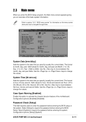
...), Day: (1 to 31), Year: (1999 to change the values. Use the or keys to 2099). Select [Setup] to change the values. Configuration options: [Setup] [System] ASUS P4BP-MX 2.0 motherboard 2-11 Use the or keys to require the password before entering the system. Configuration options: [Enabled] [Disabled] Password Check [Setup] This field requires users...
...), Day: (1 to 31), Year: (1999 to change the values. Use the or keys to 2099). Select [Setup] to change the values. Configuration options: [Setup] [System] ASUS P4BP-MX 2.0 motherboard 2-11 Use the or keys to require the password before entering the system. Configuration options: [Enabled] [Disabled] Password Check [Setup] This field requires users...

P4BP-MX 2.0 user's manual
Page 45
... [Auto] allows automatic detection of cylinder, head, and sector per track for this may also highlight the item, then press to display a pop-up menu. ASUS P4BP-MX 2.0 motherboard 2-13 If no drive is successful, the setup BIOS automatically fills in the value from the drive documentation then press . Select [CHS] for the...
... [Auto] allows automatic detection of cylinder, head, and sector per track for this may also highlight the item, then press to display a pop-up menu. ASUS P4BP-MX 2.0 motherboard 2-13 If no drive is successful, the setup BIOS automatically fills in the value from the drive documentation then press . Select [CHS] for the...

P4BP-MX 2.0 user's manual
Page 47
Configuration options: [1.5] [2] [2.5] [3] Active to configure each item on your own. 2.4 Advanced menu 2.4.1 Advanced Chipset Features DRAM Timing Selectable [By SPD] Sets the DRAM Timing configuration. Configuration options: [7] [6] [5] ASUS P4BP-MX 2.0 motherboard 2-15 Set to manual if you want to Precharge Delay [7] Controls the number of DRAM clocks used for the DRAM parameters. Configuration options: [Manual] [By SPD] CAS Latency Time [1.5] Sets the latency between the DRAM command and the time the data actually become available.
Configuration options: [1.5] [2] [2.5] [3] Active to configure each item on your own. 2.4 Advanced menu 2.4.1 Advanced Chipset Features DRAM Timing Selectable [By SPD] Sets the DRAM Timing configuration. Configuration options: [7] [6] [5] ASUS P4BP-MX 2.0 motherboard 2-15 Set to manual if you want to Precharge Delay [7] Controls the number of DRAM clocks used for the DRAM parameters. Configuration options: [Manual] [By SPD] CAS Latency Time [1.5] Sets the latency between the DRAM command and the time the data actually become available.
P4BP-MX 2.0 user's manual
Page 49
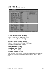
... PIO [Auto] These items allow you to set a PIO (Programmable Input/Output) mode for primary IDE devices. Configuration options: [Auto] [Mode 0] [Mode 1] [Mode 2] [Mode 3] [Mode 4] ASUS P4BP-MX 2.0 motherboard 2-17 Configuration options: [Disabled] [Enabled] On-Chip Primary PCI IDE [Enabled] Disables or enables the On-chip Primary PCI IDE support. 2.4.2 Chip Configuration IDE...
... PIO [Auto] These items allow you to set a PIO (Programmable Input/Output) mode for primary IDE devices. Configuration options: [Auto] [Mode 0] [Mode 1] [Mode 2] [Mode 3] [Mode 4] ASUS P4BP-MX 2.0 motherboard 2-17 Configuration options: [Disabled] [Enabled] On-Chip Primary PCI IDE [Enabled] Disables or enables the On-chip Primary PCI IDE support. 2.4.2 Chip Configuration IDE...


