
Motherboard DIY Troubleshooting Guide
Page 27
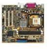
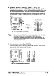
ATX_POWER1 Pin 1 +12.0VDC +5VSB ATX12V1 PWR_OK COM P4BP-MX 2.0 +12V DC GND +12V DC GND +5.0VDC COM +5.0VDC COM +3.3VDC P4BP-MX 2.0 ATX Power Connectors +3.3VDC +5.0VDC +5.0VDC -5.0VDC COM COM COM PS_ON# COM -12.0VDC +3.3VDC Left Audio Channel Ground Ground Right Audio Channel Left Audio Channel Ground Ground Right Audio Channel P4BP-MX 2.0 CD(Black) AUX(White) P4BP-MX 2.0 Internal Audio Connectors 1-17
ATX_POWER1 Pin 1 +12.0VDC +5VSB ATX12V1 PWR_OK COM P4BP-MX 2.0 +12V DC GND +12V DC GND +5.0VDC COM +5.0VDC COM +3.3VDC P4BP-MX 2.0 ATX Power Connectors +3.3VDC +5.0VDC +5.0VDC -5.0VDC COM COM COM PS_ON# COM -12.0VDC +3.3VDC Left Audio Channel Ground Ground Right Audio Channel Left Audio Channel Ground Ground Right Audio Channel P4BP-MX 2.0 CD(Black) AUX(White) P4BP-MX 2.0 Internal Audio Connectors 1-17
P4BP-MX 2.0 user's manual
Page 4
...Managing and updating your BIOS 2-2 2.1.1 Creating a bootable floppy disk 2-2 2.1.2 Updating the BIOS with EZ Flash feature 2-3 2.1.3 Recovering the BIOS with CrashFree BIOS .......... 2-4 2.1.4 ASUS Update 2-6 2.2 BIOS Setup program 2-8 2.2.1 BIOS menu screen 2-9 2.2.2 Menu bar 2-9 2.2.3 Legend bar 2-10 2.2.4 General help 2-10 2.2.5 Sub-menu 2-10 2.2.6 Pop... support 3.1 Install an operating system 3-2 3.2 Support CD information 3-2 3.2.1 Running the support CD 3-2 3.2.2 Drivers menu 3-3 3.2.3 Utilities menu 3-3 3.2.4 ASUS Contact Information 3-4 3.3 Audio configuration 3-5 iv
...Managing and updating your BIOS 2-2 2.1.1 Creating a bootable floppy disk 2-2 2.1.2 Updating the BIOS with EZ Flash feature 2-3 2.1.3 Recovering the BIOS with CrashFree BIOS .......... 2-4 2.1.4 ASUS Update 2-6 2.2 BIOS Setup program 2-8 2.2.1 BIOS menu screen 2-9 2.2.2 Menu bar 2-9 2.2.3 Legend bar 2-10 2.2.4 General help 2-10 2.2.5 Sub-menu 2-10 2.2.6 Pop... support 3.1 Install an operating system 3-2 3.2 Support CD information 3-2 3.2.1 Running the support CD 3-2 3.2.2 Drivers menu 3-3 3.2.3 Utilities menu 3-3 3.2.4 ASUS Contact Information 3-4 3.3 Audio configuration 3-5 iv
P4BP-MX 2.0 user's manual
Page 8
P4BP-MX 2.0 specifications summary CPU Chipset Front System Bus Memory Expansion slots Storage Audio LAN USB Special features Rear Panel I/O Internal I/O connectors ` viii Socket 478 for Intel® Pentium® 4 / Celeron® processors ...® ALC655 6-channel CODEC Supports S/PDIF Out interface Realtek® 8100C integrated 10/100Mbps LAN controller Maximum of six (6) USB 2.0 ports ASUS JumperFree ASUS C.P.R. (CPU Parameter Recall) ASUS CrashFree BIOS ASUS EZ Flash ASUS MyLogo™ Power Loss Restart STR (Suspend-to-RAM) CPU Throttle 1 x Parallel port 1 x Serial port 1 x VGA port 1 ...
P4BP-MX 2.0 specifications summary CPU Chipset Front System Bus Memory Expansion slots Storage Audio LAN USB Special features Rear Panel I/O Internal I/O connectors ` viii Socket 478 for Intel® Pentium® 4 / Celeron® processors ...® ALC655 6-channel CODEC Supports S/PDIF Out interface Realtek® 8100C integrated 10/100Mbps LAN controller Maximum of six (6) USB 2.0 ports ASUS JumperFree ASUS C.P.R. (CPU Parameter Recall) ASUS CrashFree BIOS ASUS EZ Flash ASUS MyLogo™ Power Loss Restart STR (Suspend-to-RAM) CPU Throttle 1 x Parallel port 1 x Serial port 1 x VGA port 1 ...
P4BP-MX 2.0 user's manual
Page 12
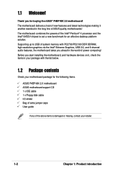
...Product introduction Supporting up to 2GB of system memory with the list below. 1.2 Package contents Check your motherboard package for the following items. ASUS P4BP-MX 2.0 motherboard ASUS motherboard support CD 1 x IDE cable 1 x Floppy disk cable I/O shield Bag of extra jumper caps User guide If any of the...the world of ASUS quality motherboards! The motherboard combines the powers of the above items is damaged or missing, contact your package with PC2700/PC2100 DDR SDRAM, high-resolution graphics via the Intel® Extreme Graphics, USB 2.0, and 6-channel audio features, the ...
...Product introduction Supporting up to 2GB of system memory with the list below. 1.2 Package contents Check your motherboard package for the following items. ASUS P4BP-MX 2.0 motherboard ASUS motherboard support CD 1 x IDE cable 1 x Floppy disk cable I/O shield Bag of extra jumper caps User guide If any of the...the world of ASUS quality motherboards! The motherboard combines the powers of the above items is damaged or missing, contact your package with PC2700/PC2100 DDR SDRAM, high-resolution graphics via the Intel® Extreme Graphics, USB 2.0, and 6-channel audio features, the ...

P4BP-MX 2.0 user's manual
Page 13
.... The motherboard also supports the Intel® Hyper-Threading Technology. USB 2.0 is backward compatible with USB 1.1. 6-Channel Audio solution Onboard is the Realtek® ALC655 AC'97 CODEC. This CODEC provides high-quality 6-channel audio, S/PDIF out support and connector sensing function without having to a fast 480 Mbps on 0.13 or 0.09... for the Intel® Pentium® 4 processor in the 478-pin package with 512/256KB L2 cache on USB 2.0 - supporting up to powerful speaker systems. ASUS P4BP-MX 2.0 motherboard 1-3
.... The motherboard also supports the Intel® Hyper-Threading Technology. USB 2.0 is backward compatible with USB 1.1. 6-Channel Audio solution Onboard is the Realtek® ALC655 AC'97 CODEC. This CODEC provides high-quality 6-channel audio, S/PDIF out support and connector sensing function without having to a fast 480 Mbps on 0.13 or 0.09... for the Intel® Pentium® 4 processor in the 478-pin package with 512/256KB L2 cache on USB 2.0 - supporting up to powerful speaker systems. ASUS P4BP-MX 2.0 motherboard 1-3

P4BP-MX 2.0 user's manual
Page 16
... In Center:Line Out Below:Mic In FP_AUDIO Intel 82845GV Memory Controller Hub 01 23 SEC_IDE PRI_ IDE 3Mbit Firmware Hub RTL8100C PCI1 P4BP-MX 2.0 PCI2 Intel 82801DB ICH4 Audio Codec SPDIF_OUT CD PCI3 CHA_FAN AUX SB_PWR COM2 USBPWR_56 USB56 GAME1 CLRTC BUZZ PLED CHASSIS F_PANEL USBPWR_12 3 2 2 1 +5V (Default) +5VSB KBPWR 2 1 +5V 3 2 +5VSB...
... In Center:Line Out Below:Mic In FP_AUDIO Intel 82845GV Memory Controller Hub 01 23 SEC_IDE PRI_ IDE 3Mbit Firmware Hub RTL8100C PCI1 P4BP-MX 2.0 PCI2 Intel 82801DB ICH4 Audio Codec SPDIF_OUT CD PCI3 CHA_FAN AUX SB_PWR COM2 USBPWR_56 USB56 GAME1 CLRTC BUZZ PLED CHASSIS F_PANEL USBPWR_12 3 2 2 1 +5V (Default) +5VSB KBPWR 2 1 +5V 3 2 +5VSB...
P4BP-MX 2.0 user's manual
Page 21
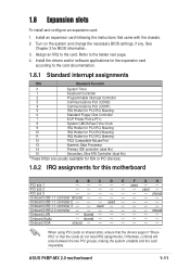
... - Onboard Audio - Onboard VGA shared When using PCI cards on the system and change the necessary BIOS settings, if any. Refer to the card. Turn on shared slots, ensure that the drivers support "Share IRQ" or that came with the chassis. 2. used - - - - 1.8 Expansion slots To install and configure an expansion card: 1. ASUS P4BP-MX...
... - Onboard Audio - Onboard VGA shared When using PCI cards on the system and change the necessary BIOS settings, if any. Refer to the card. Turn on shared slots, ensure that the drivers support "Share IRQ" or that came with the chassis. 2. used - - - - 1.8 Expansion slots To install and configure an expansion card: 1. ASUS P4BP-MX...
P4BP-MX 2.0 user's manual
Page 25
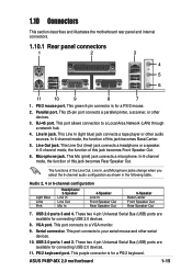
.../Center Front Speaker Out Rear Speaker Out 7. This green 6-pin connector is for a PS/2 mouse. 2. This Mic (pink) jack connects a microphone. ASUS P4BP-MX 2.0 motherboard 1-15 In 6-channel mode, the function of the Line Out, Line In, and Microphone jacks change when you select the 6-channel audio configuration as shown in the following table.
.../Center Front Speaker Out Rear Speaker Out 7. This green 6-pin connector is for a PS/2 mouse. 2. This Mic (pink) jack connects a microphone. ASUS P4BP-MX 2.0 motherboard 1-15 In 6-channel mode, the function of the Line Out, Line In, and Microphone jacks change when you select the 6-channel audio configuration as shown in the following table.
P4BP-MX 2.0 user's manual
Page 27
In addition to the CPU. The minimum recommended wattage is inadequate. 4. Left Audio Channel Ground Ground Right Audio Channel Left Audio Channel Ground Ground Right Audio Channel P4BP-MX 2.0 CD(Black) AUX(White) P4BP-MX 2.0 Internal Audio Connectors ASUS P4BP-MX 2.0 motherboard 1-17 Internal audio connectors (4-pin CD, AUX) These connectors allow you connect the 4-pin ATX +12V power plug to provide sufficient power...
In addition to the CPU. The minimum recommended wattage is inadequate. 4. Left Audio Channel Ground Ground Right Audio Channel Left Audio Channel Ground Ground Right Audio Channel P4BP-MX 2.0 CD(Black) AUX(White) P4BP-MX 2.0 Internal Audio Connectors ASUS P4BP-MX 2.0 motherboard 1-17 Internal audio connectors (4-pin CD, AUX) These connectors allow you connect the 4-pin ATX +12V power plug to provide sufficient power...
P4BP-MX 2.0 user's manual
Page 29
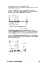
... chassis intrusion detection feature, remove the jumper cap from the pins. +5VSB_MB Chassis Signal GND CHASSIS P4BP-MX 2.0 (Default) P4BP-MX 2.0 Chassis Alarm Lead ASUS P4BP-MX 2.0 motherboard 1-19 7. Remove the caps only when you are shorted with jumper caps. Front panel audio connector (10-1 pin FP_AUDIO) This is for the front panel cable that allows convenient connection...
... chassis intrusion detection feature, remove the jumper cap from the pins. +5VSB_MB Chassis Signal GND CHASSIS P4BP-MX 2.0 (Default) P4BP-MX 2.0 Chassis Alarm Lead ASUS P4BP-MX 2.0 motherboard 1-19 7. Remove the caps only when you are shorted with jumper caps. Front panel audio connector (10-1 pin FP_AUDIO) This is for the front panel cable that allows convenient connection...

P4BP-MX 2.0 user's manual
Page 30
...GAME/MIDI cable to this connector and the other end to the S/PDIF module. +5V SPDIFOUT GND P4BP-MX 2.0 SPDIF_OUT P4BP-MX 2.0 Digital Audio Connector 1-20 Chapter 1: Product introduction Digital Audio connector (6-1 pin SPDIF_OUT) This connector is purchased separately. 10. The GAME/MIDI port on the module ...J1CX J1B1 +5V MIDI_IN J2B2 J2CY MIDI_OUT J2CX J2B1 +5V P4BP-MX 2.0 GAME1 P4BP-MX 2.0 Game Connector The GAME/MIDI module is for the S/PDIF audio module to this connector. Connect one end of the S/PDIF audio cable to allow digital sound output. GAME/MIDI connector (16...
...GAME/MIDI cable to this connector and the other end to the S/PDIF module. +5V SPDIFOUT GND P4BP-MX 2.0 SPDIF_OUT P4BP-MX 2.0 Digital Audio Connector 1-20 Chapter 1: Product introduction Digital Audio connector (6-1 pin SPDIF_OUT) This connector is purchased separately. 10. The GAME/MIDI port on the module ...J1CX J1B1 +5V MIDI_IN J2B2 J2CY MIDI_OUT J2CX J2B1 +5V P4BP-MX 2.0 GAME1 P4BP-MX 2.0 Game Connector The GAME/MIDI module is for the S/PDIF audio module to this connector. Connect one end of the S/PDIF audio cable to allow digital sound output. GAME/MIDI connector (16...
P4BP-MX 2.0 user's manual
Page 50
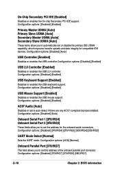
... [Enabled] Disables or enables the USB controller.Configuration options: [Disabled] [Enabled] USB 2.0 Controller [Enabled] Disables or enables the USB 2.0 controller. Configuration options: [Disabled] [Enabled] AC97 Audio [Auto] Disables or set the address of the onboard parallel port connector. Configuration options: [IrDA] [Normal] Onboard Parallel Port [378/IRQ7] This field allows you...
... [Enabled] Disables or enables the USB controller.Configuration options: [Disabled] [Enabled] USB 2.0 Controller [Enabled] Disables or enables the USB 2.0 controller. Configuration options: [Disabled] [Enabled] AC97 Audio [Auto] Disables or set the address of the onboard parallel port connector. Configuration options: [IrDA] [Normal] Onboard Parallel Port [378/IRQ7] This field allows you...
P4BP-MX 2.0 user's manual
Page 59
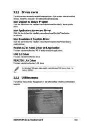
... Click this item to load the installation wizard and install the Intel® Application Accelerator. Realtek AC'97 Audio Driver and Application This item installs the Realtek® AC'97 audio driver and applications. ASUS P4BP-MX 2.0 motherboard 3-3 Install the necessary drivers to support USB 2.0. 3.2.3 Utilities menu The Utilities menu shows the applications and other...
... Click this item to load the installation wizard and install the Intel® Application Accelerator. Realtek AC'97 Audio Driver and Application This item installs the Realtek® AC'97 audio driver and applications. ASUS P4BP-MX 2.0 motherboard 3-3 Install the necessary drivers to support USB 2.0. 3.2.3 Utilities menu The Utilities menu shows the applications and other...
P4BP-MX 2.0 user's manual
Page 61
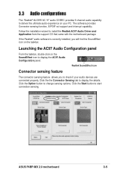
... SoundEffect icon Connector sensing feature The connector sensing feature allows you will find the SoundEffect icon on your audio devices are connected properly. ASUS P4BP-MX 2.0 motherboard 3-5 If the Realtek® audio software is correctly installed, you to install the Realtek AC97 Audio Driver and Application from the support CD that came with the motherboard package...
... SoundEffect icon Connector sensing feature The connector sensing feature allows you will find the SoundEffect icon on your audio devices are connected properly. ASUS P4BP-MX 2.0 motherboard 3-5 If the Realtek® audio software is correctly installed, you to install the Realtek AC97 Audio Driver and Application from the support CD that came with the motherboard package...

P4BP-MX 2.0 user's manual
Page 62
The Realtek® EZ-connection dialog box shows your audio cables are connected to the proper audio jack and repeat connector sensing. If there are detected problems, make sure that your current audio connections. Click the X button to exit audio control panel. 3-6 Chapter 3: Software support An X mark denotes an incorrect connection. Click the Exit (X) button on the upper-right hand corner of the box explains your audio connection status. The text at the bottom of the window to exit EZ-connection dialog box.
The Realtek® EZ-connection dialog box shows your audio cables are connected to the proper audio jack and repeat connector sensing. If there are detected problems, make sure that your current audio connections. Click the X button to exit audio control panel. 3-6 Chapter 3: Software support An X mark denotes an incorrect connection. Click the Exit (X) button on the upper-right hand corner of the box explains your audio connection status. The text at the bottom of the window to exit EZ-connection dialog box.

