Motherboard DIY Troubleshooting Guide
Page 3
... and updating your BIOS 2-2 2.1.1 Using ASUS EZ FLASH to update the BIOS 2-2 2.1.2 Using ASUS AFLASH to find more information vii ASUS contact information vii Specifications summary ix Chapter... 1 - Features Contents Contents iii FCC/CDC statements v Federal Communications Commission Statement v Canadian Department of Communications Statement v Safety information vi About this guide vii Conventions used in this guide vii Where to update the BIOS 2-4 Updating BIOS procedures 2-5 2.2 BIOS Setup Program 2-7 2.2.1 BIOS...
... and updating your BIOS 2-2 2.1.1 Using ASUS EZ FLASH to update the BIOS 2-2 2.1.2 Using ASUS AFLASH to find more information vii ASUS contact information vii Specifications summary ix Chapter... 1 - Features Contents Contents iii FCC/CDC statements v Federal Communications Commission Statement v Canadian Department of Communications Statement v Safety information vi About this guide vii Conventions used in this guide vii Where to update the BIOS 2-4 Updating BIOS procedures 2-5 2.2 BIOS Setup Program 2-7 2.2.1 BIOS...

Motherboard DIY Troubleshooting Guide
Page 9
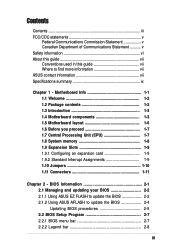
P4BGL-MX specifications summary CPU Chipset Front Side Bus (FSB) Memory Expansion slots IDE Audio LAN Special Features Back Panel I/O Ports Internal I/O Connectors Socket 478 ofr Intel ... PC2100/1600 non-ECC DDR SDRAM 3 x PCI 2 x UltraDMA 100/66 RealTek 2-channel CODEC RealTek 8101L PCI LAN integrated 10/100Mbps Fast Ethernet Power Loss Restart ASUS JumperFree BIOS write protections CPU Throttle 1 x Parallel 1 x Serial 1 x VGA 1 x PS/2 Keyboard 1 x PS/2 Mouse 4 x USB 2.0 1 x RJ-45 Port CPU/Chassis FAN connector 20 pin ATX power connector...
P4BGL-MX specifications summary CPU Chipset Front Side Bus (FSB) Memory Expansion slots IDE Audio LAN Special Features Back Panel I/O Ports Internal I/O Connectors Socket 478 ofr Intel ... PC2100/1600 non-ECC DDR SDRAM 3 x PCI 2 x UltraDMA 100/66 RealTek 2-channel CODEC RealTek 8101L PCI LAN integrated 10/100Mbps Fast Ethernet Power Loss Restart ASUS JumperFree BIOS write protections CPU Throttle 1 x Parallel 1 x Serial 1 x VGA 1 x PS/2 Keyboard 1 x PS/2 Mouse 4 x USB 2.0 1 x RJ-45 Port CPU/Chassis FAN connector 20 pin ATX power connector...
Motherboard DIY Troubleshooting Guide
Page 10
Manageability WfM2.0, DMI2.0, WOR by PME, WOL by BME Form Factor Micro-ATX form factor: 8.6 in x 9.6 in Support CD contents Device drivers ASUS PC Probe Trend Microtm PC-cillin 2002 anti-virus software ASUS LiveUpdate Utility Accessories User's manual Support CD 1 x USB Bracket IDE cable FDD cable * Specifications are subject to change without notice. x P4BGL-MX specifications summary BIOS features 2Mb Flash ROM, EEPROM, ASUS JumperFree, Award BIOS with ACPI, DMI2.0, PnP, WfM2.0, Green, TCAV (Trend Chip Away Virus) Industry standard PCI 2.2, USB 2.0.
Manageability WfM2.0, DMI2.0, WOR by PME, WOL by BME Form Factor Micro-ATX form factor: 8.6 in x 9.6 in Support CD contents Device drivers ASUS PC Probe Trend Microtm PC-cillin 2002 anti-virus software ASUS LiveUpdate Utility Accessories User's manual Support CD 1 x USB Bracket IDE cable FDD cable * Specifications are subject to change without notice. x P4BGL-MX specifications summary BIOS features 2Mb Flash ROM, EEPROM, ASUS JumperFree, Award BIOS with ACPI, DMI2.0, PnP, WfM2.0, Green, TCAV (Trend Chip Away Virus) Industry standard PCI 2.2, USB 2.0.

Motherboard DIY Troubleshooting Guide
Page 14
... others. 1-4 Chapter 1: Motherboard Information The power supply must have at least 1A on the +5V standby lead (+5VSB). 6 Super I /O, Flash BIOS, and PCI bus for the Intel® Pentium® 4 processor, a memory controller and an integrated graphics interface. 4 DDR DIMM Sockets. 1 ATX...PIO Modes 3 & 4 IDE devices. This Intel Brookdale GL controller integrates a high performance host interface for two PCI Slots. 11 ASUS ASIC. This interface provides the commonly used Super I/O functionality. These dual-channel bus master IDE connectors support up to prevent incorrect insertion ...
... others. 1-4 Chapter 1: Motherboard Information The power supply must have at least 1A on the +5V standby lead (+5VSB). 6 Super I /O, Flash BIOS, and PCI bus for the Intel® Pentium® 4 processor, a memory controller and an integrated graphics interface. 4 DDR DIMM Sockets. 1 ATX...PIO Modes 3 & 4 IDE devices. This Intel Brookdale GL controller integrates a high performance host interface for two PCI Slots. 11 ASUS ASIC. This interface provides the commonly used Super I/O functionality. These dual-channel bus master IDE connectors support up to prevent incorrect insertion ...

Motherboard DIY Troubleshooting Guide
Page 18
... on BIOS setup. 2. Assign an IRQ to avoid damaging the DIMM. 1.9 Expansion slots The P4BGL-MX motherboard has three (3) expansion slots. A DDR DIMM is keyed with a notch so that supports up to the tables below. 3. Refer to 2GB non-ECC PC2100/1600 DDR. 80 Pins P4BGL-MX 104 Pins P4BGL-MX 184-...Pin DDR DIMM Sockets 1. 1.8 System memory The motherboard has two Double Data Rate (DDR) DIMM sockets that it fits in only one direction. Install the software drivers for information on the system and change the necessary BIOS settings, if any....
... on BIOS setup. 2. Assign an IRQ to avoid damaging the DIMM. 1.9 Expansion slots The P4BGL-MX motherboard has three (3) expansion slots. A DDR DIMM is keyed with a notch so that supports up to the tables below. 3. Refer to 2GB non-ECC PC2100/1600 DDR. 80 Pins P4BGL-MX 104 Pins P4BGL-MX 184-...Pin DDR DIMM Sockets 1. 1.8 System memory The motherboard has two Double Data Rate (DDR) DIMM sockets that it fits in only one direction. Install the software drivers for information on the system and change the necessary BIOS settings, if any....
Motherboard DIY Troubleshooting Guide
Page 21
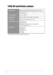
... down the key during the boot process and enter BIOS setup to [1-2] 4. P4BGL-MX P4BGL-MX Clear RTC RAM J1 12 23 Normal (Default) Clear CMOS 3. Plug the power cord and turn ON the computer. 6. P4BGL-MX KBPWR1 2 1 +5V (Default) 3 2 +5VSB (Default) P4BGL-MX Keyboard Power Setting ASUS P4BGL-MX Motherboard 1-11 You can supply at least 1A on the keyboard . Remove...
... down the key during the boot process and enter BIOS setup to [1-2] 4. P4BGL-MX P4BGL-MX Clear RTC RAM J1 12 23 Normal (Default) Clear CMOS 3. Plug the power cord and turn ON the computer. 6. P4BGL-MX KBPWR1 2 1 +5V (Default) 3 2 +5VSB (Default) P4BGL-MX Keyboard Power Setting ASUS P4BGL-MX Motherboard 1-11 You can supply at least 1A on the keyboard . Remove...

Motherboard DIY Troubleshooting Guide
Page 22
Refer to PIN 1. BIOS supports specific device bootup. PIN 1 1-12 Chapter 1: Motherboard Information one for the primary IDE connector and another UltraDMA100/66 cable. P4BGL-MX P4BGL-MX IDE Connectors SEC_IDE PRI_IDE NOTE: Orient the red markings (usually zigzag) on the UltraDMA cable connector. For UltraDMA100/66 IDE devices, use an 80-conductor ...
Refer to PIN 1. BIOS supports specific device bootup. PIN 1 1-12 Chapter 1: Motherboard Information one for the primary IDE connector and another UltraDMA100/66 cable. P4BGL-MX P4BGL-MX IDE Connectors SEC_IDE PRI_IDE NOTE: Orient the red markings (usually zigzag) on the UltraDMA cable connector. For UltraDMA100/66 IDE devices, use an 80-conductor ...
Motherboard DIY Troubleshooting Guide
Page 27
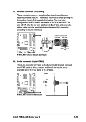
...IRRX GND IRTX Standard Infrared (SIR) Front View Back View SIR CIR IRTX +5V GND (NC) IRRX P4BGL-MX Infrared Module Connector 11. COM2 PIN 1 P4BGL-MX P4BGL-MX Serial COM2 Bracket ASUS P4BGL-MX Motherboard 1-17 Serial connector (9-pin COM2 ) This 9-pin connector connects to this feature. Connect the COM2...the module to the motherboard IR1 connector according to set UART2 for use with IR. Use the ten pins as shown in BIOS to the pin definitions. infrared connector (10-pin IR1) These connectors support an optional wireless transmitting and receiving infrared module. 10...
...IRRX GND IRTX Standard Infrared (SIR) Front View Back View SIR CIR IRTX +5V GND (NC) IRRX P4BGL-MX Infrared Module Connector 11. COM2 PIN 1 P4BGL-MX P4BGL-MX Serial COM2 Bracket ASUS P4BGL-MX Motherboard 1-17 Serial connector (9-pin COM2 ) This 9-pin connector connects to this feature. Connect the COM2...the module to the motherboard IR1 connector according to set UART2 for use with IR. Use the ten pins as shown in BIOS to the pin definitions. infrared connector (10-pin IR1) These connectors support an optional wireless transmitting and receiving infrared module. 10...

Motherboard DIY Troubleshooting Guide
Page 29
Pressing the power switch turns the system between ON and SLEEP, or ON and SOFT OFF, depending on the BIOS or OS settings. ASUS P4BGL-MX Motherboard 1-19 • System Warning Speaker Lead (4-pin SPEAKER) This 4-pin connector connects to the case-mounted speaker and allows you to hear system beeps ...
Pressing the power switch turns the system between ON and SLEEP, or ON and SOFT OFF, depending on the BIOS or OS settings. ASUS P4BGL-MX Motherboard 1-19 • System Warning Speaker Lead (4-pin SPEAKER) This 4-pin connector connects to the case-mounted speaker and allows you to hear system beeps ...
Motherboard DIY Troubleshooting Guide
Page 31
Chapter 2 This chapter gives information about the ASUS P4BGL-MX Binary Input/Output System (BIOS).This chapter includes updating the BIOS using the ASUS AFLASH BIOS that is bundled with the support CD. BIOS Information ASUS P4BGL-MX Motherboard 2-1
Chapter 2 This chapter gives information about the ASUS P4BGL-MX Binary Input/Output System (BIOS).This chapter includes updating the BIOS using the ASUS AFLASH BIOS that is bundled with the support CD. BIOS Information ASUS P4BGL-MX Motherboard 2-1
Motherboard DIY Troubleshooting Guide
Page 32
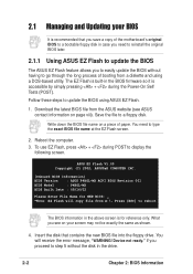
... a piece of booting from A:\, Press [ESC] to update the BIOS using a DOS-based utility. Follow these steps to reboot The BIOS information in the drive. 2-2 Chapter 2: BIOS Information ASUS EZ Flash V1.00 Copyright (C) 2002, ASUSTeK COMPUTER INC. [Onboard BIOS Information] BIOS Version : ASUS P4BGL-MX ACPI BIOS Revision 001 BIOS Model : P4BGL-MX BIOS Built Date : 09/16/02 Please Enter File Name...
... a piece of booting from A:\, Press [ESC] to update the BIOS using a DOS-based utility. Follow these steps to reboot The BIOS information in the drive. 2-2 Chapter 2: BIOS Information ASUS EZ Flash V1.00 Copyright (C) 2002, ASUSTeK COMPUTER INC. [Onboard BIOS Information] BIOS Version : ASUS P4BGL-MX ACPI BIOS Revision 001 BIOS Model : P4BGL-MX BIOS Built Date : 09/16/02 Please Enter File Name...
Motherboard DIY Troubleshooting Guide
Page 33
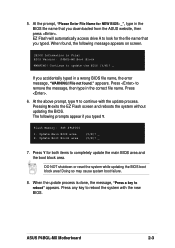
... N exits the EZ Flash screen and reboots the system without updating the BIOS. Update Main BIOS area 2. ASUS P4BGL-MX Motherboard 2-3 At the prompt, "Please Enter File Name for NEW BIOS: _", type in the correct file name. File not found , the following prompts appear if you typed. Press . 6....name that you accidentally typed in File] BIOS Version: P4BGL-MX Boot Block WARNING! At the above prompt, type Y to update the BIOS (Y/N)? _ If you downloaded from the ASUS website, then press . Press any key to completely update the main BIOS area and the boot block area. EZ ...
... N exits the EZ Flash screen and reboots the system without updating the BIOS. Update Main BIOS area 2. ASUS P4BGL-MX Motherboard 2-3 At the prompt, "Please Enter File Name for NEW BIOS: _", type in the correct file name. File not found , the following prompts appear if you typed. Press . 6....name that you accidentally typed in File] BIOS Version: P4BGL-MX Boot Block WARNING! At the above prompt, type Y to update the BIOS (Y/N)? _ If you downloaded from the ASUS website, then press . Press any key to completely update the main BIOS area and the boot block area. EZ ...

Motherboard DIY Troubleshooting Guide
Page 34
... of your CD-ROM drive) to copy AFLASH.EXE to the boot disk you see on your screen may be programmed by uploading a new BIOS file to the programmable flash ROM on the upper left-hand corner of the code displayed on the motherboard. Type COPY D:\AFLASH\AFLASH.EXE A:\ (assuming D... is not supported by the ACPI BIOS and therefore, cannot be loaded when you reboot using a floppy disk. 3. In DOS mode, type A:\AFLASH to the disk. 2. If the word "unknown" appears after...
... of your CD-ROM drive) to copy AFLASH.EXE to the boot disk you see on your screen may be programmed by uploading a new BIOS file to the programmable flash ROM on the upper left-hand corner of the code displayed on the motherboard. Type COPY D:\AFLASH\AFLASH.EXE A:\ (assuming D... is not supported by the ACPI BIOS and therefore, cannot be loaded when you reboot using a floppy disk. 3. In DOS mode, type A:\AFLASH to the disk. 2. If the word "unknown" appears after...
Motherboard DIY Troubleshooting Guide
Page 35
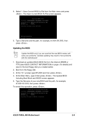
... of your problems. Careless updating may result to File from the Main menu and press . The Update BIOS Including Boot Block and ESCD screen appears. 5. To cancel this operation, press . ASUS P4BGL-MX Motherboard 2-5 Select 1. Download an updated ASUS BIOS file from the floppy disk. 3. At the Main Menu, type 2 then press . Type a filename and the...
... of your problems. Careless updating may result to File from the Main menu and press . The Update BIOS Including Boot Block and ESCD screen appears. 5. To cancel this operation, press . ASUS P4BGL-MX Motherboard 2-5 Select 1. Download an updated ASUS BIOS file from the floppy disk. 3. At the Main Menu, type 2 then press . Type a filename and the...

Motherboard DIY Troubleshooting Guide
Page 36
The boot block is not able to successfully update a complete BIOS file, call the ASUS service center for support. 2-6 Chapter 2: BIOS Information DO NOT turn off the system while updating the BIOS. Follow the onscreen instructions to the boot disk. This may cause boot problems. Just repeat the process, and if the problem persists, load...
The boot block is not able to successfully update a complete BIOS file, call the ASUS service center for support. 2-6 Chapter 2: BIOS Information DO NOT turn off the system while updating the BIOS. Follow the onscreen instructions to the boot disk. This may cause boot problems. Just repeat the process, and if the problem persists, load...
Motherboard DIY Troubleshooting Guide
Page 37
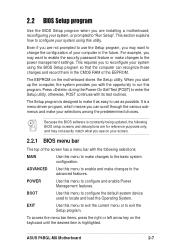
... program when you are for reference purposes only, and may not exactly match what you see on your screen. 2.2.1 BIOS menu bar The top of your computer in the CMOS RAM of the EEPROM. This section explains how to configure your system, or prompted to ... through the various submenus and make it as easy to "Run Setup". Even if you are not prompted to use as possible. Because the BIOS software is highlighted. ASUS P4BGL-MX Motherboard 2-7 This requires you can recognize these changes and record them in the future. The EEPROM on the keyboard until the desired item...
... program when you are for reference purposes only, and may not exactly match what you see on your screen. 2.2.1 BIOS menu bar The top of your computer in the CMOS RAM of the EEPROM. This section explains how to configure your system, or prompted to ... through the various submenus and make it as easy to "Run Setup". Even if you are not prompted to use as possible. Because the BIOS software is highlighted. ASUS P4BGL-MX Motherboard 2-7 This requires you can recognize these changes and record them in the future. The EEPROM on the keyboard until the desired item...

Motherboard DIY Troubleshooting Guide
Page 38
...highlighted field Brings up and down arrow keys to its Setup Defaults Saves changes and exits Setup General help window, press or . 2-8 Chapter 2: BIOS Information Saving changes and exiting the Setup program See "2.7 Exit Menu" for the highlighted field or Moves the cursor to the first field or Moves...bottom of a help document. The following table lists the keys found in the legend bar allow you to the Item Specific Help window, the BIOS setup program also provides a General Help screen. Press to display the first page, press to go to the main menu from any menu ...
...highlighted field Brings up and down arrow keys to its Setup Defaults Saves changes and exits Setup General help window, press or . 2-8 Chapter 2: BIOS Information Saving changes and exiting the Setup program See "2.7 Exit Menu" for the highlighted field or Moves the cursor to the first field or Moves...bottom of a help document. The following table lists the keys found in the legend bar allow you to the Item Specific Help window, the BIOS setup program also provides a General Help screen. Press to display the first page, press to go to the main menu from any menu ...

Motherboard DIY Troubleshooting Guide
Page 40
...diskette. Configuration options: [All Errors] [No Error] [All but Keyboard] [All but Disk] [All but Disk/Keyboard] 2-10 Chapter 2: BIOS Information The Floppy 3 Mode feature allows reading and writing of 1.2MB (as above appears. Symbols and other characters are accepted. The password is ... in a password then press . Forgot the password? Type in .] Floppy 3 Mode Support [Disabled] This is now set to set to the BIOS during system startup. The RAM data containing the password information is month, day, year. You can clear it by the onboard button cell battery. ...
...diskette. Configuration options: [All Errors] [No Error] [All but Keyboard] [All but Disk] [All but Disk/Keyboard] 2-10 Chapter 2: BIOS Information The Floppy 3 Mode feature allows reading and writing of 1.2MB (as above appears. Symbols and other characters are accepted. The password is ... in a password then press . Forgot the password? Type in .] Floppy 3 Mode Support [Disabled] This is now set to set to the BIOS during system startup. The RAM data containing the password information is month, day, year. You can clear it by the onboard button cell battery. ...
Motherboard DIY Troubleshooting Guide
Page 42
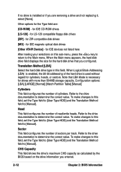
...-120 compatible floppy disk drives [ZIP] - for the Type field are removing a drive and not replacing it, select [None]. Note that you entered. 2-12 Chapter 2: BIOS Information To make changes to this sub-menu, press the key to return to [Manual]. CHS Capacity This field shows the drive's maximum CHS capacity... as calculated by the BIOS based on this field, set the Type field to [User Type HDD] and the Translation Method field to determine the correct value.
...-120 compatible floppy disk drives [ZIP] - for the Type field are removing a drive and not replacing it, select [None]. Note that you entered. 2-12 Chapter 2: BIOS Information To make changes to this sub-menu, press the key to return to [Manual]. CHS Capacity This field shows the drive's maximum CHS capacity... as calculated by the BIOS based on this field, set the Type field to [User Type HDD] and the Translation Method field to determine the correct value.

Motherboard DIY Troubleshooting Guide
Page 43
... HDD]. Multi-Sector Transfers [Maximum] This option automatically sets the number of sectors per block to suppress Ultra DMA capability. Configuration options: [0] [1] [2] [3] [4] [5] [Disabled] 2.3.2 Keyboard Features ASUS P4BGL-MX Motherboard 2-13 Set to [Disabled] to the highest number that when this field. Note that the drive supports. Maximum LBA Capacity This field shows the...
... HDD]. Multi-Sector Transfers [Maximum] This option automatically sets the number of sectors per block to suppress Ultra DMA capability. Configuration options: [0] [1] [2] [3] [4] [5] [Disabled] 2.3.2 Keyboard Features ASUS P4BGL-MX Motherboard 2-13 Set to [Disabled] to the highest number that when this field. Note that the drive supports. Maximum LBA Capacity This field shows the...


