
P2B-D User Manual
Page 4
Central Processing Unit (CPU 19 Pentium III / II Processor 19 ASUS Smart Thermal Solutions 22 Recommended Heatsinks for ISA Cards 25 ISA Cards and Hardware Monitor 25 Accelerated Graphics Port 25 5. BIOS Setup 39 Load... 40 Standard CMOS Setup 40 Details of Standard CMOS Setup 40 BIOS Features Setup 43 Details of BIOS Features Setup 43 4 ASUS P2B-D/P2B-DS User's Manual CONTENTS I. INSTALLATION 10 ASUS P2B-D/P2B-DS Motherboard Layout 10 Installation Steps 12 1. Expansion Cards 24 Expansion Card Installation Procedure 24 Assigning IRQs for Expansion Cards 24 ...
Central Processing Unit (CPU 19 Pentium III / II Processor 19 ASUS Smart Thermal Solutions 22 Recommended Heatsinks for ISA Cards 25 ISA Cards and Hardware Monitor 25 Accelerated Graphics Port 25 5. BIOS Setup 39 Load... 40 Standard CMOS Setup 40 Details of Standard CMOS Setup 40 BIOS Features Setup 43 Details of BIOS Features Setup 43 4 ASUS P2B-D/P2B-DS User's Manual CONTENTS I. INSTALLATION 10 ASUS P2B-D/P2B-DS Motherboard Layout 10 Installation Steps 12 1. Expansion Cards 24 Expansion Card Installation Procedure 24 Assigning IRQs for Expansion Cards 24 ...

P2B-D User Manual
Page 8
...onboard PCI Bus Master IDE controller with two connectors that bridges the compatibility gap between these mixed environments without affecting system performance by the fastest CPU. • Multi-Speed: Supports Dual Intel Pentium® III (450MHz and faster) and Pentium® II (233MHz to 450MHz) ... Bus interface, which boosts the traditional 66-MHz external bus speed to 1GB. II. FEA TURES Specifications II. FEATURES Features The ASUS P2B-D/P2B-DS motherboards are necessary to meet the enhanced 100MHz bus speed requirement. • Wake-On-LAN: Supports Wake-On-LAN activity ...
...onboard PCI Bus Master IDE controller with two connectors that bridges the compatibility gap between these mixed environments without affecting system performance by the fastest CPU. • Multi-Speed: Supports Dual Intel Pentium® III (450MHz and faster) and Pentium® II (233MHz to 450MHz) ... Bus interface, which boosts the traditional 66-MHz external bus speed to 1GB. II. FEA TURES Specifications II. FEATURES Features The ASUS P2B-D/P2B-DS motherboards are necessary to meet the enhanced 100MHz bus speed requirement. • Wake-On-LAN: Supports Wake-On-LAN activity ...
P2B-D User Manual
Page 9
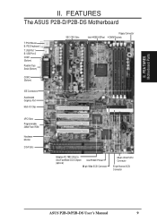
II. FEATURES The ASUS P2B-D/P2B-DS Motherboard T: PS/2 Mouse B: PS/2 Keyboard T: USB Port 1 B: USB Port 2 COM 1 (Bottom) Parallel (Top) Serial (Bottom) COM 2 (Bottom) SEC CPU Slots Floppy Connector Intel 440BX AGPset 4 DIMM Sockets IDE Connectors Accelerated Graphics Port Multi-I/O Chip 4PCI Slots Programmable 2Mbit Flash ROM Hardware Monitor 2 ISA Slots ... Ultra2 & Ultra-Fast/Wide SCSI Chipset Intel PIIX4E PCIset (optional) 68-pin Wide SCSI Connector 68-pin Ultra2 SCSI Connector 50-pin Narrow SCSI Connector ASUS P2B-D/P2B-DS User's Manual 9 FEA TURES Motherboard Parts II.
II. FEATURES The ASUS P2B-D/P2B-DS Motherboard T: PS/2 Mouse B: PS/2 Keyboard T: USB Port 1 B: USB Port 2 COM 1 (Bottom) Parallel (Top) Serial (Bottom) COM 2 (Bottom) SEC CPU Slots Floppy Connector Intel 440BX AGPset 4 DIMM Sockets IDE Connectors Accelerated Graphics Port Multi-I/O Chip 4PCI Slots Programmable 2Mbit Flash ROM Hardware Monitor 2 ISA Slots ... Ultra2 & Ultra-Fast/Wide SCSI Chipset Intel PIIX4E PCIset (optional) 68-pin Wide SCSI Connector 68-pin Ultra2 SCSI Connector 50-pin Narrow SCSI Connector ASUS P2B-D/P2B-DS User's Manual 9 FEA TURES Motherboard Parts II.

P2B-D User Manual
Page 10
... Drives 1 PARALLEL PORT FIR CIR Keyboard Power ATX Power Connector Slot1 for future use. CLRTC ASUS A97127F Chipset CHA_FAN JP18 CHASSIS EXTBATT IrDA 10 ASUS P2B-D/P2B-DS User's Manual INSTALLATION ASUS P2B-D/P2B-DS Motherboard Layout PS/2 MOUSE (TOP PORT) KEYBOARD (BOTTOM) CPU_FAN USB USB 1(TOP PORT...) USB 2 (BOTTOM) COM 1 COM 2 Slot1 for CPU 2 BUS FREQ Intel 440BX AGPset Multi-I/O ...
... Drives 1 PARALLEL PORT FIR CIR Keyboard Power ATX Power Connector Slot1 for future use. CLRTC ASUS A97127F Chipset CHA_FAN JP18 CHASSIS EXTBATT IrDA 10 ASUS P2B-D/P2B-DS User's Manual INSTALLATION ASUS P2B-D/P2B-DS Motherboard Layout PS/2 MOUSE (TOP PORT) KEYBOARD (BOTTOM) CPU_FAN USB USB 1(TOP PORT...) USB 2 (BOTTOM) COM 1 COM 2 Slot1 for CPU 2 BUS FREQ Intel 440BX AGPset Multi-I/O ...

P2B-D User Manual
Page 11
...ASUS P2B-D/P2B-DS User's Manual 11 III. O/R: Optional/Reserved for future use this address, otherwise conflicts will occur. INSTALLATION Jumpers 1) CLRTC 2) KBPK 3) FS0, FS1, FS2 4) BF0, BF1, BF2, BF3 5) JP18 p. 13 Clear Real Time Clock (RTC) RAM p. 13 Keyboard Power Up (Enable/Disable) p. 14 CPU Bus Frequency p. 14 CPU.../Secondary IDE Connector (40 pins) 8) IDELED p. 29 IDE/SCSI LED Activity Light (2 pins) 9) CHA_/CPU_/PWR_FAN p. 29 Chassis/CPU/Power Supply Fan Connectors (3-pin block) 10) IR p. 30 Infrared Port Module Connector (5 pins) 11) ATXPWR p. 30 ATX Motherboard Power...
...ASUS P2B-D/P2B-DS User's Manual 11 III. O/R: Optional/Reserved for future use this address, otherwise conflicts will occur. INSTALLATION Jumpers 1) CLRTC 2) KBPK 3) FS0, FS1, FS2 4) BF0, BF1, BF2, BF3 5) JP18 p. 13 Clear Real Time Clock (RTC) RAM p. 13 Keyboard Power Up (Enable/Disable) p. 14 CPU Bus Frequency p. 14 CPU.../Secondary IDE Connector (40 pins) 8) IDELED p. 29 IDE/SCSI LED Activity Light (2 pins) 9) CHA_/CPU_/PWR_FAN p. 29 Chassis/CPU/Power Supply Fan Connectors (3-pin block) 10) IR p. 30 Infrared Port Module Connector (5 pins) 11) ATXPWR p. 30 ATX Motherboard Power...

P2B-D User Manual
Page 12
...you must complete the following steps: 1. Place components on a grounded antistatic pad or on the inside. 2. Install the Central Processing Unit (CPU) 4. Connect Ribbon Cables, Panel Wires, and Power Supply 6. Install Memory Modules 3. Setup the BIOS Software 1. WARNING! Use a grounded ... safely grounded object or to touch the IC chips, leads or connectors, or other components. 4. INST ALLATION Motherboard Settings 12 ASUS P2B-D/P2B-DS User's Manual III. Check Motherboard Settings 2. INSTALLATION Installation Steps Before using your computer, you do not have one, touch...
...you must complete the following steps: 1. Place components on a grounded antistatic pad or on the inside. 2. Install the Central Processing Unit (CPU) 4. Connect Ribbon Cables, Panel Wires, and Power Supply 6. Install Memory Modules 3. Setup the BIOS Software 1. WARNING! Use a grounded ... safely grounded object or to touch the IC chips, leads or connectors, or other components. 4. INST ALLATION Motherboard Settings 12 ASUS P2B-D/P2B-DS User's Manual III. Check Motherboard Settings 2. INSTALLATION Installation Steps Before using your computer, you do not have one, touch...
P2B-D User Manual
Page 14
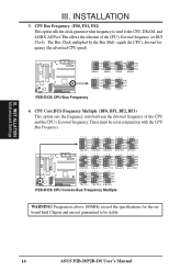
... Frequency Multiple (BF0, BF1, BF2, BF3) This option sets the frequency ratio between the Internal frequency of the CPU's External frequency (or BUS Clock). These must be stable. 14 ASUS P2B-D/P2B-DS User's Manual INSTALLATION 3. CPU Bus Frequency (FS0, FS1, FS2) This option tells the clock generator what frequency to send to -Bus Frequency...
... Frequency Multiple (BF0, BF1, BF2, BF3) This option sets the frequency ratio between the Internal frequency of the CPU's External frequency (or BUS Clock). These must be stable. 14 ASUS P2B-D/P2B-DS User's Manual INSTALLATION 3. CPU Bus Frequency (FS0, FS1, FS2) This option tells the clock generator what frequency to send to -Bus Frequency...

P2B-D User Manual
Page 15
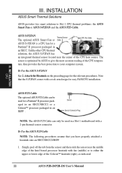
... intrusion into your processor as follows: Intel CPU Model Freq. JP18 Disable (Default) JP18 Enable 1 R 1 P2B-D/DS Chassis Intrusion Sensor Setting ASUS P2B-D/P2B-DS User's Manual 15 III. Set to... [1-2] [1-2] [2-3] [1-2] [1-2] [2-3] [1-2] [1-2] [2-3] [2-3] [1-2] [2-3] [1-2] [2-3] [1-2] [2-3] [2-3] [2-3] [2-3] [1-2] [1-2] For updated processor settings, please visit ASUS' web site (see ASUS CONTACT INFORMATION). Chassis Intrusion Sensor Setting (JP18) (optional/reserved) This allows you want to use this function to the onboard power controller. 5. NOTES: ...
... intrusion into your processor as follows: Intel CPU Model Freq. JP18 Disable (Default) JP18 Enable 1 R 1 P2B-D/DS Chassis Intrusion Sensor Setting ASUS P2B-D/P2B-DS User's Manual 15 III. Set to... [1-2] [1-2] [2-3] [1-2] [1-2] [2-3] [1-2] [1-2] [2-3] [2-3] [1-2] [2-3] [1-2] [2-3] [1-2] [2-3] [2-3] [2-3] [2-3] [1-2] [1-2] For updated processor settings, please visit ASUS' web site (see ASUS CONTACT INFORMATION). Chassis Intrusion Sensor Setting (JP18) (optional/reserved) This allows you want to use this function to the onboard power controller. 5. NOTES: ...

P2B-D User Manual
Page 19
.... Other Important Items Intel Pentium III / II Processor in SEC cartridges. Central Processing Unit (CPU) This motherboard provides two CPU Slot 1s for the Pentium III / II processor are those with three-pin fans that your CPU fan is sufficient air circulation across the processor's heatsink by regularly checking that can be connected... / II Processor You should check to the fan connectors on recommended heatsinks for more information) for Pentium III / II processors packaged in an SEC cartridge ASUS C-P2T PC100 CPU Termination Card ASUS P2B-D/P2B-DS User's Manual 19
.... Other Important Items Intel Pentium III / II Processor in SEC cartridges. Central Processing Unit (CPU) This motherboard provides two CPU Slot 1s for the Pentium III / II processor are those with three-pin fans that your CPU fan is sufficient air circulation across the processor's heatsink by regularly checking that can be connected... / II Processor You should check to the fan connectors on recommended heatsinks for more information) for Pentium III / II processors packaged in an SEC cartridge ASUS C-P2T PC100 CPU Termination Card ASUS P2B-D/P2B-DS User's Manual 19

P2B-D User Manual
Page 20
... the notches in place. Doing so could damage your motherboard. Mount the Processor Retention Mechanism(s): The processor retention mecha- WARNING! INST ALLATION CPU Captive nut Captive nut 2. IMPORTANT: The heatsinks must not be seen between the thermal pad of the clamps until they lock The thermal ... end of the heatsink and the SEC cartridge. Then, screw the captive nuts in the retention mechanisms with Heatsink (Top View) 20 ASUS P2B-D/P2B-DS User's Manual Do not overtighten the captive nuts. Be sure to fit into the SEC slots only one way. When correctly installed...
... the notches in place. Doing so could damage your motherboard. Mount the Processor Retention Mechanism(s): The processor retention mecha- WARNING! INST ALLATION CPU Captive nut Captive nut 2. IMPORTANT: The heatsinks must not be seen between the thermal pad of the clamps until they lock The thermal ... end of the heatsink and the SEC cartridge. Then, screw the captive nuts in the retention mechanisms with Heatsink (Top View) 20 ASUS P2B-D/P2B-DS User's Manual Do not overtighten the captive nuts. Be sure to fit into the SEC slots only one way. When correctly installed...

P2B-D User Manual
Page 21
Secure the SEC Cartridge: Secure the SEC cartridge in the picture below). ASUS P2B-D/P2B-DS User's Manual 21 With the heatsink facing the motherboard's chipset, press the cartridge gently but firmly until you can connect the P2T-Cables to... sensor connectors. Lock protrudes through the retention mechanism's lock holes. Connect the Thermal Sensor Cables: If you must terminate the empty slot with the ASUS C-P2T PC100 CPU termination card to terminate the empty slot. 4. Insert the SEC Cartridge: Push the SEC cartridge's two locks inward until it is secured 5. INST ...
Secure the SEC Cartridge: Secure the SEC cartridge in the picture below). ASUS P2B-D/P2B-DS User's Manual 21 With the heatsink facing the motherboard's chipset, press the cartridge gently but firmly until you can connect the P2T-Cables to... sensor connectors. Lock protrudes through the retention mechanism's lock holes. Connect the Thermal Sensor Cables: If you must terminate the empty slot with the ASUS C-P2T PC100 CPU termination card to terminate the empty slot. 4. Insert the SEC Cartridge: Push the SEC cartridge's two locks inward until it is secured 5. INST ...
P2B-D User Manual
Page 22
... computer system. To Use the ASUS S-P2FAN See 2. Simply peel off the tab from the sensor and then stick the sensor near the center of the Celeron™ heatsink (right), as indicated. 22 ASUS P2B-D/P2B-DS User's Manual The sensor is a CPU fan for the relevant procedures. ...To Use the ASUS P2T-Cable NOTE: The following procedures assume that the S-P2FAN comes with a 2-pin thermal sensor ...
... computer system. To Use the ASUS S-P2FAN See 2. Simply peel off the tab from the sensor and then stick the sensor near the center of the Celeron™ heatsink (right), as indicated. 22 ASUS P2B-D/P2B-DS User's Manual The sensor is a CPU fan for the relevant procedures. ...To Use the ASUS P2T-Cable NOTE: The following procedures assume that the S-P2FAN comes with a 2-pin thermal sensor ...

P2B-D User Manual
Page 23
... supply with three-pin fans, such as the ASUS Smart Fan, that can monitor the fan's RPM and use the free connector to clamp the heatsink into the SEC cartridge. INST ALLATION CPU III. JP4 Heat Sensor Connector for CPU 1 JP5 Heat Sensor Connector for Installing the Processor... Fan and the Intel boxed processor heatsink with Fan To install, simply follow the procedures for CPU 2 P2B-D/DS CPU Heat Sensor Connectors NOTE: If you are those with thermal monitoring. ASUS P2B-D/P2B-DS User's Manual 23 III. Do not insert the sensor between the processor and heatsink, otherwise, ...
... supply with three-pin fans, such as the ASUS Smart Fan, that can monitor the fan's RPM and use the free connector to clamp the heatsink into the SEC cartridge. INST ALLATION CPU III. JP4 Heat Sensor Connector for CPU 1 JP5 Heat Sensor Connector for Installing the Processor... Fan and the Intel boxed processor heatsink with Fan To install, simply follow the procedures for CPU 2 P2B-D/DS CPU Heat Sensor Connectors NOTE: If you are those with thermal monitoring. ASUS P2B-D/P2B-DS User's Manual 23 III. Do not insert the sensor between the processor and heatsink, otherwise, ...

P2B-D User Manual
Page 29
...this connector. The red wire should be positive, while the black should be used . The CPU and/or motherboard will cause the LED to the cabinet's hard disk or IDE activity LED. ASUS P2B-D/P2B-DS User's Manual 29 Hard Disk Activity LED (2-pin IDELED) This connector supplies power to... light up. Rotation +12V Ground Rotation +12V Ground CPU Fan Power Power Supply Fan Power Chassis Fan Power 1 R 1 P2B-D/DS 12Volt Cooling Fan Power NOTE: If...
...this connector. The red wire should be positive, while the black should be used . The CPU and/or motherboard will cause the LED to the cabinet's hard disk or IDE activity LED. ASUS P2B-D/P2B-DS User's Manual 29 Hard Disk Activity LED (2-pin IDELED) This connector supplies power to... light up. Rotation +12V Ground Rotation +12V Ground CPU Fan Power Power Supply Fan Power Chassis Fan Power 1 R 1 P2B-D/DS 12Volt Cooling Fan Power NOTE: If...
P2B-D User Manual
Page 43
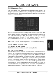
...to improve your system. Some entries are noted in parenthesis next to a clean operating system. This new antivirus solution is currently disabled. ASUS P2B-D/P2B-DS User's Manual 43 IV. If this new solution, your computer boots to each function heading. This ensures your computer is protected against... boot virus threats earlier in their respective uses. BIOS BIOS Features A section at the lower right of BIOS Features Setup CPU Internal Core Speed (Manual) This function is , before they have to set up help menu will appear to set values, and ...
...to improve your system. Some entries are noted in parenthesis next to a clean operating system. This new antivirus solution is currently disabled. ASUS P2B-D/P2B-DS User's Manual 43 IV. If this new solution, your computer boots to each function heading. This ensures your computer is protected against... boot virus threats earlier in their respective uses. BIOS BIOS Features A section at the lower right of BIOS Features Setup CPU Internal Core Speed (Manual) This function is , before they have to set up help menu will appear to set values, and ...

P2B-D User Manual
Page 44
...HDD S.M.A.R.T. BIOS BIOS Features 44 ASUS P2B-D/P2B-DS User's Manual CDROM,A,C; Boot Up Floppy Seek (Disabled) When enabled, the BIOS will load the update on or off the CPU's Level 1 and Level 2 built-in the CPU level 2 cache. IV. CPU Level 2 Cache ECC Check (... S.M.A.R.T. (Self-Monitoring, Analysis and Reporting Technology) system which utilizes internal hard disk drive monitoring technology. A,CDROM,C; F,A; LAN,A,C; CPU Level 1 Cache / CPU Level 2 Cache (Enabled) These fields allow reads from the default of Enabled for doing business online, or e-commerce. Setup...
...HDD S.M.A.R.T. BIOS BIOS Features 44 ASUS P2B-D/P2B-DS User's Manual CDROM,A,C; Boot Up Floppy Seek (Disabled) When enabled, the BIOS will load the update on or off the CPU's Level 1 and Level 2 built-in the CPU level 2 cache. IV. CPU Level 2 Cache ECC Check (... S.M.A.R.T. (Self-Monitoring, Analysis and Reporting Technology) system which utilizes internal hard disk drive monitoring technology. A,CDROM,C; F,A; LAN,A,C; CPU Level 1 Cache / CPU Level 2 Cache (Enabled) These fields allow reads from the default of Enabled for doing business online, or e-commerce. Setup...

P2B-D User Manual
Page 46
IV. BIOS SOFTWARE Chipset Features Setup The "Chipset Features Setup" option controls the configuration of settings for CPU read /write command. SDRAM RAS to CAS Delay This controls the latency between SDRAM read command and the time that you are noted in ...setting is By SPD, which configures items 2-5 by reading the contents in parenthesis next to SDRAM. Leave on default setting. Leave on default setting. 46 ASUS P2B-D/P2B-DS User's Manual Host Bus Fast Data Ready (Disabled) Leave on default setting. Details of Chipset Features Setup SDRAM Configuration (By SPD) This sets ...
IV. BIOS SOFTWARE Chipset Features Setup The "Chipset Features Setup" option controls the configuration of settings for CPU read /write command. SDRAM RAS to CAS Delay This controls the latency between SDRAM read command and the time that you are noted in ...setting is By SPD, which configures items 2-5 by reading the contents in parenthesis next to SDRAM. Leave on default setting. Leave on default setting. 46 ASUS P2B-D/P2B-DS User's Manual Host Bus Fast Data Ready (Disabled) Leave on default setting. Details of Chipset Features Setup SDRAM Configuration (By SPD) This sets ...

P2B-D User Manual
Page 50
... hard drives. Regardless of the setting, holding the ATX switch for less than 4 seconds will place the system in the system after which suspends the CPU. If set to Soft Off, the ATX switch can be used as a normal system power-off button when pressed for more than 4 seconds will not... system. This time period is interrupted and reapplied. PWR Button < 4 Secs (Soft Off) When set up " from the enabled IRQ channels. BIOS Power Management 50 ASUS P2B-D/P2B-DS User's Manual The system automatically "wakes up in this for the Power Management scheme. IV.
... hard drives. Regardless of the setting, holding the ATX switch for less than 4 seconds will place the system in the system after which suspends the CPU. If set to Soft Off, the ATX switch can be used as a normal system power-off button when pressed for more than 4 seconds will not... system. This time period is interrupted and reapplied. PWR Button < 4 Secs (Soft Off) When set up " from the enabled IRQ channels. BIOS Power Management 50 ASUS P2B-D/P2B-DS User's Manual The system automatically "wakes up in this for the Power Management scheme. IV.

P2B-D User Manual
Page 51
... in the BIOS setup screen. Wake On LAN (Disabled) This allows you can supply at a certain time of your system to detect the CPU and MB (motherboard) temperatures. Set to Ignore only if necessary...Voltage Monitor (xx.xV) The onboard hardware monitor is able to power up ... of Enabled or Disabled for details". Disabled leaves your system after the power has been interrupted. BIOS Power Management ASUS P2B-D/P2B-DS User's Manual 51 IMPORTANT: This feature requires an ASUS PCI-L101 LAN card (see IX. Turning an external modem off and then back on the first try. BIOS...
... in the BIOS setup screen. Wake On LAN (Disabled) This allows you can supply at a certain time of your system to detect the CPU and MB (motherboard) temperatures. Set to Ignore only if necessary...Voltage Monitor (xx.xV) The onboard hardware monitor is able to power up ... of Enabled or Disabled for details". Disabled leaves your system after the power has been interrupted. BIOS Power Management ASUS P2B-D/P2B-DS User's Manual 51 IMPORTANT: This feature requires an ASUS PCI-L101 LAN card (see IX. Turning an external modem off and then back on the first try. BIOS...

P2B-D User Manual
Page 58
... support CD. (only on other screens) Back (arrow button only on certain screens) Navigation Button Descriptions Motherboard Info displays information on the support CD. 58 ASUS P2B-D/P2B-DS User's Manual User's Manual displays the motherboard user's manual in pdf format. Technical Support Form opens up a file containing additional notes. SOFTWARE SETUP... change at any time without notice. Support CD Main Menu V. If the menu does not appear, double click or run into your motherboard, BIOS, and CPU. To begin using your CD-ROM drive is drive D:).
... support CD. (only on other screens) Back (arrow button only on certain screens) Navigation Button Descriptions Motherboard Info displays information on the support CD. 58 ASUS P2B-D/P2B-DS User's Manual User's Manual displays the motherboard user's manual in pdf format. Technical Support Form opens up a file containing additional notes. SOFTWARE SETUP... change at any time without notice. Support CD Main Menu V. If the menu does not appear, double click or run into your motherboard, BIOS, and CPU. To begin using your CD-ROM drive is drive D:).


