
User Manual
Page 3
... Guide for later use. 2. R Removing the storage drive assembly 1. English Internal components 3 2 4 5 7 6 1. 2. 3. 4. 1 5. 6. 7. Keep the screws for motherboard details. Front panel cover 5.25-inch optical drive and 3.5-inch hard disk drive cage Power supply unit PCI/PCIE card riser bracket (connected to the... motherboard PCI/PCIE slot) ASUS motherboard* DIMM sockets CPU socket NOTE: *Refer to the right, remove it, and set it aside. Locate the front panel...
... Guide for later use. 2. R Removing the storage drive assembly 1. English Internal components 3 2 4 5 7 6 1. 2. 3. 4. 1 5. 6. 7. Keep the screws for motherboard details. Front panel cover 5.25-inch optical drive and 3.5-inch hard disk drive cage Power supply unit PCI/PCIE card riser bracket (connected to the... motherboard PCI/PCIE slot) ASUS motherboard* DIMM sockets CPU socket NOTE: *Refer to the right, remove it, and set it aside. Locate the front panel...
User Manual
Page 4
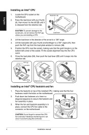
English Installing an Intel® CPU 1. Position the CPU over the socket, making sure that the gold triangle is on the motherboard. Close the load plate (6A), then push the load lever (6B) until it is in the direction of the socket. B 3. CAUTION. Lift the load lever ...; angle (4A), then push the PnP cap from the retention tab. Push down two fasteners at a time in place. Locate the CPU socket on the motherboard. 2. Press the load lever with your thumb (A), then move it snaps into the CPU notch. 6. CAUTION! PnP cap 6A Load plate 4B 4A Gold triangle...
English Installing an Intel® CPU 1. Position the CPU over the socket, making sure that the gold triangle is on the motherboard. Close the load plate (6A), then push the load lever (6B) until it is in the direction of the socket. B 3. CAUTION. Lift the load lever ...; angle (4A), then push the PnP cap from the retention tab. Push down two fasteners at a time in place. Locate the CPU socket on the motherboard. 2. Press the load lever with your thumb (A), then move it snaps into the CPU notch. 6. CAUTION! PnP cap 6A Load plate 4B 4A Gold triangle...
User Manual
Page 5
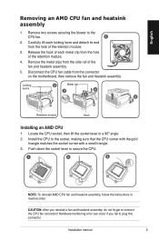
... heatsink assembly, do not forget to plug this connector. Release the hook of each locking lever and detach its end from the connector on the motherboard, then remove the fan and heatsink assembly. Carefully lift each metal clip from the side rail of the retention module. 4. Locking 2 Metal clip levers 3 4 4 5 Retention...
... heatsink assembly, do not forget to plug this connector. Release the hook of each locking lever and detach its end from the connector on the motherboard, then remove the fan and heatsink assembly. Carefully lift each metal clip from the side rail of the retention module. 4. Locking 2 Metal clip levers 3 4 4 5 Retention...
User Manual
Page 6
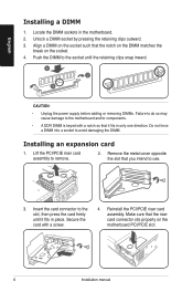
... a DIMM socket by pressing the retaining clips outward. 3. Installing an expansion card 1. Secure the card with a notch so that you intend to the motherboard and/or components. • A DDR DIMM is keyed with a screw. 4. Lift the PCI/PCIE riser card assembly to avoid damaging the DIMM. ... not force a DIMM into a socket to remove. 2. English Installing a DIMM 1. Push the DIMM to the socket until it fits in the motherboard. 2. Remove the metal cover opposite the slot that it fits in place. Reinstall the PCI/PCIE riser card assembly. Align a DIMM on the socket...
... a DIMM socket by pressing the retaining clips outward. 3. Installing an expansion card 1. Secure the card with a notch so that you intend to the motherboard and/or components. • A DDR DIMM is keyed with a screw. 4. Lift the PCI/PCIE riser card assembly to avoid damaging the DIMM. ... not force a DIMM into a socket to remove. 2. English Installing a DIMM 1. Push the DIMM to the socket until it fits in the motherboard. 2. Remove the metal cover opposite the slot that it fits in place. Reinstall the PCI/PCIE riser card assembly. Align a DIMM on the socket...


