
User Manual
Page 2
...revision number are released for each board design represented by the purchaser for identification purposes only. For previous or updated manuals, BIOS, drivers, or product release information you may be registered trademarks or copyrights of their respective companies. • Intel, ...Product Name: ASUS P/I-P55T2P4 Manual Revision: 3.11 Release Date: May 1997 II ASUS P/I-P55T2P4 User's Manual ASUS provides this manual or product. ASUS may revise this product, including the product and software may visit the ASUS home page at http://www.asus.com.tw/ or contact ASUS from the ...
...revision number are released for each board design represented by the purchaser for identification purposes only. For previous or updated manuals, BIOS, drivers, or product release information you may be registered trademarks or copyrights of their respective companies. • Intel, ...Product Name: ASUS P/I-P55T2P4 Manual Revision: 3.11 Release Date: May 1997 II ASUS P/I-P55T2P4 User's Manual ASUS provides this manual or product. ASUS may revise this product, including the product and software may visit the ASUS home page at http://www.asus.com.tw/ or contact ASUS from the ...

User Manual
Page 4
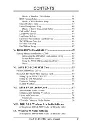
...Memory Writer Utility 26 Main Menu 26 Advanced Features Menu 27 Updating your Motherboard's BIOS 28 6. BIOS Setup 29 Load Defaults 30 Standard CMOS Setup 30 IV ASUS P/I . FEATURES 2 Features of the ASUS Motherboard 2 Parts of the Motherboard 4 Installation Steps 6 1. Jumpers 6 Jumper ...for Expansion Cards 16 Assigning DMA Channels for this manual is organized 1 Item Checklist 1 II. CONTENTS I -P55T2P4 User's Manual INSTALLATION 4 Map of the ASUS Motherboard 3 III. System Memory (DRAM & SRAM 12 TAG SRAM Upgrade 12 DRAM Memory Installation Procedures 13 Static ...
...Memory Writer Utility 26 Main Menu 26 Advanced Features Menu 27 Updating your Motherboard's BIOS 28 6. BIOS Setup 29 Load Defaults 30 Standard CMOS Setup 30 IV ASUS P/I . FEATURES 2 Features of the ASUS Motherboard 2 Parts of the Motherboard 4 Installation Steps 6 1. Jumpers 6 Jumper ...for Expansion Cards 16 Assigning DMA Channels for this manual is organized 1 Item Checklist 1 II. CONTENTS I -P55T2P4 User's Manual INSTALLATION 4 Map of the ASUS Motherboard 3 III. System Memory (DRAM & SRAM 12 TAG SRAM Upgrade 12 DRAM Memory Installation Procedures 13 Static ...
User Manual
Page 5
... Audio Card Bundle Only) IX. DOS 3.1 & Windows 3.1x Audio Software (with optional ASUS I-A16C Audio Card Bundle Only) ASUS P/I-P55T2P4 User's Manual V CONTENTS Details of Standard CMOS Setup 31 BIOS Features Setup 34 Details of BIOS Features Setup 34 Chipset Features Setup 37 Power Management Setup 40 Details of Power Management Setup 40 PNP and...
... Audio Card Bundle Only) IX. DOS 3.1 & Windows 3.1x Audio Software (with optional ASUS I-A16C Audio Card Bundle Only) ASUS P/I-P55T2P4 User's Manual V CONTENTS Details of Standard CMOS Setup 31 BIOS Features Setup 34 Details of BIOS Features Setup 34 Chipset Features Setup 37 Power Management Setup 40 Details of Power Management Setup 40 PNP and...

User Manual
Page 7
...BIOS Setup: BIOS software setup information. V. Features: Information and specifications concerning this manual is organized This manual is complete. ASUS SCSI: Installation of an optional 16-bit Audio card VIII. I . Software: Information on setting up the motherboard. DOS/Win3.1x: Audio Software Manual (with mounting bracket Optional ASUS pipelined burst cache module ASUS P/I-P55T2P4... package is divided into the following sections: I -A16C bundle) IX. The ASUS P/I-P55T2P4 motherboard 2 serial port ribbon cables attached to a mounting bracket 1 parallel ribbon ...
...BIOS Setup: BIOS software setup information. V. Features: Information and specifications concerning this manual is organized This manual is complete. ASUS SCSI: Installation of an optional 16-bit Audio card VIII. I . Software: Information on setting up the motherboard. DOS/Win3.1x: Audio Software Manual (with mounting bracket Optional ASUS pipelined burst cache module ASUS P/I-P55T2P4... package is divided into the following sections: I -A16C bundle) IX. The ASUS P/I-P55T2P4 motherboard 2 serial port ribbon cables attached to a mounting bracket 1 parallel ribbon ...

User Manual
Page 8
...of either 5.25" or 3.5" (1.44MB or 2.88MB) are made through BIOS which includes two functions in a small package. The Japanese "Floppy 3 mode" (3.5" 1.2MB) floppy standard is also supported. 2 ASUS P/I -P55T2P4 is carefully designed for the demanding PC user who wants a great many features... in one PCI/MediaBus 2.0 which allows the use of the ASUS Motherboard The ASUS P/I -P55T2P4 User's Manual FEATURES (Features) II. Two floppy drives of either a standard PCI card or the ASUS MediaBus Card. • ASUS MediaBus Rev 2.0: Features an expansion slot extension shared with PCI ...
...of either 5.25" or 3.5" (1.44MB or 2.88MB) are made through BIOS which includes two functions in a small package. The Japanese "Floppy 3 mode" (3.5" 1.2MB) floppy standard is also supported. 2 ASUS P/I -P55T2P4 is carefully designed for the demanding PC user who wants a great many features... in one PCI/MediaBus 2.0 which allows the use of the ASUS Motherboard The ASUS P/I -P55T2P4 User's Manual FEATURES (Features) II. Two floppy drives of either a standard PCI card or the ASUS MediaBus Card. • ASUS MediaBus Rev 2.0: Features an expansion slot extension shared with PCI ...

User Manual
Page 9
...: This motherboard supports an optional infrared port module for wireless interface and a PS/2 mouse cable set. • NCR SCSI BIOS: This motherboard has firmware that supports four IDE devices in two channels, provides faster data transfer rates, and supports Enhanced IDE ... controller with two connectors that supports the optional ASUS PCI-SC200 SCSI controller cards. FEATURES (Parts of the ASUS Motherboard 3 ISA Slots Programmable Flash ROM 3 PCI Slots Parallel & Serial Ports Super Multi-I -P55T2P4 User's Manual 3 PCI 4 or ASUS MediaBus 2.0 (4) 72-pin SIMM Sockets Upgradeable...
...: This motherboard supports an optional infrared port module for wireless interface and a PS/2 mouse cable set. • NCR SCSI BIOS: This motherboard has firmware that supports four IDE devices in two channels, provides faster data transfer rates, and supports Enhanced IDE ... controller with two connectors that supports the optional ASUS PCI-SC200 SCSI controller cards. FEATURES (Parts of the ASUS Motherboard 3 ISA Slots Programmable Flash ROM 3 PCI Slots Parallel & Serial Ports Super Multi-I -P55T2P4 User's Manual 3 PCI 4 or ASUS MediaBus 2.0 (4) 72-pin SIMM Sockets Upgradeable...

User Manual
Page 12
...DRAM and SRAM Modules 3. Install the Central Processing Unit (CPU) 4. Jumpers with the keyboard connector away from the system. 6 ASUS P/I-P55T2P4 User's Manual Unplug your computer, you work on the board. Place components on a grounded antistatic pad or on the motherboard. ... tions of the Motherboard" on the inside. 2. Hold components by the edges and try not to connect pins 2&3. Setup the BIOS Software 1. Jumpers Several hardware settings are separated from yourself. To protect the motherboard and other components against damage from other groups....
...DRAM and SRAM Modules 3. Install the Central Processing Unit (CPU) 4. Jumpers with the keyboard connector away from the system. 6 ASUS P/I-P55T2P4 User's Manual Unplug your computer, you work on the board. Place components on a grounded antistatic pad or on the motherboard. ... tions of the Motherboard" on the inside. 2. Hold components by the edges and try not to connect pins 2&3. Setup the BIOS Software 1. Jumpers Several hardware settings are separated from yourself. To protect the motherboard and other components against damage from other groups....
User Manual
Page 13
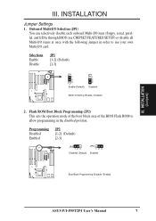
Flash ROM Boot Block Programming (JP2) This sets the operation mode of the boot block area of the BIOS Flash ROM to use your own Multi-I /O items at once with the following jumper in order to allow programming in the Enabled position.... Onboard Multi-I/O Selection (JP1) You can selectively disable each onboard Multi-I/O item (floppy, serial, parallel, and IrDA) through BIOS (see CHIPSET FEATURES SETUP) or disable all Multi-I /O card. Programming Disabled Enabled JP2 [1-2] (Default) [2-3] JP2 123 Disabled (Default) JP2 123 Enabled Boot Block...
Flash ROM Boot Block Programming (JP2) This sets the operation mode of the boot block area of the BIOS Flash ROM to use your own Multi-I /O items at once with the following jumper in order to allow programming in the Enabled position.... Onboard Multi-I/O Selection (JP1) You can selectively disable each onboard Multi-I/O item (floppy, serial, parallel, and IrDA) through BIOS (see CHIPSET FEATURES SETUP) or disable all Multi-I /O card. Programming Disabled Enabled JP2 [1-2] (Default) [2-3] JP2 123 Disabled (Default) JP2 123 Enabled Boot Block...

User Manual
Page 14
...) Clear Data [short] (momentarily) JP7 JP7 Operation (Default) Clear Data RTC RAM (Operation / Clear Data) 8 ASUS P/I-P55T2P4 User's Manual III. Selections JP5 256KB [1-2] 512KB [2-3] JP5 1 2 3 256KB JP5 1 2 3 512KB Total L2 Cache Size Setting (256KB / ...512KB) 4. An "ASUS" or "COAST" cache module can be used to upgrade the 256KB version to re-enter user preferences. Regardless of your... PC, (5) Remove this jumper, (6) Power on the PC, (7) Hold down during bootup and enter BIOS setup to 512KB.
...) Clear Data [short] (momentarily) JP7 JP7 Operation (Default) Clear Data RTC RAM (Operation / Clear Data) 8 ASUS P/I-P55T2P4 User's Manual III. Selections JP5 256KB [1-2] 512KB [2-3] JP5 1 2 3 256KB JP5 1 2 3 512KB Total L2 Cache Size Setting (256KB / ...512KB) 4. An "ASUS" or "COAST" cache module can be used to upgrade the 256KB version to re-enter user preferences. Regardless of your... PC, (5) Remove this jumper, (6) Power on the PC, (7) Hold down during bootup and enter BIOS setup to 512KB.

User Manual
Page 18
System Memory (DRAM & SRAM) This motherboard supports four 72-pin SIMMs of the banks in any or all modules. Install memory in BIOS Chipset Setup "Auto Configuration" on the same side as shown by the Top view with more than 24 chips per module. INSTALLATION (Memory) IMPORTANT...Memory Cacheable Size" jumper. IMPORTANT: Each bank must have an extended tag, do not install another TAG SRAM into the TAG SRAM Upgrade Socket. 12 ASUS P/I-P55T2P4 User's Manual Do not use a standard 5Volt SRAM chip that you must use memory modules with the semicircle "Indention" on page 34. Top Side ...
System Memory (DRAM & SRAM) This motherboard supports four 72-pin SIMMs of the banks in any or all modules. Install memory in BIOS Chipset Setup "Auto Configuration" on the same side as shown by the Top view with more than 24 chips per module. INSTALLATION (Memory) IMPORTANT...Memory Cacheable Size" jumper. IMPORTANT: Each bank must have an extended tag, do not install another TAG SRAM into the TAG SRAM Upgrade Socket. 12 ASUS P/I-P55T2P4 User's Manual Do not use a standard 5Volt SRAM chip that you must use memory modules with the semicircle "Indention" on page 34. Top Side ...
User Manual
Page 22
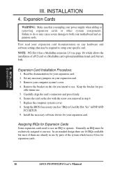
... expansion card. 3. Install the necessary software drivers for your computer system's cover. 4. Assigning IRQs for expansion cards. 16 ASUS P/I-P55T2P4 User's Manual Keep the bracket for your motherboard and expansion cards. Set any hardware and software settings that you removed in PNPAND... PCI SETUP) 9. Remove your expansion card. Carefully align the card's connectors and press firmly. 6. Setup the BIOS if necessary (such as "IRQ xx Used By ISA: Yes" in step 4. 7. INSTALLATION (Expansion Cards) III. Expansion Card Installation ...
... expansion card. 3. Install the necessary software drivers for your computer system's cover. 4. Assigning IRQs for expansion cards. 16 ASUS P/I-P55T2P4 User's Manual Keep the bracket for your motherboard and expansion cards. Set any hardware and software settings that you removed in PNPAND... PCI SETUP) 9. Remove your expansion card. Carefully align the card's connectors and press firmly. 6. Setup the BIOS if necessary (such as "IRQ xx Used By ISA: Yes" in step 4. 7. INSTALLATION (Expansion Cards) III. Expansion Card Installation ...
User Manual
Page 23
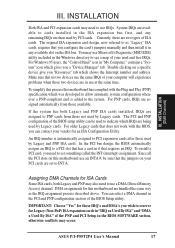
...and then install it that the jumpers on the ISA bus. In the PCI bus design, the BIOS automatically assigns an IRQ to reserve for this motherboard use a DMA (Direct Memory Access) channel. ASUS P/I-P55T2P4 User's Manual 17 You can select a DMA channel in "My Computer," contains a "System" icon...for those IRQ's and DMA's you need to PCI expansion cards after those not used by Legacy cards. System IRQs are in the BIOS SOFTWARE section, otherwise conflicts may use Microsoft's Diagnostic (MSD.EXE) utility included in the Windows directory to PNP cards from those two ...
...and then install it that the jumpers on the ISA bus. In the PCI bus design, the BIOS automatically assigns an IRQ to reserve for this motherboard use a DMA (Direct Memory Access) channel. ASUS P/I-P55T2P4 User's Manual 17 You can select a DMA channel in "My Computer," contains a "System" icon...for those IRQ's and DMA's you need to PCI expansion cards after those not used by Legacy cards. System IRQs are in the BIOS SOFTWARE section, otherwise conflicts may use Microsoft's Diagnostic (MSD.EXE) utility included in the Windows directory to PNP cards from those two ...
User Manual
Page 25
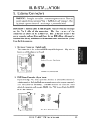
... are labeled on page 4. III. The four corners of the connectors are clearly separated from jumpers in BIOS FEATURES SETUP. 1 234 58 1 234 58 1: GND 2: DATA 3: NC 4: VCC 5: CLK 8: NC PS/2 Mouse Module Connector ASUS P/I-P55T2P4 User's Manual 19 PS/2 Mouse Connector (6-pin block) If you must be less than 18in. (46cm), with...
... are labeled on page 4. III. The four corners of the connectors are clearly separated from jumpers in BIOS FEATURES SETUP. 1 234 58 1 234 58 1: GND 2: DATA 3: NC 4: VCC 5: CLK 8: NC PS/2 Mouse Module Connector ASUS P/I-P55T2P4 User's Manual 19 PS/2 Mouse Connector (6-pin block) If you must be less than 18in. (46cm), with...
User Manual
Page 26
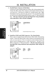
... Connect the ribbon cable to this connection and mount the bracket to the case on the mounting bracket will then be available for BIOS configuration of "Onboard Serial Port". (Pin 10 is removed to prevent inserting in the wrong orientation when using ribbon cables with pin...cable. III. INSTALLATION 3. COM 1 Pin 1 COM 2 Pin 1 Onboard Serial Port Connectors 20 ASUS P/I-P55T2P4 User's Manual INSTALLATION (Connectors) III. You can enable the parallel port and choose the IRQ through BIOS Setup on an open slot. Serial Port COM1 and COM2 Connectors (Two 10-pin blocks) These ...
... Connect the ribbon cable to this connection and mount the bracket to the case on the mounting bracket will then be available for BIOS configuration of "Onboard Serial Port". (Pin 10 is removed to prevent inserting in the wrong orientation when using ribbon cables with pin...cable. III. INSTALLATION 3. COM 1 Pin 1 COM 2 Pin 1 Onboard Serial Port Connectors 20 ASUS P/I-P55T2P4 User's Manual INSTALLATION (Connectors) III. You can enable the parallel port and choose the IRQ through BIOS Setup on an open slot. Serial Port COM1 and COM2 Connectors (Two 10-pin blocks) These ...
User Manual
Page 28
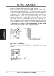
... (see "HDD Sequence SCSI/IDE First" & "Boot Sequence" in the BIOS FEATURES SETUP of the BIOS software) (Pin 20 is removed to the documentation of your hard disk(s). Pin 1 Secondary IDE Connector Primary IDE Connector 8. III. IDE LED + IDE Activity LED 22 ASUS P/I-P55T2P4 User's Manual Please refer to prevent inserting in the wrong...
... (see "HDD Sequence SCSI/IDE First" & "Boot Sequence" in the BIOS FEATURES SETUP of the BIOS software) (Pin 20 is removed to the documentation of your hard disk(s). Pin 1 Secondary IDE Connector Primary IDE Connector 8. III. IDE LED + IDE Activity LED 22 ASUS P/I-P55T2P4 User's Manual Please refer to prevent inserting in the wrong...
User Manual
Page 29
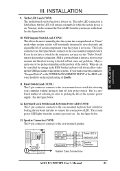
... Power LED (CON1) This 5-pin connector connects to the case-mounted keyboard lock switch for the connector, you want to prolong the life of the BIOS software should be controlled by settings in use. See the figure below . 13. See the figure below . 12. Speaker Connector (CON1) This 4-pin ...GND SMI Lead GND Reset SW GND +5V NC Power LED & GND LOCK Keyboard Lock GND +5V GND Speaker GND Connector SPKR System Case Connections ASUS P/I-P55T2P4 User's Manual 23 You may use this lead. If you may wish to connect the Power LED from the system case to this connector, "...
... Power LED (CON1) This 5-pin connector connects to the case-mounted keyboard lock switch for the connector, you want to prolong the life of the BIOS software should be controlled by settings in use. See the figure below . 13. See the figure below . 12. Speaker Connector (CON1) This 4-pin ...GND SMI Lead GND Reset SW GND +5V NC Power LED & GND LOCK Keyboard Lock GND +5V GND Speaker GND Connector SPKR System Case Connections ASUS P/I-P55T2P4 User's Manual 23 You may use this lead. If you may wish to connect the Power LED from the system case to this connector, "...
User Manual
Page 30
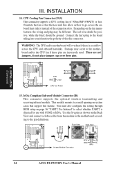
.... You must also configure the setting through BIOS setup on system cases that the heat sink fins allow airflow to the pin definitions. Orientate the fan so that support this connector. Front View Back View +5V IRRX IRTX NC GND Infrared Module Connector IRTX +5V GND NC IRRX 24 ASUS P/I-P55T2P4 User's Manual
.... You must also configure the setting through BIOS setup on system cases that the heat sink fins allow airflow to the pin definitions. Orientate the fan so that support this connector. Front View Back View +5V IRRX IRTX NC GND Infrared Module Connector IRTX +5V GND NC IRRX 24 ASUS P/I-P55T2P4 User's Manual
User Manual
Page 31
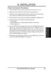
... light and the monitor LED as instructed by your system case as well. III. The power LED on the screen. Follow the next section "BIOS SOFTWARE" for assistance. 7. Make sure that is equipped by . 3. The system will appear on the front panel of your system user's manual... your jumper settings and connections or call your devices in the off position as marked by a surge protector. 5. INSTALLATION (Power Connections) ASUS P/I-P55T2P4 User's Manual 25 III. You may have failed a power-on tests. Your monitor b. While the tests are in the following order: a.
... light and the monitor LED as instructed by your system case as well. III. The power LED on the screen. Follow the next section "BIOS SOFTWARE" for assistance. 7. Make sure that is equipped by . 3. The system will appear on the front panel of your system user's manual... your jumper settings and connections or call your devices in the off position as marked by a surge protector. 5. INSTALLATION (Power Connections) ASUS P/I-P55T2P4 User's Manual 25 III. You may have failed a power-on tests. Your monitor b. While the tests are in the following order: a.
User Manual
Page 32
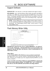
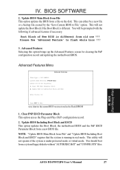
... programmable or not supported with the support software. Save Current BIOS To File 2. If "unknown" is shown after "Flash type --," then this section to "Save Current BIOS to copy the contents of the following: 1. BIOS (Flash Memory Writer) 26 ASUS P/I-P55T2P4 User's Manual To determine the BIOS version, check the last four numbers of the code...
... programmable or not supported with the support software. Save Current BIOS To File 2. If "unknown" is shown after "Flash type --," then this section to "Save Current BIOS to copy the contents of the following: 1. BIOS (Flash Memory Writer) 26 ASUS P/I-P55T2P4 User's Manual To determine the BIOS version, check the last four numbers of the code...
User Manual
Page 33
... or a backup file created by the "Save Current BIOS to flash whole bios !!! 3. Advanced Features Menu Advanced Features Flash Type -- BIOS (Flash Memory Writer) ASUS P/I-P55T2P4 User's Manual 27 You will not operate if the system is different. Update BIOS Main Block from File This option updates the BIOS from a system floppy diskette without "AUTOEXEC.BAT" and...
... or a backup file created by the "Save Current BIOS to flash whole bios !!! 3. Advanced Features Menu Advanced Features Flash Type -- BIOS (Flash Memory Writer) ASUS P/I-P55T2P4 User's Manual 27 You will not operate if the system is different. Update BIOS Main Block from File This option updates the BIOS from a system floppy diskette without "AUTOEXEC.BAT" and...


