
User Manual
Page 1
Motherboard Maximus II Formula
Motherboard Maximus II Formula
User Manual
Page 3
... Contents...iii Notices...viii Safety information ix About this guide x Maximus II Formula specifications summary xii Chapter 1: Product introduction 1.1 Welcome 1-1 1.2 Package contents 1-1 1.3 Special features 1-2 1.3.1 Product highlights 1-2 1.3.2 ROG Intelligent Performance & Overclocking features... 1-4 1.3.3 ROG unique features 1-6 1.3.4 ASUS special features 1-7 Chapter 2: Hardware information 2.1 Before you proceed 2-1 2.2 Motherboard overview 2-4 2.2.1 Motherboard layout 2-4 2.2.2 SupremeFX-Fi audio card layout 2-4 2.2.3 Layout contents 2-5 2.2.4 Placement direction...
... Contents...iii Notices...viii Safety information ix About this guide x Maximus II Formula specifications summary xii Chapter 1: Product introduction 1.1 Welcome 1-1 1.2 Package contents 1-1 1.3 Special features 1-2 1.3.1 Product highlights 1-2 1.3.2 ROG Intelligent Performance & Overclocking features... 1-4 1.3.3 ROG unique features 1-6 1.3.4 ASUS special features 1-7 Chapter 2: Hardware information 2.1 Before you proceed 2-1 2.2 Motherboard overview 2-4 2.2.1 Motherboard layout 2-4 2.2.2 SupremeFX-Fi audio card layout 2-4 2.2.3 Layout contents 2-5 2.2.4 Placement direction...
User Manual
Page 12
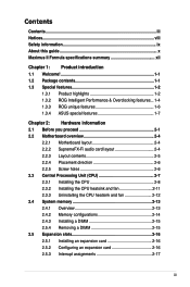
Maximus II Formula specifications summary CPU Chipset System Bus Memory Expansion Slots CrossFire™ Technology Storage LAN High Definition Audio LGA775 socket for Intel® Core™2 Extreme / ...™2 Quad / Core™2 Duo / Pentium® dual-core / Celeron® dualcore / Celeron® processors Intel® EM64T / EIST / Hyper-Threading Technology * Refer to www.asus.com for up to 16 GB system memory *Refer to 2 PATA devices - 1 x External SATA 3.0 Gb/s port (SATA On-the-Go) Silicon Image SIL5723 controller: - 2 x SATA...
Maximus II Formula specifications summary CPU Chipset System Bus Memory Expansion Slots CrossFire™ Technology Storage LAN High Definition Audio LGA775 socket for Intel® Core™2 Extreme / ...™2 Quad / Core™2 Duo / Pentium® dual-core / Celeron® dualcore / Celeron® processors Intel® EM64T / EIST / Hyper-Threading Technology * Refer to www.asus.com for up to 16 GB system memory *Refer to 2 PATA devices - 1 x External SATA 3.0 Gb/s port (SATA On-the-Go) Silicon Image SIL5723 controller: - 2 x SATA...
User Manual
Page 13
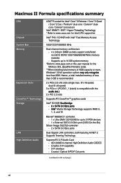
...phase power design for Northbridge - 2-phase power design for Memory iROG Extreme Tweaker Loadline Calibration Intelligent overclocking tools: - O.C. Maximus II Formula specifications summary IEEE 1394 USB ROG Exclusive Overclocking features ROG Special Features Back Panel I/O Ports 2 x IEEE 1394a ports (one... at rear panel) 12 x USB 2.0 ports (6 ports onboard; 6 ports at rear panel) ASUS EPU-Six Engine ASUS Fan Xpert ASUS Q-Shield ASUS Q-Connector ASUS EZ Flash 2 ASUS MyLogo 3™ 1 x PS/2 Keyboard port 1 x eSATA port 1 x IEEE1394a port 2 x LAN (RJ45) ports 6 ...
...phase power design for Northbridge - 2-phase power design for Memory iROG Extreme Tweaker Loadline Calibration Intelligent overclocking tools: - O.C. Maximus II Formula specifications summary IEEE 1394 USB ROG Exclusive Overclocking features ROG Special Features Back Panel I/O Ports 2 x IEEE 1394a ports (one... at rear panel) 12 x USB 2.0 ports (6 ports onboard; 6 ports at rear panel) ASUS EPU-Six Engine ASUS Fan Xpert ASUS Q-Shield ASUS Q-Connector ASUS EZ Flash 2 ASUS MyLogo 3™ 1 x PS/2 Keyboard port 1 x eSATA port 1 x IEEE1394a port 2 x LAN (RJ45) ports 6 ...
User Manual
Page 14
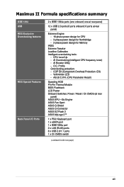
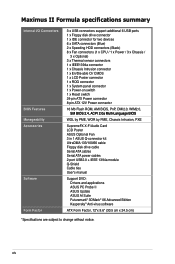
xiv Maximus II Formula specifications summary Internal I/O Connectors BIOS Features Manageability Accessories Software Form Factor 3 x USB connectors support additional 6 USB ports 1 x Floppy disk drive connector 1 x IDE connector for two ... drive cable Serial ATA cables Serial ATA power cables 2-port USB2.0 + IEEE 1394a module Q-Shield Cable ties User's manual Support DVD: Drivers and applications ASUS PC Probe II ASUS Update ASUS AI Suite Futuremark® 3DMark® 06 Advanced Edition Kaspersky® Anti-virus software ATX Form Factor, 12"x 9.6" (30.5 cm x 24.5 cm) *Specifications...
xiv Maximus II Formula specifications summary Internal I/O Connectors BIOS Features Manageability Accessories Software Form Factor 3 x USB connectors support additional 6 USB ports 1 x Floppy disk drive connector 1 x IDE connector for two ... drive cable Serial ATA cables Serial ATA power cables 2-port USB2.0 + IEEE 1394a module Q-Shield Cable ties User's manual Support DVD: Drivers and applications ASUS PC Probe II ASUS Update ASUS AI Suite Futuremark® 3DMark® 06 Advanced Edition Kaspersky® Anti-virus software ATX Form Factor, 12"x 9.6" (30.5 cm x 24.5 cm) *Specifications...
User Manual
Page 17
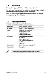
..., making it , check the items in your package with the list below. 1.2 Package contents Check your motherboard package for buying an ASUS® Maximus II Formula motherboard! ASUS Maximus II Formula 1-1 1.1 Welcome! Thank you start installing the motherboard, and hardware devices on it another standout in -1 ASUS Q-Connector Kit Q-Shield Cable ties Application DVD ASUS motherboard support DVD Documentation User guide If any of...
..., making it , check the items in your package with the list below. 1.2 Package contents Check your motherboard package for buying an ASUS® Maximus II Formula motherboard! ASUS Maximus II Formula 1-1 1.1 Welcome! Thank you start installing the motherboard, and hardware devices on it another standout in -1 ASUS Q-Connector Kit Q-Shield Cable ties Application DVD ASUS motherboard support DVD Documentation User guide If any of...
User Manual
Page 19
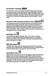
... PC portable devices. IEEE 1394a support The IEEE 1394a interface provides high speed digital interface for high-speed data retrieval and saves. ASUS Maximus II Formula 1-3 This capability ensures rapid transfer of data from WAN to different destinations. You can now talk to get high quality images....a real-time 3D-rendered previews within ATI Catalyst™ Control Center. Serial ATA 3.0 Gb/s technology and SATA-On-The-Go This motherboard supports the next-generation hard drives based on the headphones while playing multi-channel network games. See pages 2-22, 2-25, and 2-...
... PC portable devices. IEEE 1394a support The IEEE 1394a interface provides high speed digital interface for high-speed data retrieval and saves. ASUS Maximus II Formula 1-3 This capability ensures rapid transfer of data from WAN to different destinations. You can now talk to get high quality images....a real-time 3D-rendered previews within ATI Catalyst™ Control Center. Serial ATA 3.0 Gb/s technology and SATA-On-The-Go This motherboard supports the next-generation hard drives based on the headphones while playing multi-channel network games. See pages 2-22, 2-25, and 2-...
User Manual
Page 21
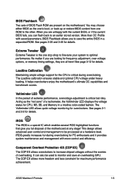
... with more freedom and less constraint for the CPU is the one ROM to optimal performance. iROG greatly increases fun during overclocking. ASUS Maximus II Formula 1-5 More than OC Profile with the current BIOS, or if the current BIOS fails, you full disposal of BIOS Flash ROM ...intuitive color-coded fashion. See page 3-12 for frequency adjustment, over-voltage options, or memory timing settings, they are present on the motherboard. This design allows advanced user control and management to be used to save an overheating GPU. The COP EX allows more control and...
... with more freedom and less constraint for the CPU is the one ROM to optimal performance. iROG greatly increases fun during overclocking. ASUS Maximus II Formula 1-5 More than OC Profile with the current BIOS, or if the current BIOS fails, you full disposal of BIOS Flash ROM ...intuitive color-coded fashion. See page 3-12 for frequency adjustment, over-voltage options, or memory timing settings, they are present on the motherboard. This design allows advanced user control and management to be used to save an overheating GPU. The COP EX allows more control and...
User Manual
Page 23
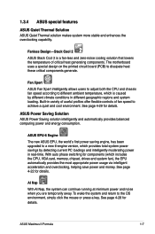
With auto phase switching for details. The motherboard uses a special design on the printed circuit board (PCB) to the OS environment, simply click the mouse or press a key. Fan Xpert ASUS Fan Xpert intelligently allows users to adjust both the CPU and chassis fan speed according to ...time. AI Nap With AI Nap, the system can continue running at minimum power and noise when you are temporarily away. ASUS Maximus II Formula 1-7 ASUS EPU-6 Engine The new ASUS EPU, the world's first power saving engine, has been upgraded to achieve a quiet and cool environment. To wake the...
With auto phase switching for details. The motherboard uses a special design on the printed circuit board (PCB) to the OS environment, simply click the mouse or press a key. Fan Xpert ASUS Fan Xpert intelligently allows users to adjust both the CPU and chassis fan speed according to ...time. AI Nap With AI Nap, the system can continue running at minimum power and noise when you are temporarily away. ASUS Maximus II Formula 1-7 ASUS EPU-6 Engine The new ASUS EPU, the world's first power saving engine, has been upgraded to achieve a quiet and cool environment. To wake the...
User Manual
Page 26
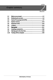
Chapter summary 2 2.1 Before you proceed 2-1 2.2 Motherboard overview 2-4 2.3 Central Processing Unit (CPU 2-7 2.4 System memory 2-13 2.5 Expansion slots 2-16 2.6 Jumpers 2-19 2.7....C.o.n.n.e.c.to.r.s 2-21 2.8 Installing accessories 2-36 2.9 Starting up for the first time 2-39 2.10 Turning off the computer 2-40 ASUS Maximus II Formula
Chapter summary 2 2.1 Before you proceed 2-1 2.2 Motherboard overview 2-4 2.3 Central Processing Unit (CPU 2-7 2.4 System memory 2-13 2.5 Expansion slots 2-16 2.6 Jumpers 2-19 2.7....C.o.n.n.e.c.to.r.s 2-21 2.8 Installing accessories 2-36 2.9 Starting up for the first time 2-39 2.10 Turning off the computer 2-40 ASUS Maximus II Formula
User Manual
Page 27
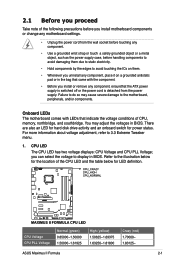
... strap or touch a safely grounded object or a metal object, such as the power supply case, before you install motherboard components or change any component, place it on a grounded antistatic pad or in BIOS. ASUS Maximus II Formula 2-1 2.1 Before you proceed Take note of the following precautions before handling components to avoid damaging them due to...
... strap or touch a safely grounded object or a metal object, such as the power supply case, before you install motherboard components or change any component, place it on a grounded antistatic pad or in BIOS. ASUS Maximus II Formula 2-1 2.1 Before you proceed Take note of the following precautions before handling components to avoid damaging them due to...

User Manual
Page 29
... hard disk LED is ON, in sleep mode, or in any motherboard component. Wait till the flash stops before you should shut down the system and unplug the power cable before removing or plugging in soft‑off mode. ASUS Maximus II Formula 2-3 This is a reminder that you press the power-on the ...drive connected to indicate the hard disk activity. The LED does not light up to boot. When you turn on switch. Power LED The motherboard comes with a power-on switch. The illustration below shows the location of the onboard power-on switch that the system is designed to the...
... hard disk LED is ON, in sleep mode, or in any motherboard component. Wait till the flash stops before you should shut down the system and unplug the power cable before removing or plugging in soft‑off mode. ASUS Maximus II Formula 2-3 This is a reminder that you press the power-on the ...drive connected to indicate the hard disk activity. The LED does not light up to boot. When you turn on switch. Power LED The motherboard comes with a power-on switch. The illustration below shows the location of the onboard power-on switch that the system is designed to the...

User Manual
Page 31
... 2-24 2-25 2-26 2-19 2-33 2-27 2-20 2-35 2-35 2-29 2-27 2-32 Refer to 2.7 Connectors for more information about rear panel connectors and internal connectors. ASUS Maximus II Formula 2-5 CPU, chassis, and power fan connectors (4-pin CPU_FAN; 3-pin CHA_FAN1-3; 3-pin PWR_FAN; 3-pin OPT_FAN1-3) 2. LGA775 CPU Socket 4. DDR2 DIMM slots 5. IDE connector (40-1 pin PRI_EIDE...
... 2-24 2-25 2-26 2-19 2-33 2-27 2-20 2-35 2-35 2-29 2-27 2-32 Refer to 2.7 Connectors for more information about rear panel connectors and internal connectors. ASUS Maximus II Formula 2-5 CPU, chassis, and power fan connectors (4-pin CPU_FAN; 3-pin CHA_FAN1-3; 3-pin PWR_FAN; 3-pin OPT_FAN1-3) 2. LGA775 CPU Socket 4. DDR2 DIMM slots 5. IDE connector (40-1 pin PRI_EIDE...
User Manual
Page 33
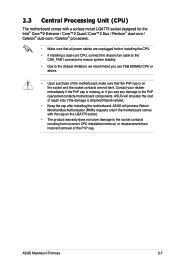
...-core / Celeron® dual-core / Celeron® processors. • Make sure that all power cables are not bent. ASUS will shoulder the cost of the PnP cap. ASUS Maximus II Formula 2-7 2.3 Central Processing Unit (CPU) The motherboard comes with the cap on the socket and the socket contacts are unplugged before installing the CPU. • If...
...-core / Celeron® dual-core / Celeron® processors. • Make sure that all power cables are not bent. ASUS will shoulder the cost of the PnP cap. ASUS Maximus II Formula 2-7 2.3 Central Processing Unit (CPU) The motherboard comes with the cap on the socket and the socket contacts are unplugged before installing the CPU. • If...
User Manual
Page 35
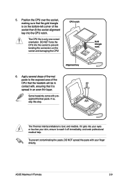
... that the gold triangle is on the socket and damaging the CPU! Apply several drops of thermal paste to wash it is toxic and inedible. ASUS Maximus II Formula 2-9 If so, skip this step. If it gets into the CPU notch. CPU notch Alignment key 6. Position the CPU over the socket, making sure that...
... that the gold triangle is on the socket and damaging the CPU! Apply several drops of thermal paste to wash it is toxic and inedible. ASUS Maximus II Formula 2-9 If so, skip this step. If it gets into the CPU notch. CPU notch Alignment key 6. Position the CPU over the socket, making sure that...
User Manual
Page 37
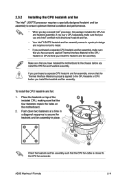
ASUS Maximus II Formula 2-11 If you purchased a separate CPU heatsink and fan assembly, ensure that the Thermal Interface Material is closest to the CPU fan ...requires no tool to install. • If you purchased a separate CPU heatsink and fan assembly, make sure that you have installed the motherboard to the chassis before you install the CPU fan and heatsink assembly. Make sure that you have properly applied Thermal Interface Material to the CPU... assembly. Place the heatsink on top of the installed CPU, making sure that the four fasteners match the holes on the motherboard.
ASUS Maximus II Formula 2-11 If you purchased a separate CPU heatsink and fan assembly, ensure that the Thermal Interface Material is closest to the CPU fan ...requires no tool to install. • If you purchased a separate CPU heatsink and fan assembly, make sure that you have installed the motherboard to the chassis before you install the CPU fan and heatsink assembly. Make sure that you have properly applied Thermal Interface Material to the CPU... assembly. Place the heatsink on top of the installed CPU, making sure that the four fasteners match the holes on the motherboard.
User Manual
Page 39
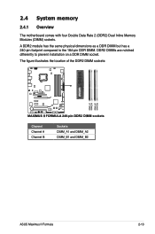
A DDR2 module has the same physical dimensions as a DDR DIMM but has a 240-pin footprint compared to prevent installation on a DDR DIMM socket. 2.4 System memory 2.4.1 Overview The motherboard comes with four Double Data Rate 2 (DDR2) Dual Inline Memory Modules (DIMM) sockets. DDR2 DIMMs are notched differently to the 184-pin DDR DIMM. The figure illustrates the location of the DDR2 DIMM sockets: Channel Channel A Channel B Sockets DIMM_A1 and DIMM_A2 DIMM_B1 and DIMM_B2 ASUS Maximus II Formula 2-13
A DDR2 module has the same physical dimensions as a DDR DIMM but has a 240-pin footprint compared to prevent installation on a DDR DIMM socket. 2.4 System memory 2.4.1 Overview The motherboard comes with four Double Data Rate 2 (DDR2) Dual Inline Memory Modules (DIMM) sockets. DDR2 DIMMs are notched differently to the 184-pin DDR DIMM. The figure illustrates the location of the DDR2 DIMM sockets: Channel Channel A Channel B Sockets DIMM_A1 and DIMM_A2 DIMM_B1 and DIMM_B2 ASUS Maximus II Formula 2-13
User Manual
Page 41
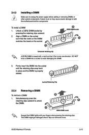
...To remove a DIMM 2 1. Simultaneously press the retaining clips outward to unplug the power supply before adding or removing DIMMs or other system components. ASUS Maximus II Formula 2-15 2.4.3 Installing a DIMM Make sure to unlock 1 the DIMM. 1 DDR2 DIMM notch Support the DIMM lightly with your fingers when pressing ...clips. Unlock a DDR2 DIMM socket by pressing the retaining clips outward. 2. Firmly insert the DIMM into a socket to both the motherboard and the components. Align a DIMM on the socket such that it flips out with a notch so that the notch on the ...
...To remove a DIMM 2 1. Simultaneously press the retaining clips outward to unplug the power supply before adding or removing DIMMs or other system components. ASUS Maximus II Formula 2-15 2.4.3 Installing a DIMM Make sure to unlock 1 the DIMM. 1 DDR2 DIMM notch Support the DIMM lightly with your fingers when pressing ...clips. Unlock a DDR2 DIMM socket by pressing the retaining clips outward. 2. Firmly insert the DIMM into a socket to both the motherboard and the components. Align a DIMM on the socket such that it flips out with a notch so that the notch on the ...
User Manual
Page 43
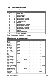
... PCI Steering* 11 6 IRQ Holder for PCI Steering* 12 7 Reserved 13 8 Numeric Data Processor 14 9 Primary IDE Channel * These IRQs are usually available for this motherboard A B C D E F G H PCIE1_1 shared - - - - - - - IRQ assignments for PCI devices. PCIE16_2 shared - - - - - - - PCI_1 shared - - - - - - - shared USB controller ... - - USB controller 3 - - USB controller 4 shared - - - - - - - shared USB 2.0 controller 2 - - SATA controller 1 - - shared - - - - Audio Azalia - - - - - - ASUS Maximus II Formula 2-17
... PCI Steering* 11 6 IRQ Holder for PCI Steering* 12 7 Reserved 13 8 Numeric Data Processor 14 9 Primary IDE Channel * These IRQs are usually available for this motherboard A B C D E F G H PCIE1_1 shared - - - - - - - IRQ assignments for PCI devices. PCIE16_2 shared - - - - - - - PCI_1 shared - - - - - - - shared USB controller ... - - USB controller 3 - - USB controller 4 shared - - - - - - - shared USB 2.0 controller 2 - - SATA controller 1 - - shared - - - - Audio Azalia - - - - - - ASUS Maximus II Formula 2-17
User Manual
Page 45
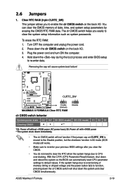
Removing the cap will shut down the clr CMOS switch on the back I /O. ASUS Maximus II Formula 2-19 Hold down and reboot the system so the BIOS can clear the CMOS memory of memory timing or chipset voltage and the power button ...
Removing the cap will shut down the clr CMOS switch on the back I /O. ASUS Maximus II Formula 2-19 Hold down and reboot the system so the BIOS can clear the CMOS memory of memory timing or chipset voltage and the power button ...


