
User Manual
Page 1
M4N68T-M LE Motherboard
M4N68T-M LE Motherboard
User Manual
Page 3
Contents Notices...vi Safety information vii About this guide vii M4N68T-M LE specifications summary ix Chapter 1: Product introduction 1.1 Welcome 1-1 1.2 Package contents 1-1 1.3 Special features 1-1 1.3.1 Product highlights 1-1 1.3.2 Innovative ASUS features 1-3 1.4 Before you proceed 1-5 1.5 Motherboard overview 1-6 1.5.1 Placement direction 1-6 1.5.2 Screw holes 1-6 1.5.3 Motherboard layout 1-7 1.5.4 Layout contents 1-7 1.6 Central Processing Unit (CPU 1-8 1.6.1 Installing the CPU 1-8 1.6.2 Installing the heatsink and fan 1-10 1.7 System memory...
Contents Notices...vi Safety information vii About this guide vii M4N68T-M LE specifications summary ix Chapter 1: Product introduction 1.1 Welcome 1-1 1.2 Package contents 1-1 1.3 Special features 1-1 1.3.1 Product highlights 1-1 1.3.2 Innovative ASUS features 1-3 1.4 Before you proceed 1-5 1.5 Motherboard overview 1-6 1.5.1 Placement direction 1-6 1.5.2 Screw holes 1-6 1.5.3 Motherboard layout 1-7 1.5.4 Layout contents 1-7 1.6 Central Processing Unit (CPU 1-8 1.6.1 Installing the CPU 1-8 1.6.2 Installing the heatsink and fan 1-10 1.7 System memory...
User Manual
Page 6
... which can radiate radio frequency energy and, if not installed and used in accordance with FCC regulations. DO NOT throw the motherboard in our products at ASUS REACH website at http://green.asus.com/english/REACH.htm. This symbol of Chemicals) regulatory framework, we published the chemical substances in municipal waste. If this...
... which can radiate radio frequency energy and, if not installed and used in accordance with FCC regulations. DO NOT throw the motherboard in our products at ASUS REACH website at http://green.asus.com/english/REACH.htm. This symbol of Chemicals) regulatory framework, we published the chemical substances in municipal waste. If this...
User Manual
Page 7
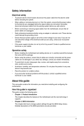
... you are connected. If you are not sure about the voltage of the electrical outlet you need when installing and configuring the motherboard. vii Detailed descriptions of the motherboard and the new technology it by yourself. If you add a device. • Before connecting or removing signal cables from the... motherboard, ensure that all the manuals that came with the product, contact a qualified service technician or your retailer. About this guide is organized ...
... you are connected. If you are not sure about the voltage of the electrical outlet you need when installing and configuring the motherboard. vii Detailed descriptions of the motherboard and the new technology it by yourself. If you add a device. • Before connecting or removing signal cables from the... motherboard, ensure that all the manuals that came with the product, contact a qualified service technician or your retailer. About this guide is organized ...
User Manual
Page 11
... overclocking capabilities with less power consumption. Before you for the following items. Motherboard Cables Accessories Application DVD Documentation ASUS M4N68T-M LE motherboard 2 x Serial ATA cables 1 x Ultra DMA 133/100 cable 1 x I/O shield ASUS motherboard Support DVD User Manual If any of ASUS quality motherboards! Chapter 1 Product introduction 1.1 Welcome! ASUS M4N68T-M LE 1-1 It features dual-channel DDR3 memory support and accelerates data transfer rate...
... overclocking capabilities with less power consumption. Before you for the following items. Motherboard Cables Accessories Application DVD Documentation ASUS M4N68T-M LE motherboard 2 x Serial ATA cables 1 x Ultra DMA 133/100 cable 1 x I/O shield ASUS motherboard Support DVD User Manual If any of ASUS quality motherboards! Chapter 1 Product introduction 1.1 Welcome! ASUS M4N68T-M LE 1-1 It features dual-channel DDR3 memory support and accelerates data transfer rate...

User Manual
Page 12
... features data transfer rates of 1800 (O.C.)/1600 (O.C.)/1333/1066 MHz to your PC! Dual-Channel DDR3 1800 (O.C.) support This motherboard supports DDR3 memory that simultaneously sends different audio streams to provide efficient power management for advanced operating systems. Serial ATA 3Gb/s...on the headphone while playing multi-channel network games. 1-2 Chapter 1: Product introduction AMD® Cool 'n' Quiet Technology This motherboard supports the AMD® Cool 'n' Quiet technology which monitors system operation and automatically adjusts CPU voltage and frequency for Serial...
... features data transfer rates of 1800 (O.C.)/1600 (O.C.)/1333/1066 MHz to your PC! Dual-Channel DDR3 1800 (O.C.) support This motherboard supports DDR3 memory that simultaneously sends different audio streams to provide efficient power management for advanced operating systems. Serial ATA 3Gb/s...on the headphone while playing multi-channel network games. 1-2 Chapter 1: Product introduction AMD® Cool 'n' Quiet Technology This motherboard supports the AMD® Cool 'n' Quiet technology which monitors system operation and automatically adjusts CPU voltage and frequency for Serial...
User Manual
Page 13
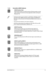
... technology intelligently adjusts the CPU fan speed according to system loading to USB drives only. ASUS M4N68T-M LE 1-3 When installing it on USB HDDs or flash drives, connect the drives to the motherboard USB port before turning on the computer. • The actual boot time depends on SATA ...HDDs, USB HDDs and flash drives with quick access to the Internet and key applications before entering the OS. 1.3.2 Innovative ASUS features ASUS Express Gate ASUS Express Gate is ...
... technology intelligently adjusts the CPU fan speed according to system loading to USB drives only. ASUS M4N68T-M LE 1-3 When installing it on USB HDDs or flash drives, connect the drives to the motherboard USB port before turning on the computer. • The actual boot time depends on SATA ...HDDs, USB HDDs and flash drives with quick access to the Internet and key applications before entering the OS. 1.3.2 Innovative ASUS features ASUS Express Gate ASUS Express Gate is ...

User Manual
Page 14
ASUS EPU ASUS EPU is in real time. C.P.R. feature automatically restores the CPU default settings when the system hangs due to their default settings. Simply shut down and ... the impact on the system and any faulty cable connections are reported back up to open the system chassis and clear the RTC data. ASUS AI NET2 ASUS AI NET2 remotely detects the cable connection immediately after you turn on the environment. 1-4 Chapter 1: Product introduction eliminates the need to 100 meters at...
ASUS EPU ASUS EPU is in real time. C.P.R. feature automatically restores the CPU default settings when the system hangs due to their default settings. Simply shut down and ... the impact on the system and any faulty cable connections are reported back up to open the system chassis and clear the RTC data. ASUS AI NET2 ASUS AI NET2 remotely detects the cable connection immediately after you turn on the environment. 1-4 Chapter 1: Product introduction eliminates the need to 100 meters at...

User Manual
Page 15
... them due to static electricity. • Hold components by the edges to avoid touching the ICs on them. • Whenever you install or remove any motherboard component. 1.4 Before you proceed Take note of the onboard LED. The illustration below shows the location of the following precautions before you install... is a reminder that the system is ON, in sleep mode, or in the bag that came with a standby power LED that lights up to the motherboard, peripherals, or components. SB_PWR M4N68T-M LE ON OFF Standby Power Powered Off M4N68T-M LE Onboard LED ASUS M4N68T-M LE 1-5
... them due to static electricity. • Hold components by the edges to avoid touching the ICs on them. • Whenever you install or remove any motherboard component. 1.4 Before you proceed Take note of the onboard LED. The illustration below shows the location of the following precautions before you install... is a reminder that the system is ON, in sleep mode, or in the bag that came with a standby power LED that lights up to the motherboard, peripherals, or components. SB_PWR M4N68T-M LE ON OFF Standby Power Powered Off M4N68T-M LE Onboard LED ASUS M4N68T-M LE 1-5

User Manual
Page 16
M4N68T-M LE 1-6 Chapter 1: Product introduction The edge with external ports goes to the chassis. Doing so can damage the motherboard. DO NOT overtighten the screws! Place this side towards the rear of the chassis as indicated in the correct orientation. 1.5 Motherboard overview 1.5.1 Placement direction When installing the motherboard, ensure that you place it into the chassis in the image below. 1.5.2 Screw holes Place six screws into the holes indicated by circles to secure the motherboard to the rear part of the chassis.
M4N68T-M LE 1-6 Chapter 1: Product introduction The edge with external ports goes to the chassis. Doing so can damage the motherboard. DO NOT overtighten the screws! Place this side towards the rear of the chassis as indicated in the correct orientation. 1.5 Motherboard overview 1.5.1 Placement direction When installing the motherboard, ensure that you place it into the chassis in the image below. 1.5.2 Screw holes Place six screws into the holes indicated by circles to secure the motherboard to the rear part of the chassis.
User Manual
Page 17
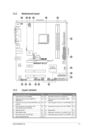
... SATA1-4) 1-24 2. 1.5.3 Motherboard layout 1 23 4 5 6 20.8cm(8.2in) KB/MS KBPWR ATX12V COM1 DDR3 DIMM_A1 (64bit, 240-pin module) DDR3 DIMM_B1 (64bit, 240-pin module) PRI_IDE SOCKET AM3 VGA LPT 7 USBPW1-4 USB34 24.4cm(9.6in) LAN1_USB12 Super I/O CPU_FAN EATXPWR Lithium Cell 3 AUDIO CMOS Power CHA_FAN RTL 8211CL PCIEX16 M4N68T-M LE PCIEX1_1 PCI1 NVIDIA... (10-1 pin USB56, USB78, 1-26 USB910) 3. Onboard LED 1-5 6. System panel connector (10-1 pin F_PANEL) 1-25 5. DDR3 DIMM sockets 1-11 14. Clear RTC RAM (CLRTC) 1-18 ASUS M4N68T-M LE 1-7
... SATA1-4) 1-24 2. 1.5.3 Motherboard layout 1 23 4 5 6 20.8cm(8.2in) KB/MS KBPWR ATX12V COM1 DDR3 DIMM_A1 (64bit, 240-pin module) DDR3 DIMM_B1 (64bit, 240-pin module) PRI_IDE SOCKET AM3 VGA LPT 7 USBPW1-4 USB34 24.4cm(9.6in) LAN1_USB12 Super I/O CPU_FAN EATXPWR Lithium Cell 3 AUDIO CMOS Power CHA_FAN RTL 8211CL PCIEX16 M4N68T-M LE PCIEX1_1 PCI1 NVIDIA... (10-1 pin USB56, USB78, 1-26 USB910) 3. Onboard LED 1-5 6. System panel connector (10-1 pin F_PANEL) 1-25 5. DDR3 DIMM sockets 1-11 14. Clear RTC RAM (CLRTC) 1-18 ASUS M4N68T-M LE 1-7
User Manual
Page 18
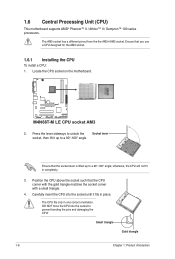
... place. Ensure that the socket lever is lifted up to prevent bending the pins and damaging the CPU! M4N68T-M LE M4N68T-M LE CPU socket AM3 2. Small triangle Gold triangle 1-8 Chapter 1: Product introduction 1.6 Central Processing Unit (CPU) This motherboard supports AMD® Phenom™ II / Athlon™ II / Sempron™ 100 series processors. The CPU fits...
... place. Ensure that the socket lever is lifted up to prevent bending the pins and damaging the CPU! M4N68T-M LE M4N68T-M LE CPU socket AM3 2. Small triangle Gold triangle 1-8 Chapter 1: Product introduction 1.6 Central Processing Unit (CPU) This motherboard supports AMD® Phenom™ II / Athlon™ II / Sempron™ 100 series processors. The CPU fits...
User Manual
Page 19
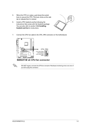
ASUS M4N68T-M LE 1-9 When the CPU is locked. 6. Hardware monitoring errors can also refer to secure the CPU. Install a CPU heatsink and fan following the instructions that it ... fan connector! You can occur if you fail to indicate that comes with the heatsink package. The lever clicks on the motherboard. M4N68T-M LE CPU_FAN CPU FAN PWM CPU FAN IN CPU FAN PWR GND M4N68T-M LE CPU fan connector DO NOT forget to the CPU_FAN connector on the side tab to plug this connector. 5.
ASUS M4N68T-M LE 1-9 When the CPU is locked. 6. Hardware monitoring errors can also refer to secure the CPU. Install a CPU heatsink and fan following the instructions that it ... fan connector! You can occur if you fail to indicate that comes with the heatsink package. The lever clicks on the motherboard. M4N68T-M LE CPU_FAN CPU FAN PWM CPU FAN IN CPU FAN PWR GND M4N68T-M LE CPU fan connector DO NOT forget to the CPU_FAN connector on the side tab to plug this connector. 5.
User Manual
Page 20
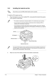
Place the heatsink on top of the retention bracket to remove the retention module base when installing the CPU or installing other motherboard components. • If you purchased a separate CPU heatsink and fan assembly, ensure that you install the heatsink and fan assembly. ...of the installed CPU, ensuring that the heatsink fits properly on the retention module base. • The retention module base is already installed on the motherboard upon purchase. • You do not match the CPU documentation, follow the latter. 2. To install the CPU heatsink and fan: 1. 1.6.2 Installing...
Place the heatsink on top of the retention bracket to remove the retention module base when installing the CPU or installing other motherboard components. • If you purchased a separate CPU heatsink and fan assembly, ensure that you install the heatsink and fan assembly. ...of the installed CPU, ensuring that the heatsink fits properly on the retention module base. • The retention module base is already installed on the motherboard upon purchase. • You do not match the CPU documentation, follow the latter. 2. To install the CPU heatsink and fan: 1. 1.6.2 Installing...
User Manual
Page 21
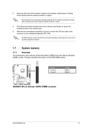
... CPU fan connector! Align the other end of the DDR3 DIMM sockets: DIMM_A1 DIMM_B1 M4N68T-M LE Channel Channel A Channel B M4N68T-M LE 240-pin DDR3 DIMM sockets Sockets DIMM_A1 DIMM_B1 ASUS M4N68T-M LE 1-11 DO NOT forget to plug this connector. 1.7 System memory 1.7.1 Overview The motherboard comes with two Double Data Rate 3 (DDR3) Dual Inline Memory Modules (DIMM) sockets...
... CPU fan connector! Align the other end of the DDR3 DIMM sockets: DIMM_A1 DIMM_B1 M4N68T-M LE Channel Channel A Channel B M4N68T-M LE 240-pin DDR3 DIMM sockets Sockets DIMM_A1 DIMM_B1 ASUS M4N68T-M LE 1-11 DO NOT forget to plug this connector. 1.7 System memory 1.7.1 Overview The motherboard comes with two Double Data Rate 3 (DDR3) Dual Inline Memory Modules (DIMM) sockets...

User Manual
Page 22
... from the higher-sized channel is then mapped for single-channel operation. • Always install DIMMs with the same CAS latency. M4N68T-M LE Motherboard Qualified Vendors Lists (QVL) DDR3-1800(O.C.)MHz capability Vendor Part No. Size SS/DS Brand Chip NO. For effective use of memory...24 • DS N/A Heat-Sink Package 8-8-8-24 •• DS N/A Heat-Sink Package 8-8-8-24 •• continued on the motherboard. • This motherboard does not support DIMMs made up of the lower-sized channel for the OS can be about 3GB or less. The system maps the...
... from the higher-sized channel is then mapped for single-channel operation. • Always install DIMMs with the same CAS latency. M4N68T-M LE Motherboard Qualified Vendors Lists (QVL) DDR3-1800(O.C.)MHz capability Vendor Part No. Size SS/DS Brand Chip NO. For effective use of memory...24 • DS N/A Heat-Sink Package 8-8-8-24 •• DS N/A Heat-Sink Package 8-8-8-24 •• continued on the motherboard. • This motherboard does not support DIMMs made up of the lower-sized channel for the OS can be about 3GB or less. The system maps the...

User Manual
Page 26
... the retaining 1 clips. Failure to do so can cause severe damage to avoid damaging the DIMM. 3. Firmly insert the DIMM into a socket to both the motherboard and the components. 1. Simultaneously press the retaining clips outward to unlock a DIMM socket. 2. 1.7.3 Installing a DIMM Unplug the power supply before adding or removing DIMMs or...
... the retaining 1 clips. Failure to do so can cause severe damage to avoid damaging the DIMM. 3. Firmly insert the DIMM into a socket to both the motherboard and the components. 1. Simultaneously press the retaining clips outward to unlock a DIMM socket. 2. 1.7.3 Installing a DIMM Unplug the power supply before adding or removing DIMMs or...
User Manual
Page 27
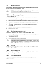
...Keep the screw for the card. 2. See Chapter 2 for the expansion card. When using PCI cards on BIOS setup. 2. ASUS M4N68T-M LE 1-17 Secure the card to use . 4. Before installing the expansion card, read the documentation that the cards do so may need.... 1. Remove the bracket opposite the slot that you intend to the chassis with the PCI Express specifications. 1.8.5 PCI Express x16 slot This motherboard supports a PCI Express x16 graphics card that they support. Replace the system cover. 1.8.2 Configuring an expansion card After installing the expansion card,...
...Keep the screw for the card. 2. See Chapter 2 for the expansion card. When using PCI cards on BIOS setup. 2. ASUS M4N68T-M LE 1-17 Secure the card to use . 4. Before installing the expansion card, read the documentation that the cards do so may need.... 1. Remove the bracket opposite the slot that you intend to the chassis with the PCI Express specifications. 1.8.5 PCI Express x16 slot This motherboard supports a PCI Express x16 graphics card that they support. Replace the system cover. 1.8.2 Configuring an expansion card After installing the expansion card,...
User Manual
Page 31
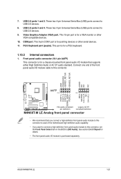
... front panel audio I /O module cable to this connector, set the Front Panel Select item in the BIOS to this connector. Connect one end of the motherboard high-definition audio capability. • If you want to connect a high definition front panel audio module to [HD Audio]. This 15-pin port is purchased... Bus (USB) ports connect to USB 2.0 devices. 8. Front panel audio connector (10-1 pin AAFP) This connector is for a VGA monitor or other serial devices. 11. ASUS M4N68T-M LE 1-21
... front panel audio I /O module cable to this connector, set the Front Panel Select item in the BIOS to this connector. Connect one end of the motherboard high-definition audio capability. • If you want to connect a high definition front panel audio module to [HD Audio]. This 15-pin port is purchased... Bus (USB) ports connect to USB 2.0 devices. 8. Front panel audio connector (10-1 pin AAFP) This connector is for a VGA monitor or other serial devices. 11. ASUS M4N68T-M LE 1-21
User Manual
Page 33
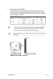
PRI_IDE M4N68T-M LE PIN1 NOTE:Orient the red markings on each Ultra DMA 133/100 signal cable: blue, black, and gray. Master Slave Master Slave Cable connector Black ... to PIN 1. Connect the blue connector to the motherboard's IDE connector, then select one of the following modes to match the covered hole on the IDE connector is set as "Cable-Select", ensure that all other device jumpers have the same setting. M4N68T-M LE IDE connector ASUS M4N68T-M LE 1-23 3. IDE connector (40-1 pin PRI_IDE) The...
PRI_IDE M4N68T-M LE PIN1 NOTE:Orient the red markings on each Ultra DMA 133/100 signal cable: blue, black, and gray. Master Slave Master Slave Cable connector Black ... to PIN 1. Connect the blue connector to the motherboard's IDE connector, then select one of the following modes to match the covered hole on the IDE connector is set as "Cable-Select", ensure that all other device jumpers have the same setting. M4N68T-M LE IDE connector ASUS M4N68T-M LE 1-23 3. IDE connector (40-1 pin PRI_IDE) The...


