User Manual
Page 11
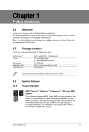
Before you for the following items. Motherboard Cables Accessories Application DVD Documentation ASUS M4N68T-M LE motherboard 2 x Serial ATA cables 1 x Ultra DMA 133/100 cable 1 x I/O shield ASUS motherboard Support DVD User Manual If any of the above items is damaged or missing, contact your retailer. ...1.0-based system bus. This motherboard also supports AMD® CPUs in your motherboard package for buying an ASUS® M4N68T-M LE motherboard! The motherboard delivers a host of ASUS quality motherboards! ASUS M4N68T-M LE 1-1 Chapter 1 Product introduction 1.1 Welcome!
Before you for the following items. Motherboard Cables Accessories Application DVD Documentation ASUS M4N68T-M LE motherboard 2 x Serial ATA cables 1 x Ultra DMA 133/100 cable 1 x I/O shield ASUS motherboard Support DVD User Manual If any of the above items is damaged or missing, contact your retailer. ...1.0-based system bus. This motherboard also supports AMD® CPUs in your motherboard package for buying an ASUS® M4N68T-M LE motherboard! The motherboard delivers a host of ASUS quality motherboards! ASUS M4N68T-M LE 1-1 Chapter 1 Product introduction 1.1 Welcome!
User Manual
Page 13
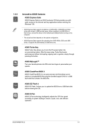
...-color boot logos to ensure a quiet, cool, and efficient operation. ASUS MyLogo2™ Turn your favorite photos into an overclocking button. ASUS Q-Fan ASUS Q-Fan technology intelligently adjusts the CPU fan speed according to system loading to personalize your system. ASUS M4N68T-M LE 1-3 ASUS Turbo Key ASUS Turbo Key allows you to update the BIOS from SATA HDDs...
...-color boot logos to ensure a quiet, cool, and efficient operation. ASUS MyLogo2™ Turn your favorite photos into an overclocking button. ASUS Q-Fan ASUS Q-Fan technology intelligently adjusts the CPU fan speed according to system loading to personalize your system. ASUS M4N68T-M LE 1-3 ASUS Turbo Key ASUS Turbo Key allows you to update the BIOS from SATA HDDs...

User Manual
Page 15
... OFF Standby Power Powered Off M4N68T-M LE Onboard LED ASUS M4N68T-M LE 1-5 1.4 Before you proceed Take note of the onboard LED. The illustration below shows the location of the following precautions before you install motherboard components or ...
... OFF Standby Power Powered Off M4N68T-M LE Onboard LED ASUS M4N68T-M LE 1-5 1.4 Before you proceed Take note of the onboard LED. The illustration below shows the location of the following precautions before you install motherboard components or ...
User Manual
Page 17
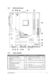
..., USB78, 1-26 USB910) 3. Internal speaker connector (4- Front panel audio connector (10-1 pin AAFP) 1-21 8. Clear RTC RAM (CLRTC) 1-18 ASUS M4N68T-M LE 1-7 AMD CPU socket 1-8 13. ATX power connectors (24-pin EATXPWR, 4-pin 1-22 11. DDR3 DIMM sockets 1-11 14. System panel connector (...7 USBPW1-4 USB34 24.4cm(9.6in) LAN1_USB12 Super I/O CPU_FAN EATXPWR Lithium Cell 3 AUDIO CMOS Power CHA_FAN RTL 8211CL PCIEX16 M4N68T-M LE PCIEX1_1 PCI1 NVIDIA® MCP68 SE 8Mb BIOS 8 CLRTC 2 SATA2 SATA4 PCI2 VIA VT1708S SB_PWR F_PANEL USB56 USB78 USB910 ...
..., USB78, 1-26 USB910) 3. Internal speaker connector (4- Front panel audio connector (10-1 pin AAFP) 1-21 8. Clear RTC RAM (CLRTC) 1-18 ASUS M4N68T-M LE 1-7 AMD CPU socket 1-8 13. ATX power connectors (24-pin EATXPWR, 4-pin 1-22 11. DDR3 DIMM sockets 1-11 14. System panel connector (...7 USBPW1-4 USB34 24.4cm(9.6in) LAN1_USB12 Super I/O CPU_FAN EATXPWR Lithium Cell 3 AUDIO CMOS Power CHA_FAN RTL 8211CL PCIEX16 M4N68T-M LE PCIEX1_1 PCI1 NVIDIA® MCP68 SE 8Mb BIOS 8 CLRTC 2 SATA2 SATA4 PCI2 VIA VT1708S SB_PWR F_PANEL USB56 USB78 USB910 ...
User Manual
Page 19
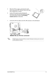
... CPU fan cable to the CPU_FAN connector on the side tab to secure the CPU. M4N68T-M LE CPU_FAN CPU FAN PWM CPU FAN IN CPU FAN PWR GND M4N68T-M LE CPU fan connector DO NOT forget to plug this connector. ASUS M4N68T-M LE 1-9 When the CPU is locked. 6. Install a CPU heatsink and fan following the instructions that...
... CPU fan cable to the CPU_FAN connector on the side tab to secure the CPU. M4N68T-M LE CPU_FAN CPU FAN PWM CPU FAN IN CPU FAN PWR GND M4N68T-M LE CPU fan connector DO NOT forget to plug this connector. ASUS M4N68T-M LE 1-9 When the CPU is locked. 6. Install a CPU heatsink and fan following the instructions that...
User Manual
Page 21
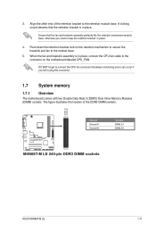
.... Hardware monitoring errors can occur if you cannot snap the retention bracket in place. Align the other end of the DDR3 DIMM sockets: DIMM_A1 DIMM_B1 M4N68T-M LE Channel Channel A Channel B M4N68T-M LE 240-pin DDR3 DIMM sockets Sockets DIMM_A1 DIMM_B1 ASUS M4N68T-M LE 1-11 3.
.... Hardware monitoring errors can occur if you cannot snap the retention bracket in place. Align the other end of the DDR3 DIMM sockets: DIMM_A1 DIMM_B1 M4N68T-M LE Channel Channel A Channel B M4N68T-M LE 240-pin DDR3 DIMM sockets Sockets DIMM_A1 DIMM_B1 ASUS M4N68T-M LE 1-11 3.
User Manual
Page 25
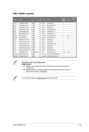
Size SS/ DS Brand Chip NO. ASUS M4N68T-M LE 1-15 Visit the ASUS website at www.asus.com for the latest QVL. Crucial CT12864BA1067.8FF 1024MB SS Crucial CT12872BA1067.9FF 1024MB SS Crucial CT25664BA1067.16FF 2048MB DS Crucial CT25672BA1067.18FF 2048MB DS ...
Size SS/ DS Brand Chip NO. ASUS M4N68T-M LE 1-15 Visit the ASUS website at www.asus.com for the latest QVL. Crucial CT12864BA1067.8FF 1024MB SS Crucial CT12872BA1067.9FF 1024MB SS Crucial CT25664BA1067.16FF 2048MB DS Crucial CT25672BA1067.18FF 2048MB DS ...
User Manual
Page 27
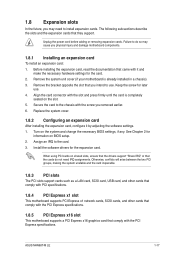
... Express x16 slot This motherboard supports a PCI Express x16 graphics card that came with the screw you removed earlier. 6. Keep the screw for the card. 2. ASUS M4N68T-M LE 1-17 When using PCI cards on the slot. 5. Unplug the power cord before adding or removing expansion cards. Align the card connector with the PCI...
... Express x16 slot This motherboard supports a PCI Express x16 graphics card that came with the screw you removed earlier. 6. Keep the screw for the card. 2. ASUS M4N68T-M LE 1-17 When using PCI cards on the slot. 5. Unplug the power cord before adding or removing expansion cards. Align the card connector with the PCI...
User Manual
Page 29
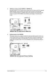
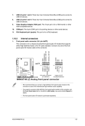
USBPW1-4 12 23 +5V +5VSB (Default) M4N68T-M LE USBPW5-10 12 23 +5V +5VSB (Default) M4N68T-M LE USB Device Wake Up 3. When you set this jumper to wake up the computer from S3 and S4 sleep modes (no power to enable or ... jumper allows you can supply at least 1A on the keyboard (the default is the Space Bar). KBPWR 12 23 +5V +5VSB (Default) M4N68T-M LE M4N68T-M LE Keyboard Power Setting ASUS M4N68T-M LE 1-19 This feature requires an ATX power supply that can wake up the computer from S1 sleep mode (CPU stopped, DRAM refreshed, system running...
USBPW1-4 12 23 +5V +5VSB (Default) M4N68T-M LE USBPW5-10 12 23 +5V +5VSB (Default) M4N68T-M LE USB Device Wake Up 3. When you set this jumper to wake up the computer from S3 and S4 sleep modes (no power to enable or ... jumper allows you can supply at least 1A on the keyboard (the default is the Space Bar). KBPWR 12 23 +5V +5VSB (Default) M4N68T-M LE M4N68T-M LE Keyboard Power Setting ASUS M4N68T-M LE 1-19 This feature requires an ATX power supply that can wake up the computer from S1 sleep mode (CPU stopped, DRAM refreshed, system running...
User Manual
Page 31
... of the motherboard high-definition audio capability. • If you want to connect a high definition front panel audio module to [HD Audio]. ASUS M4N68T-M LE 1-21 USB 2.0 ports 1 and 2. This 15-pin port is for pointing devices or other VGA-compatible devices. 10. Front panel audio ...1 PIN 1 MIC2 MICPWR Line out_R NC Line out_L PORT1 L PORT1 R PORT2 R SENSE_SEND PORT2 L M4N68T-M LE HD-audio-compliant Legacy AC'97 pin definition compliant definition M4N68T-M LE Analog front panel connector • We recommend that supports either High Definition Audio or AC`97 audio standard....
... of the motherboard high-definition audio capability. • If you want to connect a high definition front panel audio module to [HD Audio]. ASUS M4N68T-M LE 1-21 USB 2.0 ports 1 and 2. This 15-pin port is for pointing devices or other VGA-compatible devices. 10. Front panel audio ...1 PIN 1 MIC2 MICPWR Line out_R NC Line out_L PORT1 L PORT1 R PORT2 R SENSE_SEND PORT2 L M4N68T-M LE HD-audio-compliant Legacy AC'97 pin definition compliant definition M4N68T-M LE Analog front panel connector • We recommend that supports either High Definition Audio or AC`97 audio standard....
User Manual
Page 33
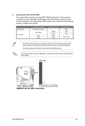
PRI_IDE M4N68T-M LE PIN1 NOTE:Orient the red markings on the IDE connector is set as "Cable-Select", ensure that all other device jumpers have the same setting. 3. ... cable connector. If any device jumper is removed to match the covered hole on each Ultra DMA 133/100 signal cable: blue, black, and gray. M4N68T-M LE IDE connector ASUS M4N68T-M LE 1-23 IDE connector (40-1 pin PRI_IDE) The onboard IDE connector is for Ultra DMA 133/100 IDE devices.
PRI_IDE M4N68T-M LE PIN1 NOTE:Orient the red markings on the IDE connector is set as "Cable-Select", ensure that all other device jumpers have the same setting. 3. ... cable connector. If any device jumper is removed to match the covered hole on each Ultra DMA 133/100 signal cable: blue, black, and gray. M4N68T-M LE IDE connector ASUS M4N68T-M LE 1-23 IDE connector (40-1 pin PRI_IDE) The onboard IDE connector is for Ultra DMA 133/100 IDE devices.
User Manual
Page 35
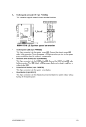
... panel connector • System power LED (2-pin PWRLED) This 2-pin connector is for the HDD Activity LED. PLED+ PLEDPWR GND IDE_LED+ IDE_LED- Ground Reset 6. ASUS M4N68T-M LE 1-25 System panel connector (10-1 pin F_PANEL) This connector supports several chassis-mounted functions. The system power LED lights up or flashes when data is ...
... panel connector • System power LED (2-pin PWRLED) This 2-pin connector is for the HDD Activity LED. PLED+ PLEDPWR GND IDE_LED+ IDE_LED- Ground Reset 6. ASUS M4N68T-M LE 1-25 System panel connector (10-1 pin F_PANEL) This connector supports several chassis-mounted functions. The system power LED lights up or flashes when data is ...

User Manual
Page 37
...! CPU and chassis fan connectors (4-pin CPU_FAN and 3-pin CHA_FAN) Connect the fan cables to the fan connectors on the fan connectors. ASUS M4N68T-M LE 1-27 DO NOT place jumper caps on the motherboard, ensuring that the audio device of the connector. CPU_FAN CPU FAN PWM CPU FAN ...IN CPU FAN PWR GND M4N68T-M LE CHA_FAN Rotation +12V GND M4N68T-M LE fan connectors DO NOT forget to connect the fan cables to configure the setting. 8. Only the 4-pin CPU fan connector supports the ASUS Q-Fan feature. Insufficient air flow inside the system may be...
...! CPU and chassis fan connectors (4-pin CPU_FAN and 3-pin CHA_FAN) Connect the fan cables to the fan connectors on the fan connectors. ASUS M4N68T-M LE 1-27 DO NOT place jumper caps on the motherboard, ensuring that the audio device of the connector. CPU_FAN CPU FAN PWM CPU FAN ...IN CPU FAN PWR GND M4N68T-M LE CHA_FAN Rotation +12V GND M4N68T-M LE fan connectors DO NOT forget to connect the fan cables to configure the setting. 8. Only the 4-pin CPU fan connector supports the ASUS Q-Fan feature. Insufficient air flow inside the system may be...
User Manual
Page 39
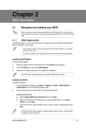
..., then click Next. Always update the utility to download then click Next. Click the Utilities tab, then click ASUS Update. 3. c. From the Windows® desktop, click Start > Programs > ASUS > ASUS Update > ASUS Update to complete the installation. ASUS M4N68T-M LE 2-1 The Drivers menu appears. 2. b. From the FTP site, select the BIOS version that comes with the motherboard...
..., then click Next. Always update the utility to download then click Next. Click the Utilities tab, then click ASUS Update. 3. c. From the Windows® desktop, click Start > Programs > ASUS > ASUS Update > ASUS Update to complete the installation. ASUS M4N68T-M LE 2-1 The Drivers menu appears. 2. b. From the FTP site, select the BIOS version that comes with the motherboard...
User Manual
Page 41
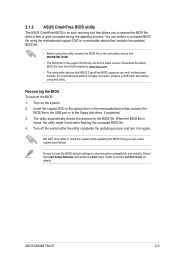
...DVD or a removable device that allows you to restore the BIOS file when it fails or gets corrupted during the updating process. ASUS M4N68T-M LE 2-3 Turn on again. Turn off the system after the utility completes the updating process and turn it on the system. 2. Ensure...under the Exit menu. Recovering the BIOS To recover the BIOS: 1. Refer to the floppy disk drive, if supported. 3. 2.1.3 ASUS CrashFree BIOS utility The ASUS CrashFree BIOS is found, the utility reads it and starts flashing the corrupted BIOS file. 4. For motherboards without a floppy connector, ...
...DVD or a removable device that allows you to restore the BIOS file when it fails or gets corrupted during the updating process. ASUS M4N68T-M LE 2-3 Turn on again. Turn off the system after the utility completes the updating process and turn it on the system. 2. Ensure...under the Exit menu. Recovering the BIOS To recover the BIOS: 1. Refer to the floppy disk drive, if supported. 3. 2.1.3 ASUS CrashFree BIOS utility The ASUS CrashFree BIOS is found, the utility reads it and starts flashing the corrupted BIOS file. 4. For motherboards without a floppy connector, ...

User Manual
Page 43
... At the bottom right corner of a menu screen are the navigation keys for special functions Exit For selecting the exit options and loading default settings. ASUS M4N68T-M LE 2-5 Use the navigation keys to another. Some of the screen has the following main items: Main For changing the basic system configuration Advanced For changing...
... At the bottom right corner of a menu screen are the navigation keys for special functions Exit For selecting the exit options and loading default settings. ASUS M4N68T-M LE 2-5 Use the navigation keys to another. Some of the screen has the following main items: Main For changing the basic system configuration Advanced For changing...
User Manual
Page 45
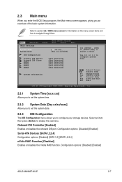
... function. Onboard IDE Controller [Enabled] Enables or disables the onboard IDE port. Select an item then press to navigate through them. Configuration options: [Disabled] [Enabled] ASUS M4N68T-M LE 2-7 2.3 Main menu When you enter the BIOS Setup program, the Main menu screen appears, giving you to configure your storage devices. Select Screen Select Item +-
... function. Onboard IDE Controller [Enabled] Enables or disables the onboard IDE port. Select an item then press to navigate through them. Configuration options: [Disabled] [Enabled] ASUS M4N68T-M LE 2-7 2.3 Main menu When you enter the BIOS Setup program, the Main menu screen appears, giving you to configure your storage devices. Select Screen Select Item +-
User Manual
Page 47
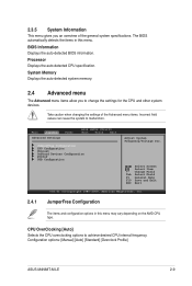
... for the CPU and other system devices. Take caution when changing the settings of the general system specifications. Configuration options: [Manual] [Auto] [Standard] [Overclock Profile] ASUS M4N68T-M LE 2-9 Change Field Tab Select Field F1 General Help F10 Save and Exit ESC Exit v02.61 (C)Copyright 1985-2009, American Megatrends, Inc. 2.4.1 JumperFree Configuration The...
... for the CPU and other system devices. Take caution when changing the settings of the general system specifications. Configuration options: [Manual] [Auto] [Standard] [Overclock Profile] ASUS M4N68T-M LE 2-9 Change Field Tab Select Field F1 General Help F10 Save and Exit ESC Exit v02.61 (C)Copyright 1985-2009, American Megatrends, Inc. 2.4.1 JumperFree Configuration The...
User Manual
Page 49
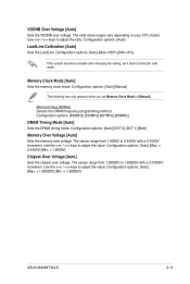
... Value [400MHz] Selects the DRAM frequency programming method. The values range from 1.5000V to [Auto] for safe mode. Configuration options: [Auto] [Max. = 1.60000V] [Min. = 1.20000V] ASUS M4N68T-M LE 2-11 The valid value ranges vary depending on your CPU model. Memory Clock Mode [Auto] Sets the memory clock mode. The values range from 1.20000V...
... Value [400MHz] Selects the DRAM frequency programming method. The values range from 1.5000V to [Auto] for safe mode. Configuration options: [Auto] [Max. = 1.60000V] [Min. = 1.20000V] ASUS M4N68T-M LE 2-11 The valid value ranges vary depending on your CPU model. Memory Clock Mode [Auto] Sets the memory clock mode. The values range from 1.20000V...
User Manual
Page 51
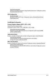
... options: [Auto] [Disabled] Front Panel Select [HD Audio] This item appears only when the Azalia Audio item is set to [Auto]. Configuration options: [Disabled] [Enabled] ASUS M4N68T-M LE 2-13 Configuration options: [Disabled] [IC] [DC] [Enabled] ECC Configuration ECC Mode [Disabled] Allows you to enable or disable the Page Smashing Mechanism.
... options: [Auto] [Disabled] Front Panel Select [HD Audio] This item appears only when the Azalia Audio item is set to [Auto]. Configuration options: [Disabled] [Enabled] ASUS M4N68T-M LE 2-13 Configuration options: [Disabled] [IC] [DC] [Enabled] ECC Configuration ECC Mode [Disabled] Allows you to enable or disable the Page Smashing Mechanism.


