User Manual
Page 11
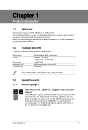
... you for the following items. Motherboard Cables Accessories Application DVD Documentation ASUS M4N68T-M LE motherboard 2 x Serial ATA cables 1 x Ultra DMA 133/100 cable 1 x I/O shield ASUS motherboard Support DVD User Manual If any of ASUS quality motherboards! This motherboard also supports AMD® CPUs in the... long line of the above items is damaged or missing, contact your motherboard package for buying an ASUS® M4N68T-M LE motherboard! Thank you start installing the motherboard, and hardware devices on it another standout in the new 45nm manufacturing ...
... you for the following items. Motherboard Cables Accessories Application DVD Documentation ASUS M4N68T-M LE motherboard 2 x Serial ATA cables 1 x Ultra DMA 133/100 cable 1 x I/O shield ASUS motherboard Support DVD User Manual If any of ASUS quality motherboards! This motherboard also supports AMD® CPUs in the... long line of the above items is damaged or missing, contact your motherboard package for buying an ASUS® M4N68T-M LE motherboard! Thank you start installing the motherboard, and hardware devices on it another standout in the new 45nm manufacturing ...
User Manual
Page 13
... Gate supports file uploading from SATA HDDs, ODDs and USB drives. ASUS Turbo Key ASUS Turbo Key allows you to USB drives only. ASUS CrashFree BIOS 3 ASUS CrashFree BIOS 3 is an ASUS exclusive OS that contains the BIOS file. ASUS M4N68T-M LE 1-3 1.3.2 Innovative ASUS features ASUS Express Gate ASUS Express Gate is an auto-recovery tool that allows you to restore...
... Gate supports file uploading from SATA HDDs, ODDs and USB drives. ASUS Turbo Key ASUS Turbo Key allows you to USB drives only. ASUS CrashFree BIOS 3 ASUS CrashFree BIOS 3 is an ASUS exclusive OS that contains the BIOS file. ASUS M4N68T-M LE 1-3 1.3.2 Innovative ASUS features ASUS Express Gate ASUS Express Gate is an auto-recovery tool that allows you to restore...

User Manual
Page 15
... up to the motherboard, peripherals, or components. This is ON, in sleep mode, or in any component, switch off mode. SB_PWR M4N68T-M LE ON OFF Standby Power Powered Off M4N68T-M LE Onboard LED ASUS M4N68T-M LE 1-5 1.4 Before you proceed Take note of the onboard LED. Onboard LED The motherboard comes with the component. • Before you should...
... up to the motherboard, peripherals, or components. This is ON, in sleep mode, or in any component, switch off mode. SB_PWR M4N68T-M LE ON OFF Standby Power Powered Off M4N68T-M LE Onboard LED ASUS M4N68T-M LE 1-5 1.4 Before you proceed Take note of the onboard LED. Onboard LED The motherboard comes with the component. • Before you should...
User Manual
Page 17
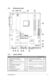
... Front panel audio connector (10-1 pin AAFP) 1-21 8. System panel connector (10-1 pin F_PANEL) 1-25 5. Clear RTC RAM (CLRTC) 1-18 ASUS M4N68T-M LE 1-7 DDR3 DIMM sockets 1-11 14. Serial ATA connectors (7-pin SATA1-4) 1-24 2. Internal speaker connector (4- 1.5.3 Motherboard layout 1 23 4 5 6 ...USBPW1-4 USB34 24.4cm(9.6in) LAN1_USB12 Super I/O CPU_FAN EATXPWR Lithium Cell 3 AUDIO CMOS Power CHA_FAN RTL 8211CL PCIEX16 M4N68T-M LE PCIEX1_1 PCI1 NVIDIA® MCP68 SE 8Mb BIOS 8 CLRTC 2 SATA2 SATA4 PCI2 VIA VT1708S SB_PWR F_PANEL USB56 USB78 ...
... Front panel audio connector (10-1 pin AAFP) 1-21 8. System panel connector (10-1 pin F_PANEL) 1-25 5. Clear RTC RAM (CLRTC) 1-18 ASUS M4N68T-M LE 1-7 DDR3 DIMM sockets 1-11 14. Serial ATA connectors (7-pin SATA1-4) 1-24 2. Internal speaker connector (4- 1.5.3 Motherboard layout 1 23 4 5 6 ...USBPW1-4 USB34 24.4cm(9.6in) LAN1_USB12 Super I/O CPU_FAN EATXPWR Lithium Cell 3 AUDIO CMOS Power CHA_FAN RTL 8211CL PCIEX16 M4N68T-M LE PCIEX1_1 PCI1 NVIDIA® MCP68 SE 8Mb BIOS 8 CLRTC 2 SATA2 SATA4 PCI2 VIA VT1708S SB_PWR F_PANEL USB56 USB78 ...
User Manual
Page 19
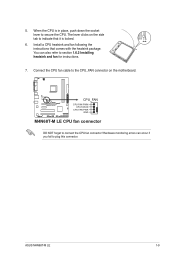
... refer to section 1.6.2 Installing heatsink and fan for instructions. 7. You can occur if you fail to secure the CPU. M4N68T-M LE CPU_FAN CPU FAN PWM CPU FAN IN CPU FAN PWR GND M4N68T-M LE CPU fan connector DO NOT forget to indicate that comes with the heatsink package. Install a CPU heatsink and fan following... connector. Connect the CPU fan cable to the CPU_FAN connector on the side tab to connect the CPU fan connector! When the CPU is locked. 6. ASUS M4N68T-M LE 1-9 5.
... refer to section 1.6.2 Installing heatsink and fan for instructions. 7. You can occur if you fail to secure the CPU. M4N68T-M LE CPU_FAN CPU FAN PWM CPU FAN IN CPU FAN PWR GND M4N68T-M LE CPU fan connector DO NOT forget to indicate that comes with the heatsink package. Install a CPU heatsink and fan following... connector. Connect the CPU fan cable to the CPU_FAN connector on the side tab to connect the CPU fan connector! When the CPU is locked. 6. ASUS M4N68T-M LE 1-9 5.
User Manual
Page 21
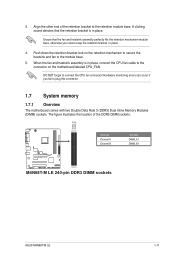
...) Dual Inline Memory Modules (DIMM) sockets. Ensure that the retention bracket is in place. Align the other end of the DDR3 DIMM sockets: DIMM_A1 DIMM_B1 M4N68T-M LE Channel Channel A Channel B M4N68T-M LE 240-pin DDR3 DIMM sockets Sockets DIMM_A1 DIMM_B1 ASUS M4N68T-M LE 1-11
...) Dual Inline Memory Modules (DIMM) sockets. Ensure that the retention bracket is in place. Align the other end of the DDR3 DIMM sockets: DIMM_A1 DIMM_B1 M4N68T-M LE Channel Channel A Channel B M4N68T-M LE 240-pin DDR3 DIMM sockets Sockets DIMM_A1 DIMM_B1 ASUS M4N68T-M LE 1-11
User Manual
Page 25
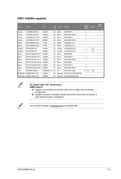
Visit the ASUS website at www.asus.com for the latest QVL. ASUS M4N68T-M LE 1-15 Crucial CT12864BA1067.8FF 1024MB SS Crucial CT12872BA1067.9FF 1024MB SS Crucial CT25664BA1067.16FF 2048MB DS Crucial CT25672BA1067.18FF 2048MB DS Elpida EBJ51UD8BAFA-AC-E 512MB ...
Visit the ASUS website at www.asus.com for the latest QVL. ASUS M4N68T-M LE 1-15 Crucial CT12864BA1067.8FF 1024MB SS Crucial CT12872BA1067.9FF 1024MB SS Crucial CT25664BA1067.16FF 2048MB DS Crucial CT25672BA1067.18FF 2048MB DS Elpida EBJ51UD8BAFA-AC-E 512MB ...
User Manual
Page 27
... the PCI Express specifications. 1.8.5 PCI Express x16 slot This motherboard supports a PCI Express x16 graphics card that comply with it by adjusting the software settings. 1. ASUS M4N68T-M LE 1-17 Unplug the power cord before adding or removing expansion cards. 1.8 Expansion slots In the future, you may cause you physical injury and damage motherboard...
... the PCI Express specifications. 1.8.5 PCI Express x16 slot This motherboard supports a PCI Express x16 graphics card that comply with it by adjusting the software settings. 1. ASUS M4N68T-M LE 1-17 Unplug the power cord before adding or removing expansion cards. 1.8 Expansion slots In the future, you may cause you physical injury and damage motherboard...
User Manual
Page 29
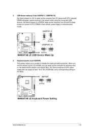
... the +5VSB lead, and a corresponding setting in reduced power mode). KBPWR 12 23 +5V +5VSB (Default) M4N68T-M LE M4N68T-M LE Keyboard Power Setting ASUS M4N68T-M LE 1-19 2. USBPW1-4 12 23 +5V +5VSB (Default) M4N68T-M LE USBPW5-10 12 23 +5V +5VSB (Default) M4N68T-M LE USB Device Wake Up 3. Set these jumpers to +5V to enable or disable the keyboard wake-up...
... the +5VSB lead, and a corresponding setting in reduced power mode). KBPWR 12 23 +5V +5VSB (Default) M4N68T-M LE M4N68T-M LE Keyboard Power Setting ASUS M4N68T-M LE 1-19 2. USBPW1-4 12 23 +5V +5VSB (Default) M4N68T-M LE USBPW5-10 12 23 +5V +5VSB (Default) M4N68T-M LE USB Device Wake Up 3. Set these jumpers to +5V to enable or disable the keyboard wake-up...
User Manual
Page 31
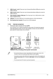
...Serial Bus (USB) ports connect to USB 2.0 devices. 8. This port is for a PS/2 keyboard. 1.10.2 Internal connectors 1. ASUS M4N68T-M LE 1-21 This 9-pin COM1 port is for pointing devices or other VGA-compatible devices. 10. GND PRESENCE# SENSE1_RETUR SENSE2_RETUR AGND NC NC... 1 PIN 1 MIC2 MICPWR Line out_R NC Line out_L PORT1 L PORT1 R PORT2 R SENSE_SEND PORT2 L M4N68T-M LE HD-audio-compliant Legacy AC'97 pin definition compliant definition M4N68T-M LE Analog front panel connector • We recommend that supports either High Definition Audio or AC`97 audio standard....
...Serial Bus (USB) ports connect to USB 2.0 devices. 8. This port is for a PS/2 keyboard. 1.10.2 Internal connectors 1. ASUS M4N68T-M LE 1-21 This 9-pin COM1 port is for pointing devices or other VGA-compatible devices. 10. GND PRESENCE# SENSE1_RETUR SENSE2_RETUR AGND NC NC... 1 PIN 1 MIC2 MICPWR Line out_R NC Line out_L PORT1 L PORT1 R PORT2 R SENSE_SEND PORT2 L M4N68T-M LE HD-audio-compliant Legacy AC'97 pin definition compliant definition M4N68T-M LE Analog front panel connector • We recommend that supports either High Definition Audio or AC`97 audio standard....
User Manual
Page 33
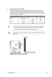
Connect the blue connector to the motherboard's IDE connector, then select one of the following modes to PIN 1. PRI_IDE M4N68T-M LE PIN1 NOTE:Orient the red markings on the IDE ribbon cable to configure your devices: Single device Two devices Drive jumper setting Cable-... on the IDE connector is removed to match the covered hole on each Ultra DMA 133/100 signal cable: blue, black, and gray. M4N68T-M LE IDE connector ASUS M4N68T-M LE 1-23 There are three connectors on the Ultra DMA cable connector. This prevents incorrect insertion when you connect the IDE cable. • Use...
Connect the blue connector to the motherboard's IDE connector, then select one of the following modes to PIN 1. PRI_IDE M4N68T-M LE PIN1 NOTE:Orient the red markings on the IDE ribbon cable to configure your devices: Single device Two devices Drive jumper setting Cable-... on the IDE connector is removed to match the covered hole on each Ultra DMA 133/100 signal cable: blue, black, and gray. M4N68T-M LE IDE connector ASUS M4N68T-M LE 1-23 There are three connectors on the Ultra DMA cable connector. This prevents incorrect insertion when you connect the IDE cable. • Use...
User Manual
Page 35
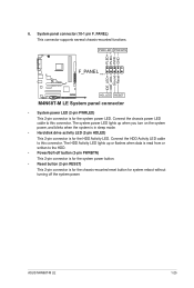
PWR LED PWR BTN F_PANEL PIN 1 M4N68T-M LE HD_LED RESET M4N68T-M LE System panel connector • System power LED (2-pin PWRLED) This 2-pin connector is for system reboot without turning off button (2-pin PWRBTN) This 2-pin connector ... several chassis-mounted functions. Connect the HDD Activity LED cable to the HDD. • Power/Soft-off the system power. PLED+ PLEDPWR GND IDE_LED+ IDE_LED- ASUS M4N68T-M LE 1-25
PWR LED PWR BTN F_PANEL PIN 1 M4N68T-M LE HD_LED RESET M4N68T-M LE System panel connector • System power LED (2-pin PWRLED) This 2-pin connector is for system reboot without turning off button (2-pin PWRBTN) This 2-pin connector ... several chassis-mounted functions. Connect the HDD Activity LED cable to the HDD. • Power/Soft-off the system power. PLED+ PLEDPWR GND IDE_LED+ IDE_LED- ASUS M4N68T-M LE 1-25

User Manual
Page 37
...3-pin CHA_FAN) Connect the fan cables to the fan connectors on the motherboard, ensuring that the audio device of the connector. ASUS M4N68T-M LE 1-27 Insufficient air flow inside the system may be different based on the fan connectors. The S/PDIF module is VIA High ...setting. Only the 4-pin CPU fan connector supports the ASUS Q-Fan feature. Digital audio connector (4-1 pin SPDIF_OUT) This connector is for an additional Sony/Philips Digital Interface (S/PDIF) port. +5V SPDIFOUT GND M4N68T-M LE SPDIF_OUT M4N68T-M LE Digital audio connector Ensure that the black wire of ...
...3-pin CHA_FAN) Connect the fan cables to the fan connectors on the motherboard, ensuring that the audio device of the connector. ASUS M4N68T-M LE 1-27 Insufficient air flow inside the system may be different based on the fan connectors. The S/PDIF module is VIA High ...setting. Only the 4-pin CPU fan connector supports the ASUS Q-Fan feature. Digital audio connector (4-1 pin SPDIF_OUT) This connector is for an additional Sony/Philips Digital Interface (S/PDIF) port. +5V SPDIFOUT GND M4N68T-M LE SPDIF_OUT M4N68T-M LE Digital audio connector Ensure that the black wire of ...
User Manual
Page 39
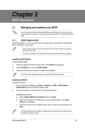
...BIOS using this utility. Quit all its features. b. ASUS M4N68T-M LE 2-1 The Drivers menu appears. 2. Follow the onscreen instructions to launch the ASUS Update utility. 2. From the Windows® desktop, click Start > Programs > ASUS > ASUS Update > ASUS Update to complete the installation. From the dropdown list, ...the Internet. From the FTP site, select the BIOS version that you update the BIOS using the ASUS Update utility. 2.1.1 ASUS Update utility The ASUS Update is a utility that comes with the motherboard package. Select Update BIOS from the Internet a. Click...
...BIOS using this utility. Quit all its features. b. ASUS M4N68T-M LE 2-1 The Drivers menu appears. 2. Follow the onscreen instructions to launch the ASUS Update utility. 2. From the Windows® desktop, click Start > Programs > ASUS > ASUS Update > ASUS Update to complete the installation. From the dropdown list, ...the Internet. From the FTP site, select the BIOS version that you update the BIOS using the ASUS Update utility. 2.1.1 ASUS Update utility The ASUS Update is a utility that comes with the motherboard package. Select Update BIOS from the Internet a. Click...
User Manual
Page 41
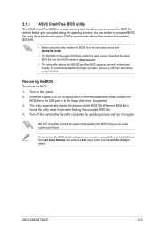
...process and turn it and starts flashing the corrupted BIOS file. 4. ASUS M4N68T-M LE 2-3 The utility automatically checks the devices for details. Turn on again. Download the latest BIOS file from the ASUS website at www.asus.com. • The removable devices that contains the BIOS file ... DVD or a removable device that allows you to the optical drive or the removable device that ASUS CrashFree BIOS supports vary with motherboard models. 2.1.3 ASUS CrashFree BIOS utility The ASUS CrashFree BIOS is found, the utility reads it on the system. 2. You can cause system ...
...process and turn it and starts flashing the corrupted BIOS file. 4. ASUS M4N68T-M LE 2-3 The utility automatically checks the devices for details. Turn on again. Download the latest BIOS file from the ASUS website at www.asus.com. • The removable devices that contains the BIOS file ... DVD or a removable device that allows you to the optical drive or the removable device that ASUS CrashFree BIOS supports vary with motherboard models. 2.1.3 ASUS CrashFree BIOS utility The ASUS CrashFree BIOS is found, the utility reads it on the system. 2. You can cause system ...

User Manual
Page 43
... top of the navigation keys differ from one screen to select items in the menu and change the settings. Use the navigation keys to another. ASUS M4N68T-M LE 2-5
... top of the navigation keys differ from one screen to select items in the menu and change the settings. Use the navigation keys to another. ASUS M4N68T-M LE 2-5
User Manual
Page 45
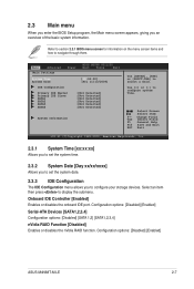
...] [Enabled] Serial-ATA Devices [SATA1,2,3,4] Configuration options: [Disabled] [SATA 1,2] [SATA1,2,3,4] nVidia RAID Function [Disabled] Enables or disables the nVidia RAID function. Configuration options: [Disabled] [Enabled] ASUS M4N68T-M LE 2-7 Main Advanced Main Settings Power BIOS SETUP UTILITY Boot Tools Exit System Time [19:34:30] System Date [Fri 11/13/2009] IDE Configuration Primary...
...] [Enabled] Serial-ATA Devices [SATA1,2,3,4] Configuration options: [Disabled] [SATA 1,2] [SATA1,2,3,4] nVidia RAID Function [Disabled] Enables or disables the nVidia RAID function. Configuration options: [Disabled] [Enabled] ASUS M4N68T-M LE 2-7 Main Advanced Main Settings Power BIOS SETUP UTILITY Boot Tools Exit System Time [19:34:30] System Date [Fri 11/13/2009] IDE Configuration Primary...
User Manual
Page 47
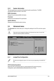
... the system to achieve desired CPU internal frequency. CPU OverClocking [Auto] Selects the CPU overclocking options to malfunction. Configuration options: [Manual] [Auto] [Standard] [Overclock Profile] ASUS M4N68T-M LE 2-9 Processor Displays the auto-detected CPU specification. BIOS Information Displays the auto-detected BIOS information. Change Field Tab Select Field F1 General Help F10 Save...
... the system to achieve desired CPU internal frequency. CPU OverClocking [Auto] Selects the CPU overclocking options to malfunction. Configuration options: [Manual] [Auto] [Standard] [Overclock Profile] ASUS M4N68T-M LE 2-9 Processor Displays the auto-detected CPU specification. BIOS Information Displays the auto-detected BIOS information. Change Field Tab Select Field F1 General Help F10 Save...
User Manual
Page 49
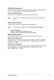
.... Configuration options: [Auto] [Manual] The following item only appears when you set it back to adjust the value. Configuration options: [Auto] [Max. = 1.60000V] [Min. = 1.20000V] ASUS M4N68T-M LE 2-11 Memclock Value [400MHz] Selects the DRAM frequency programming method. Use the / keys to [Manual]. Configuration options: [Auto] [Max. = 2.4450V] [Min. = 1.5000V] Chipset Over Voltage...
.... Configuration options: [Auto] [Manual] The following item only appears when you set it back to adjust the value. Configuration options: [Auto] [Max. = 1.60000V] [Min. = 1.20000V] ASUS M4N68T-M LE 2-11 Memclock Value [400MHz] Selects the DRAM frequency programming method. Use the / keys to [Manual]. Configuration options: [Auto] [Max. = 2.4450V] [Min. = 1.5000V] Chipset Over Voltage...
User Manual
Page 51
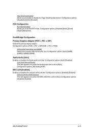
... the primary display adapter. Configuration options: [Auto] [32MB] [64MB] [128MB] [256MB] Azalia Audio [Auto] Enables or disables the Azalia audio controller. Configuration options: [Disabled] [Enabled] ASUS M4N68T-M LE 2-13 Configuration options: [Auto] [Disabled] Front Panel Select [HD Audio] This item appears only when the Azalia Audio item is set to enable or disable...
... the primary display adapter. Configuration options: [Auto] [32MB] [64MB] [128MB] [256MB] Azalia Audio [Auto] Enables or disables the Azalia audio controller. Configuration options: [Disabled] [Enabled] ASUS M4N68T-M LE 2-13 Configuration options: [Auto] [Disabled] Front Panel Select [HD Audio] This item appears only when the Azalia Audio item is set to enable or disable...


