User Manual
Page 19
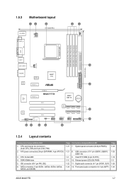
Clear RTC RAM (3-pin CLRTC) 1-11 10. 1.5.3 Motherboard layout 12 3 21.3cm(8.4in) KB_USB56 SPDIF_O ATX12V 4 1 ...30.5cm(12.0in) AUDIO ICS 9LPRS485 AMD® 770 RTL 8112L PCIEX1_1 2 EATXPWR PCIEX1_2 PCIEX16 M4A77TD AMD® SB710 Lithium Cell CMOS Power Super I/O PCI1 PCI2 8Mb BIOS SATA1 SATA2 SATA3 6... pin USB78, USB910, USB1112) 1-8 9. Front panel audio connector (10-1 pin AAFP) Page 1-24 1-25 1-18 1-5 1-26 1-26 ASUS M4A77TD 1-7 CPU Socket AM3 4. Digital audio connector (4-1 pin SPDIF_OUT) 1-23 12. Onboard power LED (SB_PWR) 1-22 11. SATA connectors (7-pin ...
Clear RTC RAM (3-pin CLRTC) 1-11 10. 1.5.3 Motherboard layout 12 3 21.3cm(8.4in) KB_USB56 SPDIF_O ATX12V 4 1 ...30.5cm(12.0in) AUDIO ICS 9LPRS485 AMD® 770 RTL 8112L PCIEX1_1 2 EATXPWR PCIEX1_2 PCIEX16 M4A77TD AMD® SB710 Lithium Cell CMOS Power Super I/O PCI1 PCI2 8Mb BIOS SATA1 SATA2 SATA3 6... pin USB78, USB910, USB1112) 1-8 9. Front panel audio connector (10-1 pin AAFP) Page 1-24 1-25 1-18 1-5 1-26 1-26 ASUS M4A77TD 1-7 CPU Socket AM3 4. Digital audio connector (4-1 pin SPDIF_OUT) 1-23 12. Onboard power LED (SB_PWR) 1-22 11. SATA connectors (7-pin ...

User Manual
Page 30
... 23 Normal (Default) M4A77TD Clear RTC RAM Clear RTC To erase the RTC RAM: 1. Plug the power cord and turn ON the computer. 4. Shut down the key...from pins 1-2 (default) to overclocking, use the CPU Parameter Recall (C.P.R) feature. The onboard button cell battery powers the RAM data in CMOS. Turn OFF the computer and unplug the power cord. 2. Hold down and reboot the system so the...BIOS can clear the CMOS memory of date, time, and system setup parameters by erasing the CMOS RTC RAM data. After clearing the CMOS, reinstall the battery. • You do not help, remove the ...
... 23 Normal (Default) M4A77TD Clear RTC RAM Clear RTC To erase the RTC RAM: 1. Plug the power cord and turn ON the computer. 4. Shut down the key...from pins 1-2 (default) to overclocking, use the CPU Parameter Recall (C.P.R) feature. The onboard button cell battery powers the RAM data in CMOS. Turn OFF the computer and unplug the power cord. 2. Hold down and reboot the system so the...BIOS can clear the CMOS memory of date, time, and system setup parameters by erasing the CMOS RTC RAM data. After clearing the CMOS, reinstall the battery. • You do not help, remove the ...

User Manual
Page 61
... on how to any field. In the password box, key in setting a supervisor password. Confirm the password when prompted. To change to erase the RTC RAM. ASUS M4A77TD 2-21 Full Access allows viewing and changing all the fields in the Setup utility. If you to select the access restriction to the Setup items... to set a Supervisor Password: 1. Select the Change Supervisor Password item and press . 2. After you can clear it by erasing the CMOS Real Time Clock (RTC) RAM.
... on how to any field. In the password box, key in setting a supervisor password. Confirm the password when prompted. To change to erase the RTC RAM. ASUS M4A77TD 2-21 Full Access allows viewing and changing all the fields in the Setup utility. If you to select the access restriction to the Setup items... to set a Supervisor Password: 1. Select the Change Supervisor Password item and press . 2. After you can clear it by erasing the CMOS Real Time Clock (RTC) RAM.
User Manual
Page 64
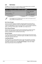
... than System Date, System Time, and Password, the BIOS asks for each of tSheeloepcttionSscfrroementhis menu or from the Exit menu to the non-volatile RAM. 2-24 Chapter 2: BIOS information Select Item Enter Go to Sub-screen F1 General Help F10 Save and Exit Exit & Save Changes ESC Exit... saving the changes. Select OK to load default values. Pressing does not immediately exit this operation. An onboard backup battery sustains the CMOS RAM so it stays on the Setup menus. Select OK to discard any changes and load the previously saved values. Select one of the parameters...
... than System Date, System Time, and Password, the BIOS asks for each of tSheeloepcttionSscfrroementhis menu or from the Exit menu to the non-volatile RAM. 2-24 Chapter 2: BIOS information Select Item Enter Go to Sub-screen F1 General Help F10 Save and Exit Exit & Save Changes ESC Exit... saving the changes. Select OK to load default values. Pressing does not immediately exit this operation. An onboard backup battery sustains the CMOS RAM so it stays on the Setup menus. Select OK to discard any changes and load the previously saved values. Select one of the parameters...


