
User Manual
Page 1
M4A77TD Motherboard
M4A77TD Motherboard

User Manual
Page 3
Contents Notices...vi Safety information vii About this guide viii M4A77TD specifications summary x Chapter 1: Product introduction 1.1 Welcome 1-1 1.2 Package contents 1-1 1.3 Special features 1-1 1.3.1 Product highlights 1-1 1.3.2 Innovative ASUS features 1-3 1.4 Before you proceed 1-5 1.5 Motherboard overview 1-6 1.5.1 Placement direction 1-6 1.5.2 Screw holes 1-6 1.5.3 Motherboard layout 1-7 1.5.4 Layout contents 1-7 1.6 Central Processing Unit (CPU 1-8 1.6.1 Installing the CPU 1-8 1.6.2 Installing the heatsink and fan 1-10 1.7 System memory 1-11...
Contents Notices...vi Safety information vii About this guide viii M4A77TD specifications summary x Chapter 1: Product introduction 1.1 Welcome 1-1 1.2 Package contents 1-1 1.3 Special features 1-1 1.3.1 Product highlights 1-1 1.3.2 Innovative ASUS features 1-3 1.4 Before you proceed 1-5 1.5 Motherboard overview 1-6 1.5.1 Placement direction 1-6 1.5.2 Screw holes 1-6 1.5.3 Motherboard layout 1-7 1.5.4 Layout contents 1-7 1.6 Central Processing Unit (CPU 1-8 1.6.1 Installing the CPU 1-8 1.6.2 Installing the heatsink and fan 1-10 1.7 System memory 1-11...

User Manual
Page 6
..., Evaluation, Authorisation, and Restriction of the crossed out wheeled bin indicates that to provide reasonable protection against harmful interference in our products at ASUS REACH website at http://green.asus.com/english/REACH.htm. However, there is connected. • Consult the dealer or an experienced radio/TV technician for a Class B digital device... out wheeled bin indicates that interference will not occur in the Radio Interference Regulations of the Canadian Department of electronic products. DO NOT throw the motherboard in municipal waste.
..., Evaluation, Authorisation, and Restriction of the crossed out wheeled bin indicates that to provide reasonable protection against harmful interference in our products at ASUS REACH website at http://green.asus.com/english/REACH.htm. However, there is connected. • Consult the dealer or an experienced radio/TV technician for a Class B digital device... out wheeled bin indicates that interference will not occur in the Radio Interference Regulations of the Canadian Department of electronic products. DO NOT throw the motherboard in municipal waste.

User Manual
Page 7
... a qualified service technician or your retailer. • The optical S/PDIF is an optional component (may or may not be included in your motherboard) and is broken, do not try to fix it to a hazardous material collection point. • Never replace the battery with your regular...you are not sure about the voltage of the electrical outlet you add a device. • Before connecting or removing signal cables from the motherboard, ensure that all power cables are unplugged. • Seek professional assistance before the signal cables are connected. These devices could explode and release...
... a qualified service technician or your retailer. • The optical S/PDIF is an optional component (may or may not be included in your motherboard) and is broken, do not try to fix it to a hazardous material collection point. • Never replace the battery with your regular...you are not sure about the voltage of the electrical outlet you add a device. • Before connecting or removing signal cables from the motherboard, ensure that all power cables are unplugged. • Seek professional assistance before the signal cables are connected. These devices could explode and release...

User Manual
Page 8
...parts: • Chapter 1: Product introduction This chapter describes the features of the BIOS parameters are not damaged. Detailed descriptions of the motherboard and the new technology it supports. • Chapter 2: BIOS information This chapter tells how to change system settings through the BIOS Setup... on it, carefully read all the manuals that all cables are correctly connected and the power cables are also provided. This motherboard should only be used in any damage, contact your retailer. How this guide This user guide contains the information you encounter technical...
...parts: • Chapter 1: Product introduction This chapter describes the features of the BIOS parameters are not damaged. Detailed descriptions of the motherboard and the new technology it supports. • Chapter 2: BIOS information This chapter tells how to change system settings through the BIOS Setup... on it, carefully read all the manuals that all cables are correctly connected and the power cables are also provided. This motherboard should only be used in any damage, contact your retailer. How this guide This user guide contains the information you encounter technical...
User Manual
Page 13
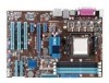
... introduction 1.1 Welcome! Before you for the following items. Motherboard Cables Accessories Application DVD Documentation ASUS M4A77TD motherboard 2 x Serial ATA cables 1 x Ultra DMA 133/100/66 cable 1 x I/O shield ASUS motherboard Support DVD User Manual If any of ASUS quality motherboards! The motherboard delivers a host of new features and latest technologies, making it , check the items in your package with less...
... introduction 1.1 Welcome! Before you for the following items. Motherboard Cables Accessories Application DVD Documentation ASUS M4A77TD motherboard 2 x Serial ATA cables 1 x Ultra DMA 133/100/66 cable 1 x I/O shield ASUS motherboard Support DVD User Manual If any of ASUS quality motherboards! The motherboard delivers a host of new features and latest technologies, making it , check the items in your package with less...

User Manual
Page 14
... bandwidth up to provide excellent system performance and overclocking capabilities. AMD® Cool 'n' Quiet Technology This motherboard supports the AMD® Cool 'n' Quiet technology which makes it an ideal memory solution. DDR3 1800(O.C.) support This motherboard supports DDR3 1800(O.C.)/1600(O.C.)/1333/ 1066MHz memory that features faster data transfer rates and more bandwidth...
... bandwidth up to provide excellent system performance and overclocking capabilities. AMD® Cool 'n' Quiet Technology This motherboard supports the AMD® Cool 'n' Quiet technology which makes it an ideal memory solution. DDR3 1800(O.C.) support This motherboard supports DDR3 1800(O.C.)/1600(O.C.)/1333/ 1066MHz memory that features faster data transfer rates and more bandwidth...
User Manual
Page 15
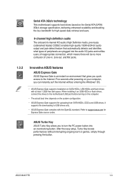
... turning on the computer. • The actual boot time depends on SATA HDDs, USB HDDs and flash drives with the OpenGL standard. ASUS M4A77TD 1-3 Serial ATA 3Gb/s technology This motherboard supports hard drives based on the Serial ATA (SATA) 3Gb/s storage specification, delivering enhanced scalability and doubling the bus bandwidth for Express Gate...
... turning on the computer. • The actual boot time depends on SATA HDDs, USB HDDs and flash drives with the OpenGL standard. ASUS M4A77TD 1-3 Serial ATA 3Gb/s technology This motherboard supports hard drives based on the Serial ATA (SATA) 3Gb/s storage specification, delivering enhanced scalability and doubling the bus bandwidth for Express Gate...

User Manual
Page 16
Green ASUS This motherboard and its packaging comply with the ASUS vision of Hazardous Substances (RoHS). ASUS EPU ASUS EPU is in real time. C.P.R. ASUS Q-Fan ASUS Q-Fan technology intelligently adjusts the CPU fan speed according to system loading to overclocking failure. feature automatically restores ... the BIOS automatically restores the CPU parameters to personalize your favorite photos into 256-color boot logos to their default settings. ASUS EZ Flash 2 ASUS EZ Flash 2 allows you to open the system chassis and clear the RTC data. This is a unique power saving technology...
Green ASUS This motherboard and its packaging comply with the ASUS vision of Hazardous Substances (RoHS). ASUS EPU ASUS EPU is in real time. C.P.R. ASUS Q-Fan ASUS Q-Fan technology intelligently adjusts the CPU fan speed according to system loading to overclocking failure. feature automatically restores ... the BIOS automatically restores the CPU parameters to personalize your favorite photos into 256-color boot logos to their default settings. ASUS EZ Flash 2 ASUS EZ Flash 2 allows you to open the system chassis and clear the RTC data. This is a unique power saving technology...

User Manual
Page 17
... bag that came with a standby power LED that lights up to the motherboard, peripherals, or components. M4A77TD SB_PWR ON OFF Standby Power Powered Off M4A77TD Onboard power LED ASUS M4A77TD 1-5 Onboard LED The motherboard comes with the component. • Before you should shut down the system... and unplug the power cable before removing or plugging in soft-off the ATX power supply and detach its ...
... bag that came with a standby power LED that lights up to the motherboard, peripherals, or components. M4A77TD SB_PWR ON OFF Standby Power Powered Off M4A77TD Onboard power LED ASUS M4A77TD 1-5 Onboard LED The motherboard comes with the component. • Before you should shut down the system... and unplug the power cable before removing or plugging in soft-off the ATX power supply and detach its ...

User Manual
Page 18
Doing so can damage the motherboard. Place this side towards the rear of the chassis as indicated in the image below. 1.5.2 Screw holes Place six screws into the chassis in the correct orientation. M4A77TD 1-6 Chapter 1: Product introduction DO NOT overtighten the screws! The edge with external ports goes to the chassis. 1.5 Motherboard overview 1.5.1 Placement direction When installing the motherboard, ensure that you place it into the holes indicated by circles to secure the motherboard to the rear part of the chassis.
Doing so can damage the motherboard. Place this side towards the rear of the chassis as indicated in the image below. 1.5.2 Screw holes Place six screws into the chassis in the correct orientation. M4A77TD 1-6 Chapter 1: Product introduction DO NOT overtighten the screws! The edge with external ports goes to the chassis. 1.5 Motherboard overview 1.5.1 Placement direction When installing the motherboard, ensure that you place it into the holes indicated by circles to secure the motherboard to the rear part of the chassis.
User Manual
Page 19
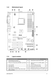
... SATA6) Page Connectors/Jumpers/Slots/LED 1-27 7. Front panel audio connector (10-1 pin AAFP) Page 1-24 1-25 1-18 1-5 1-26 1-26 ASUS M4A77TD 1-7 1.5.3 Motherboard layout 12 3 21.3cm(8.4in) KB_USB56 SPDIF_O ATX12V 4 1 CHA_FAN DDR3 DIMM_A2 (64bit, 240-pin module) DDR3 DIMM_B2 (64bit, 240-pin module)... USB910 PANEL CLRTC 7 12 11 10 9 8 1.5.4 Layout contents Connectors/Jumpers/Slots/LED 1. Clear RTC RAM (3-pin CLRTC) 1-11 10. ATX power connectors (24-pin EATXPWR, 4-pin ATX12V) 3. IDE connector (40-1 pin PRI_IDE) 6. Digital audio connector (4-1 pin SPDIF_OUT) 1-23 12...
... SATA6) Page Connectors/Jumpers/Slots/LED 1-27 7. Front panel audio connector (10-1 pin AAFP) Page 1-24 1-25 1-18 1-5 1-26 1-26 ASUS M4A77TD 1-7 1.5.3 Motherboard layout 12 3 21.3cm(8.4in) KB_USB56 SPDIF_O ATX12V 4 1 CHA_FAN DDR3 DIMM_A2 (64bit, 240-pin module) DDR3 DIMM_B2 (64bit, 240-pin module)... USB910 PANEL CLRTC 7 12 11 10 9 8 1.5.4 Layout contents Connectors/Jumpers/Slots/LED 1. Clear RTC RAM (3-pin CLRTC) 1-11 10. ATX power connectors (24-pin EATXPWR, 4-pin ATX12V) 3. IDE connector (40-1 pin PRI_IDE) 6. Digital audio connector (4-1 pin SPDIF_OUT) 1-23 12...
User Manual
Page 20
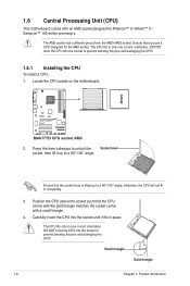
... corner with an AM3 socket designed for the AM3 socket. Small triangle Gold triangle 1-8 Chapter 1: Product introduction 1.6 Central Processing Unit (CPU) This motherboard comes with a small triangle. 4. DO NOT force the CPU into the socket to prevent bending the pins and damaging the CPU! Ensure that you...the CPU! 1.6.1 Installing the CPU To install a CPU: 1. Ensure that the socket lever is lifted up to a 90°-100° angle; M4A77TD M4A77TD CPU socket AM3 2. DO NOT force the CPU into the socket until it up to a 90°-100° angle. The CPU fits in ...
... corner with an AM3 socket designed for the AM3 socket. Small triangle Gold triangle 1-8 Chapter 1: Product introduction 1.6 Central Processing Unit (CPU) This motherboard comes with a small triangle. 4. DO NOT force the CPU into the socket to prevent bending the pins and damaging the CPU! Ensure that you...the CPU! 1.6.1 Installing the CPU To install a CPU: 1. Ensure that the socket lever is lifted up to a 90°-100° angle; M4A77TD M4A77TD CPU socket AM3 2. DO NOT force the CPU into the socket until it up to a 90°-100° angle. The CPU fits in ...
User Manual
Page 21
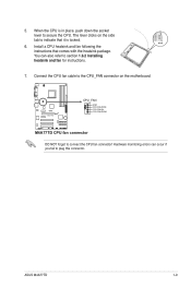
The lever clicks on the motherboard. ASUS M4A77TD 1-9 When the CPU is locked. 6. You can occur if you fail to plug this connector. M4A77TD CPU_FAN GND CPU FAN PWR CPU FAN IN CPU FAN PWM M4A77TD CPU fan connector DO NOT forget to indicate that comes with the heatsink package. Hardware monitoring errors can also refer...
The lever clicks on the motherboard. ASUS M4A77TD 1-9 When the CPU is locked. 6. You can occur if you fail to plug this connector. M4A77TD CPU_FAN GND CPU FAN PWR CPU FAN IN CPU FAN PWM M4A77TD CPU fan connector DO NOT forget to indicate that comes with the heatsink package. Hardware monitoring errors can also refer...

User Manual
Page 22
...retention mechanism. If the instructions in this section do not have to remove the retention module base when installing the CPU or installing other motherboard components. • If you purchased a separate CPU heatsink and fan assembly, ensure that a Thermal Interface Material is properly applied to ...the retention module base. 1 2 3 4 5 1-10 Chapter 1: Product introduction Place the heatsink on the motherboard upon purchase. • You do not match the CPU documentation, follow the latter. 2. Attach one end of the installed CPU, ensuring ...
...retention mechanism. If the instructions in this section do not have to remove the retention module base when installing the CPU or installing other motherboard components. • If you purchased a separate CPU heatsink and fan assembly, ensure that a Thermal Interface Material is properly applied to ...the retention module base. 1 2 3 4 5 1-10 Chapter 1: Product introduction Place the heatsink on the motherboard upon purchase. • You do not match the CPU documentation, follow the latter. 2. Attach one end of the installed CPU, ensuring ...

User Manual
Page 23
... M4A77TD M4A77TD 240-pin DDR3 DIMM sockets ASUS M4A77TD 1-11 DO NOT forget to the module base. 5. A clicking sound denotes that the fan and heatsink assembly perfectly fits the retention mechanism module base, otherwise you fail to plug this connector. 1.7 System memory 1.7.1 Overview This motherboard ... CPU fan cable to the retention module base. The figure illustrates the location of the retention bracket to the connector on the motherboard labeled CPU_FAN. 3. When the fan and heatsink assembly is in place. DDR3 modules are developed for better performance with four Double...
... M4A77TD M4A77TD 240-pin DDR3 DIMM sockets ASUS M4A77TD 1-11 DO NOT forget to the module base. 5. A clicking sound denotes that the fan and heatsink assembly perfectly fits the retention mechanism module base, otherwise you fail to plug this connector. 1.7 System memory 1.7.1 Overview This motherboard ... CPU fan cable to the retention module base. The figure illustrates the location of the retention bracket to the connector on the motherboard labeled CPU_FAN. 3. When the fan and heatsink assembly is in place. DDR3 modules are developed for better performance with four Double...
User Manual
Page 24
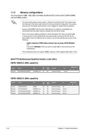
M4A77TD Motherboard Qualified Vendors Lists (QVL) DDR3-1866(O.C.)MHz capability Vendor Part No. Kingston KHX14900D3K3/3GX(XMP) Size SS/ DS Chip Brand Chip NO. 3072MB(kit of 2) ...; Always install DIMMs with the same CAS latency. For effective use of memory, we recommend that you install 4GB or more memory on the motherboard. • This motherboard does not support DIMMs made up of the following: I�n�s�ta�l�l�a��m�a�x�i�m�u�...
M4A77TD Motherboard Qualified Vendors Lists (QVL) DDR3-1866(O.C.)MHz capability Vendor Part No. Kingston KHX14900D3K3/3GX(XMP) Size SS/ DS Chip Brand Chip NO. 3072MB(kit of 2) ...; Always install DIMMs with the same CAS latency. For effective use of memory, we recommend that you install 4GB or more memory on the motherboard. • This motherboard does not support DIMMs made up of the following: I�n�s�ta�l�l�a��m�a�x�i�m�u�...

User Manual
Page 28
... to unlock the DIMM. 2 Support the DIMM lightly with your fingers when pressing the retaining 1 clips. Simultaneously press the retaining clips outward to both the motherboard and the components. 1. Remove the DIMM from the socket. 1-16 Chapter 1: Product introduction Firmly insert the DIMM into a socket to unlock a DIMM socket. 2. DO NOT...
... to unlock the DIMM. 2 Support the DIMM lightly with your fingers when pressing the retaining 1 clips. Simultaneously press the retaining clips outward to both the motherboard and the components. 1. Remove the DIMM from the socket. 1-16 Chapter 1: Product introduction Firmly insert the DIMM into a socket to unlock a DIMM socket. 2. DO NOT...
User Manual
Page 29
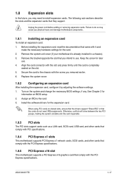
...Keep the screw for the card. 2. Turn on BIOS setup. 2. When using PCI cards on the slot. 5. ASUS M4A77TD 1-17 Remove the system unit cover (if your motherboard is completely seated on shared slots, ensure that the drivers support "Share IRQ" or that comply with the PCI Express.... See Chapter 2 for the expansion card. Align the card connector with the PCI Express specifications. 1.8.5 PCI Express x16 slot This motherboard supports a PCI Express x16 graphics card that the cards do so may need IRQ assignments. Before installing the expansion card, read the...
...Keep the screw for the card. 2. Turn on BIOS setup. 2. When using PCI cards on the slot. 5. ASUS M4A77TD 1-17 Remove the system unit cover (if your motherboard is completely seated on shared slots, ensure that the drivers support "Share IRQ" or that comply with the PCI Express.... See Chapter 2 for the expansion card. Align the card connector with the PCI Express specifications. 1.8.5 PCI Express x16 slot This motherboard supports a PCI Express x16 graphics card that the cards do so may need IRQ assignments. Before installing the expansion card, read the...

User Manual
Page 34
PRI_IDE PIN1 M4A77TD NOTE:Orient the red markings on the Ultra DMA cable connector. Connect the blue connector to the motherboard's IDE connector, then select one of the following modes to PIN 1. If any device jumper is removed to match the covered hole on the IDE...of device(s) - There are three connectors on the IDE connector is set as "Cable-Select", ensure that all other device jumpers have the same setting. M4A77TD IDE connector 1-22 Chapter 1: Product introduction Master Slave Master Slave Cable connector Black Black Gray Black or gray • Pin 20 on each Ultra DMA...
PRI_IDE PIN1 M4A77TD NOTE:Orient the red markings on the Ultra DMA cable connector. Connect the blue connector to the motherboard's IDE connector, then select one of the following modes to PIN 1. If any device jumper is removed to match the covered hole on the IDE...of device(s) - There are three connectors on the IDE connector is set as "Cable-Select", ensure that all other device jumpers have the same setting. M4A77TD IDE connector 1-22 Chapter 1: Product introduction Master Slave Master Slave Cable connector Black Black Gray Black or gray • Pin 20 on each Ultra DMA...


