Motherboard DIY Troubleshooting Guide
Page 3
Contents Notices vi Safety information vii K8V-VM Ultra specifications summary viii Chapter 1: Product Introduction 1.1 Welcome 1-2 1.2 Package contents 1-2 1.3 Special features 1-2 1.3.1 Product highlights 1-2 1.3.2 ASUS unique features 1-4 1.4 Before you proceed 1-5 1.5 Motherboard overview 1-6 1.5.1 Motherboard layout 1-6 1.5.2 Placement direction 1-7 1.5.3 Screw holes 1-7 1.6 Central Processing Unit (CPU 1-8 1.6.1 Overview 1-8 1.6.2 Installing the CPU 1-8 1.7 System memory 1-10 1.7.1 Overview 1-10 1.7.2 Memory configurations 1-10 1.7.3 Installing...
Contents Notices vi Safety information vii K8V-VM Ultra specifications summary viii Chapter 1: Product Introduction 1.1 Welcome 1-2 1.2 Package contents 1-2 1.3 Special features 1-2 1.3.1 Product highlights 1-2 1.3.2 ASUS unique features 1-4 1.4 Before you proceed 1-5 1.5 Motherboard overview 1-6 1.5.1 Motherboard layout 1-6 1.5.2 Placement direction 1-7 1.5.3 Screw holes 1-7 1.6 Central Processing Unit (CPU 1-8 1.6.1 Overview 1-8 1.6.2 Installing the CPU 1-8 1.7 System memory 1-10 1.7.1 Overview 1-10 1.7.2 Memory configurations 1-10 1.7.3 Installing...
Motherboard DIY Troubleshooting Guide
Page 7
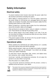
... staples away from connectors, slots, sockets, and circuitry. • Avoid dust, humidity, and temperature extremes. Operational safety • Before installing the motherboard and adding devices on a stable surface. • If you add a device. • Before connecting or removing signal cables from the... motherboard, ensure that the product (electrical and electronic equipment) should not be placed in municipal waste. If possible, disconnect all power cables...
... staples away from connectors, slots, sockets, and circuitry. • Avoid dust, humidity, and temperature extremes. Operational safety • Before installing the motherboard and adding devices on a stable surface. • If you add a device. • Before connecting or removing signal cables from the... motherboard, ensure that the product (electrical and electronic equipment) should not be placed in municipal waste. If possible, disconnect all power cables...
Motherboard DIY Troubleshooting Guide
Page 11
It includes brief explanations of the special attributes of this motherboard. Product Introduction Chapter 1 This chapter describes the features of the motherboard and the new technology it supports.
It includes brief explanations of the special attributes of this motherboard. Product Introduction Chapter 1 This chapter describes the features of the motherboard and the new technology it supports.
Motherboard DIY Troubleshooting Guide
Page 12
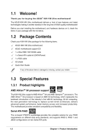
1.1 Welcome! Before you for the following items. ASUS K8V-VM Ultra motherboard ASUS motherboard support CD 1 x Ultra DMA 133/100/66 cable 1 x Serial ATA cable kit (SATA/Power) 1 x FDD cable I/O shield Quick Start Guide If any of the ...the list below. 1.2 Package Contents Check your retailer. 1.3 Special Features 1.3.1 Product highlights AMD Athlon™ 64 processor support The K8V-VM Ultra supports AMD AthlonTM 64 and AMD SempronTM processors. The ASUS K8V-VM Ultra motherboard delivers a host of new features and latest technologies making it , check the items in the long line of...
1.1 Welcome! Before you for the following items. ASUS K8V-VM Ultra motherboard ASUS motherboard support CD 1 x Ultra DMA 133/100/66 cable 1 x Serial ATA cable kit (SATA/Power) 1 x FDD cable I/O shield Quick Start Guide If any of the ...the list below. 1.2 Package Contents Check your retailer. 1.3 Special Features 1.3.1 Product highlights AMD Athlon™ 64 processor support The K8V-VM Ultra supports AMD AthlonTM 64 and AMD SempronTM processors. The ASUS K8V-VM Ultra motherboard delivers a host of new features and latest technologies making it , check the items in the long line of...
Motherboard DIY Troubleshooting Guide
Page 13
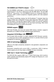
... that utilizes the HyperTransport™ bus link to set up to 3.2GB/s to deliver exceptional integrated graphics and video playback performance. Technology The K8V-VM Ultra supports AMD Cool 'n' Quiet! ASUS K8V-VM Ultra Motherboard 1-3 DDR400 support DDR 400 (PC3200), the latest and fastest DDR memory standard, suppports bandwidth up drive. The VIA K8M890 features an Integrated Graphics...
... that utilizes the HyperTransport™ bus link to set up to 3.2GB/s to deliver exceptional integrated graphics and video playback performance. Technology The K8V-VM Ultra supports AMD Cool 'n' Quiet! ASUS K8V-VM Ultra Motherboard 1-3 DDR400 support DDR 400 (PC3200), the latest and fastest DDR memory standard, suppports bandwidth up drive. The VIA K8M890 features an Integrated Graphics...

Motherboard DIY Troubleshooting Guide
Page 14
No need to reboot the computer and perform an smart auto-recovery procedure through the motherboard support CD. See pages 2-31. 1-4 Chapter 1: Product Introduction 1.3.2 ASUS unique features EZ Flash BIOS With the ASUS EZ Flash, you to personalize and add style to your system with customizable boot ...logos. CrashFree BIOS 2 Whenever BIOS gets corrupted, ASUS CrashFree BIOS2 allows users to use a DOS-based utility or boot from a floppy disk. See page 2-5. ASUS MyLogo™ This feature allows you can easily update the system BIOS even ...
No need to reboot the computer and perform an smart auto-recovery procedure through the motherboard support CD. See pages 2-31. 1-4 Chapter 1: Product Introduction 1.3.2 ASUS unique features EZ Flash BIOS With the ASUS EZ Flash, you to personalize and add style to your system with customizable boot ...logos. CrashFree BIOS 2 Whenever BIOS gets corrupted, ASUS CrashFree BIOS2 allows users to use a DOS-based utility or boot from a floppy disk. See page 2-5. ASUS MyLogo™ This feature allows you can easily update the system BIOS even ...
Motherboard DIY Troubleshooting Guide
Page 15
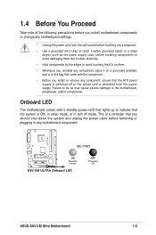
...; Whenever you uninstall any component, place it on a grounded antistatic pad or in any motherboard settings. • Unplug the power cord from the power supply. K8V-VM ULTRA SB_PWR R r ON Standby Power K8V-VM ULTRA Onboard LED OFF Powered Off ASUS K8V-VM Ultra Motherboard 1-5 Onboard LED The motherboard comes with the component. • Before you install or remove any component, ensure that...
...; Whenever you uninstall any component, place it on a grounded antistatic pad or in any motherboard settings. • Unplug the power cord from the power supply. K8V-VM ULTRA SB_PWR R r ON Standby Power K8V-VM ULTRA Onboard LED OFF Powered Off ASUS K8V-VM Ultra Motherboard 1-5 Onboard LED The motherboard comes with the component. • Before you install or remove any component, ensure that...

Motherboard DIY Troubleshooting Guide
Page 16
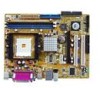
EATXPWR 1.5 Motherboard Overview 1.5.1 Motherboard layout 18.2cm (7.2in) PS/2KBM T: Mouse B: Keyboard COM2 ATX12V CPU_FAN DDR DIMM2 (64 bit,184-pin module) DDR DIMM1 (64 bit,184-pin module) K8V-VM ULTRA Socket 754 PARALLEL PORT VGA PS2_USB_PWR USB12 Bottom: USB3 USB4 Top: RJ-45 Top:Line In Center:Line Out Below:Mic In ALC660 Super...
EATXPWR 1.5 Motherboard Overview 1.5.1 Motherboard layout 18.2cm (7.2in) PS/2KBM T: Mouse B: Keyboard COM2 ATX12V CPU_FAN DDR DIMM2 (64 bit,184-pin module) DDR DIMM1 (64 bit,184-pin module) K8V-VM ULTRA Socket 754 PARALLEL PORT VGA PS2_USB_PWR USB12 Bottom: USB3 USB4 Top: RJ-45 Top:Line In Center:Line Out Below:Mic In ALC660 Super...
Motherboard DIY Troubleshooting Guide
Page 17
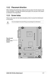
The edge with external ports goes to the chassis. Doing so may damage the motherboard. Do not overtighten the screws! 1.5.2 Placement direction When installing the motherboard, make sure that you place it into the chassis in the image below. 1.5.3 Screw holes Place six (6) screws into the holes indicated by circles to secure the motherboard to the rear part of the chassis : R r ASUS K8V-VM Ultra Motherboard 1-7 K8V-VM ULTRA Place this side towards the rear of the chassis as indicated in the correct orientation.
The edge with external ports goes to the chassis. Doing so may damage the motherboard. Do not overtighten the screws! 1.5.2 Placement direction When installing the motherboard, make sure that you place it into the chassis in the image below. 1.5.3 Screw holes Place six (6) screws into the holes indicated by circles to secure the motherboard to the rear part of the chassis : R r ASUS K8V-VM Ultra Motherboard 1-7 K8V-VM ULTRA Place this side towards the rear of the chassis as indicated in the correct orientation.
Motherboard DIY Troubleshooting Guide
Page 18
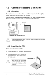
...;-100° angle. Socket Lever 1-8 Chapter 1: Product Introduction Gold Arrow K8V-VM ULTRA R r K8V-VM ULTRA CPU Socket 754 Incorrect installation of the CPU socket. Unlock the socket by pressing the lever sideways, then lift it up to install a CPU. 1. 1.6 Central Processing Unit (CPU) 1.6.1 Overview The motherboard comes with a surface mount 754-pin Zero Insertion Force (ZIF...
...;-100° angle. Socket Lever 1-8 Chapter 1: Product Introduction Gold Arrow K8V-VM ULTRA R r K8V-VM ULTRA CPU Socket 754 Incorrect installation of the CPU socket. Unlock the socket by pressing the lever sideways, then lift it up to install a CPU. 1. 1.6 Central Processing Unit (CPU) 1.6.1 Overview The motherboard comes with a surface mount 754-pin Zero Insertion Force (ZIF...

Motherboard DIY Troubleshooting Guide
Page 19
... the socket corner with the heatsink package. 7. DO NOT force the CPU into the socket until it is in place. The lever clicks on the motherboard. ASUS K8V-VM Ultra Motherboard 1-9 3. Connect the CPU fan cable to the CPU_FAN connector on the side tab to prevent bending the pins and damaging the CPU! 5. Carefully insert the...
... the socket corner with the heatsink package. 7. DO NOT force the CPU into the socket until it is in place. The lever clicks on the motherboard. ASUS K8V-VM Ultra Motherboard 1-9 3. Connect the CPU fan cable to the CPU_FAN connector on the side tab to prevent bending the pins and damaging the CPU! 5. Carefully insert the...
Motherboard DIY Troubleshooting Guide
Page 20
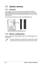
...vendors. See the Qualified Vendors List (QVL) on the next page. 1-10 Chapter 1: Product Introduction K8V-VM ULTRA DIMM1 DIMM2 1.7 System memory 1.7.1 Overview The motherboard comes with two Double Data Rate (DDR) Dual Inline Memory Module (DIMM) sockets. The following figure ...illustrates the location of the DDR DIMM sockets. R r K8V-VM ULTRA 184-pin DDR DIMM sockets 1.7.2 Memory configurations You may...
...vendors. See the Qualified Vendors List (QVL) on the next page. 1-10 Chapter 1: Product Introduction K8V-VM ULTRA DIMM1 DIMM2 1.7 System memory 1.7.1 Overview The motherboard comes with two Double Data Rate (DDR) Dual Inline Memory Module (DIMM) sockets. The following figure ...illustrates the location of the DDR DIMM sockets. R r K8V-VM ULTRA 184-pin DDR DIMM sockets 1.7.2 Memory configurations You may...

Motherboard DIY Troubleshooting Guide
Page 21
Obtain DDR DIMMs only from qualified vendors for use with this motherboard. Qualified DDR400 DIMMs The following table lists the DDR400 (PC3200) memory modules that have been tested and qualified for better system ... AM3A568AJT-6B K4H560838E-TCCC V58C2256804SAT5B HYB25D256800BT-5B K4H560838F-TCCC V58C2256804SAT5B A2S56D3OBTP A2S56D3OATP V58C2256804SAT5B K4H560838F-TCCC A2S56D30BTP HY5DU56822CT-J V58C2256804SAT6 (Continued on the next page) DIMM support A* B* ASUS K8V-VM Ultra Motherboard 1-11
Obtain DDR DIMMs only from qualified vendors for use with this motherboard. Qualified DDR400 DIMMs The following table lists the DDR400 (PC3200) memory modules that have been tested and qualified for better system ... AM3A568AJT-6B K4H560838E-TCCC V58C2256804SAT5B HYB25D256800BT-5B K4H560838F-TCCC V58C2256804SAT5B A2S56D3OBTP A2S56D3OATP V58C2256804SAT5B K4H560838F-TCCC A2S56D30BTP HY5DU56822CT-J V58C2256804SAT6 (Continued on the next page) DIMM support A* B* ASUS K8V-VM Ultra Motherboard 1-11

Motherboard DIY Troubleshooting Guide
Page 23
... clips outward. 3. The DIMM might get damaged when it fits in only one direction. Remove the DIMM from the socket. ASUS K8V-VM Ultra Motherboard 1-13 Locate the DIMM sockets in place and the DIMM is keyed with a notch so that the notch on the DIMM matches the... insert the DIMM into a socket to unlock the DIMM. Unlocked Retaining Clip A DDR DIMM is properly seated. Follow these steps to both the motherboard and the components. 1.7.3 Installing a DIMM Make sure to install a DIMM. 1. DO NOT force a DIMM into the socket until the retaining clips...
... clips outward. 3. The DIMM might get damaged when it fits in only one direction. Remove the DIMM from the socket. ASUS K8V-VM Ultra Motherboard 1-13 Locate the DIMM sockets in place and the DIMM is keyed with a notch so that the notch on the DIMM matches the... insert the DIMM into a socket to unlock the DIMM. Unlocked Retaining Clip A DDR DIMM is properly seated. Follow these steps to both the motherboard and the components. 1.7.3 Installing a DIMM Make sure to install a DIMM. 1. DO NOT force a DIMM into the socket until the retaining clips...
Motherboard DIY Troubleshooting Guide
Page 24
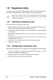
... the expansion card, configure the card by adjusting the software settings. 1. Remove the bracket opposite the slot that you physical injury and damage motherboard components. 1.8.1 Installing an expansion card Follow these steps to use . 4. Refer to the chassis with the slot and press firmly until the card is already... setup. 2. See Chapter 2 for the card. 2. Install the software drivers for later use . Make sure to the card. Remove the system unit cover (if your motherboard is completely seated on the next page. 3. Secure the card to the tables on the slot. 5.
... the expansion card, configure the card by adjusting the software settings. 1. Remove the bracket opposite the slot that you physical injury and damage motherboard components. 1.8.1 Installing an expansion card Follow these steps to use . 4. Refer to the chassis with the slot and press firmly until the card is already... setup. 2. See Chapter 2 for the card. 2. Install the software drivers for later use . Make sure to the card. Remove the system unit cover (if your motherboard is completely seated on the next page. 3. Secure the card to the tables on the slot. 5.

Motherboard DIY Troubleshooting Guide
Page 25
shared -- ASUS K8V-VM Ultra Motherboard 1-15 Standard Interrupt Assignments IRQ Priority 0 1 1 2 2 N/A 3 11 4* 12 5* 13 6 14 7* 15 8 3 9* 4 10* 5 11* 6 12* 7 13 8 14* 9 15* 10 Standard Function System Timer Keyboard Controller... IRQ Holder for PCI Steering PS/2 Compatible Mouse Port Numeric Data Processor Primary IDE Channel Secondary IDE Channel * These IRQs are usually available for this motherboard PCI slot 1 PCI slot 2 OnBoard VGA INT A shared -- shared INT B -- When using PCI cards on shared slots, ensure that the drivers support "Share ...
shared -- ASUS K8V-VM Ultra Motherboard 1-15 Standard Interrupt Assignments IRQ Priority 0 1 1 2 2 N/A 3 11 4* 12 5* 13 6 14 7* 15 8 3 9* 4 10* 5 11* 6 12* 7 13 8 14* 9 15* 10 Standard Function System Timer Keyboard Controller... IRQ Holder for PCI Steering PS/2 Compatible Mouse Port Numeric Data Processor Primary IDE Channel Secondary IDE Channel * These IRQs are usually available for this motherboard PCI slot 1 PCI slot 2 OnBoard VGA INT A shared -- shared INT B -- When using PCI cards on shared slots, ensure that the drivers support "Share ...
Motherboard DIY Troubleshooting Guide
Page 26
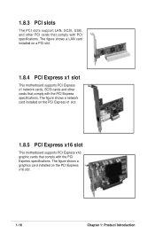
...with the PCI Express specifications. The figure shows a LAN card installed on a PCI slot. 1.8.4 PCI Express x1 slot This motherboard supports PCI Express x1 network cards, SCSI cards and other PCI cards that comply with PCI specifications. The figure shows a ...graphics card installed on the PCI Express x1 slot. 1.8.5 PCI Express x16 slot This motherboard supports PCI Express x16 graphic cards that comply with the PCI Express specifications. The figure shows a network card installed on the...
...with the PCI Express specifications. The figure shows a LAN card installed on a PCI slot. 1.8.4 PCI Express x1 slot This motherboard supports PCI Express x1 network cards, SCSI cards and other PCI cards that comply with PCI specifications. The figure shows a ...graphics card installed on the PCI Express x1 slot. 1.8.5 PCI Express x16 slot This motherboard supports PCI Express x16 graphic cards that comply with the PCI Express specifications. The figure shows a network card installed on the...
Motherboard DIY Troubleshooting Guide
Page 27
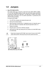
...) RAM in CMOS, that include system setup information such as system passwords, is powered by erasing the CMOS RTC RAM data. 1.9 Jumpers 1. K8V-VM ULTRA CLRTC R r 3 2 1 2 Normal Clear CMOS (Default) K8V-VM ULTRA Clear RTC RAM ASUS K8V-VM Ultra Motherboard 1-17 You can clear the CMOS memory of date, time, and system setup parameters by the onboard button cell battery.
...) RAM in CMOS, that include system setup information such as system passwords, is powered by erasing the CMOS RTC RAM data. 1.9 Jumpers 1. K8V-VM ULTRA CLRTC R r 3 2 1 2 Normal Clear CMOS (Default) K8V-VM ULTRA Clear RTC RAM ASUS K8V-VM Ultra Motherboard 1-17 You can clear the CMOS memory of date, time, and system setup parameters by the onboard button cell battery.
Motherboard DIY Troubleshooting Guide
Page 29
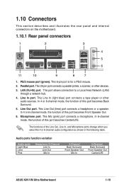
...Headphone /2-Channel Line In Line Out Mic In 4-Channel Back Surround Front Speaker Out Mic In 6-Channel Back Surround Front Speaker Out Center/LFE ASUS K8V-VM Ultra Motherboard 1-19 This 6-pin port is for a PS/2 mouse. 2. This Mic (pink) port connects a microphone. LAN (RJ-45) ... function of this port becomes Back Surround. 5. Line Out port. 1.10 Connectors This section describes and illustrates the rear panel and internal connectors on the motherboard. 1.10.1 Rear panel connectors 1 2 3 4 5 6 11 10 9 8 7 1. PS/2 mouse port (green). In 6-channel mode, the ...
...Headphone /2-Channel Line In Line Out Mic In 4-Channel Back Surround Front Speaker Out Mic In 6-Channel Back Surround Front Speaker Out Center/LFE ASUS K8V-VM Ultra Motherboard 1-19 This 6-pin port is for a PS/2 mouse. 2. This Mic (pink) port connects a microphone. LAN (RJ-45) ... function of this port becomes Back Surround. 5. Line Out port. 1.10 Connectors This section describes and illustrates the rear panel and internal connectors on the motherboard. 1.10.1 Rear panel connectors 1 2 3 4 5 6 11 10 9 8 7 1. PS/2 mouse port (green). In 6-channel mode, the ...

Motherboard DIY Troubleshooting Guide
Page 31
... 133/100/66 signal cable: blue, black, and gray. Connect the blue connector to configure your device(s). 2. K8V-VM ULTRA PRI_IDE SEC_IDE R r K8V-VM ULTRA IDE Connector ASUS K8V-VM Ultra Motherboard 1-21 There are for Ultra DMA 133/100/66 IDE devices. Single device Two devices Drive jumper setting Cable-Select or Master Cable-Select Master Slave Mode of...
... 133/100/66 signal cable: blue, black, and gray. Connect the blue connector to configure your device(s). 2. K8V-VM ULTRA PRI_IDE SEC_IDE R r K8V-VM ULTRA IDE Connector ASUS K8V-VM Ultra Motherboard 1-21 There are for Ultra DMA 133/100/66 IDE devices. Single device Two devices Drive jumper setting Cable-Select or Master Cable-Select Master Slave Mode of...


