F2A55-M LK2 User's Manual
Page 11
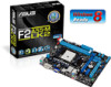
... SPDIF_OUTCOM1USBPW5-8 USB78 AAFP AMD® A55 SATA3G_1 SATA3G_2 SPEAKER CLRTC USB56 32Mb BIOS SATA3G_3 SATA3G_4 F_PANEL ASUS F2A55-M LK2 Series motherboard User Guide 2 x Serial ATA 3.0 Gb/s cables 1 x I/O Shield User Guide Support DVD • F2A55-M LK2 Series motherboards include F2A55-M LK2 PLUS and F2A55-M LK2 models. Actual product specifications may vary with different models. xi The package contents vary from...
... SPDIF_OUTCOM1USBPW5-8 USB78 AAFP AMD® A55 SATA3G_1 SATA3G_2 SPEAKER CLRTC USB56 32Mb BIOS SATA3G_3 SATA3G_4 F_PANEL ASUS F2A55-M LK2 Series motherboard User Guide 2 x Serial ATA 3.0 Gb/s cables 1 x I/O Shield User Guide Support DVD • F2A55-M LK2 Series motherboards include F2A55-M LK2 PLUS and F2A55-M LK2 models. Actual product specifications may vary with different models. xi The package contents vary from...
F2A55-M LK2 User's Manual
Page 13
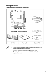
... more confusion of Line-in one small, energy-efficient design to enable accelerated performance and an industry-leading visual experience. ASUS F2A55-M LK2 Series 1-1 This revolutionary APU (Accelerated Processing Unit) combines processing power and advanced DirectX 11 graphics in , Line-out... ACPI management function to provide efficient power management for advanced operating systems. 100% All High-quality Conductive Polymer Capacitors (F2A55-M LK2 PLUS only) This motherboard uses all high-quality conductive polymer capacitors for durability, improved lifespan, and enhanced thermal capacity....
... more confusion of Line-in one small, energy-efficient design to enable accelerated performance and an industry-leading visual experience. ASUS F2A55-M LK2 Series 1-1 This revolutionary APU (Accelerated Processing Unit) combines processing power and advanced DirectX 11 graphics in , Line-out... ACPI management function to provide efficient power management for advanced operating systems. 100% All High-quality Conductive Polymer Capacitors (F2A55-M LK2 PLUS only) This motherboard uses all high-quality conductive polymer capacitors for durability, improved lifespan, and enhanced thermal capacity....
F2A55-M LK2 User's Manual
Page 15
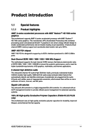
... the CPU parameters to personalize your favorite photos into 256-color boot logos to their default settings. ASUS MyLogo2™ Turn your system. ASUS CrashFree BIOS 3 ASUS CrashFree BIOS 3 allows you to energy consumptions. C.P.R. (CPU Parameter Recall) The BIOS C.P.R. ErP ...related voltages, remotely control the system via a mobile device, and other easy-to a quiet and cool computing environment. ASUS F2A55-M LK2 Series 1-3 C.P.R. It allows you to reduce carbon footprint of creating environment-friendly and energyefficient products through product design and ...
... the CPU parameters to personalize your favorite photos into 256-color boot logos to their default settings. ASUS MyLogo2™ Turn your system. ASUS CrashFree BIOS 3 ASUS CrashFree BIOS 3 allows you to energy consumptions. C.P.R. (CPU Parameter Recall) The BIOS C.P.R. ErP ...related voltages, remotely control the system via a mobile device, and other easy-to a quiet and cool computing environment. ASUS F2A55-M LK2 Series 1-3 C.P.R. It allows you to reduce carbon footprint of creating environment-friendly and energyefficient products through product design and ...
F2A55-M LK2 User's Manual
Page 17
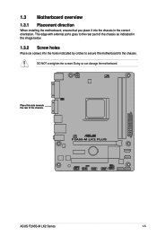
1.3 Motherboard overview 1.3.1 Placement direction When installing the motherboard, ensure that you place it into the holes indicated by circles to secure the motherboard to the rear part of the chassis. Doing so can damage the motherboard. Place this side towards the rear of the chassis as indicated in the image below. 1.3.2 Screw holes Place six screws into the chassis in the correct orientation. F2A55-M LK2 PLUS ASUS F2A55-M LK2 Series 1-5 DO NOT overtighten the screws! The edge with external ports goes to the chassis.
1.3 Motherboard overview 1.3.1 Placement direction When installing the motherboard, ensure that you place it into the holes indicated by circles to secure the motherboard to the rear part of the chassis. Doing so can damage the motherboard. Place this side towards the rear of the chassis as indicated in the image below. 1.3.2 Screw holes Place six screws into the chassis in the correct orientation. F2A55-M LK2 PLUS ASUS F2A55-M LK2 Series 1-5 DO NOT overtighten the screws! The edge with external ports goes to the chassis.
F2A55-M LK2 User's Manual
Page 19
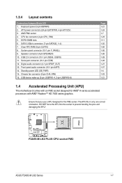
... AAFP) 14. Ensure that you use a APU designed for AMD® A-series accelerated processors with AMD® Radeon™ HD 7000 series graphics. F2A55-M LK2 PLUS F2A55-M LK2 PLUS CPU socket FM2 ASUS F2A55-M LK2 Series 1-7 Serial port connector (10-1 pin COM) 12. USB 2.0 connectors (10-1 pin USB56, USB78) 11. The APU fits in only one correct...
... AAFP) 14. Ensure that you use a APU designed for AMD® A-series accelerated processors with AMD® Radeon™ HD 7000 series graphics. F2A55-M LK2 PLUS F2A55-M LK2 PLUS CPU socket FM2 ASUS F2A55-M LK2 Series 1-7 Serial port connector (10-1 pin COM) 12. USB 2.0 connectors (10-1 pin USB56, USB78) 11. The APU fits in only one correct...

F2A55-M LK2 User's Manual
Page 21
1.4.2 APU heatsink and fan assembly installation Apply the Thermal Interface Material to the APU heatsink and APU before you install the heatsink and fan if necessary. To install the APU heatsink and fan assembly 1 2 3 4 5 ASUS F2A55-M LK2 Series 1-9
1.4.2 APU heatsink and fan assembly installation Apply the Thermal Interface Material to the APU heatsink and APU before you install the heatsink and fan if necessary. To install the APU heatsink and fan assembly 1 2 3 4 5 ASUS F2A55-M LK2 Series 1-9
F2A55-M LK2 User's Manual
Page 23
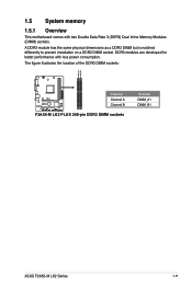
1.5 System memory 1.5.1 Overview This motherboard comes with less power consumption. DDR3 modules are developed for better performance with two Double Data Rate 3 (DDR3) Dual Inline Memory Modules (DIMM) sockets. The figure illustrates the location of the DDR3 DIMM sockets: DIMM_A1 DIMM_B1 F2A55-M LK2 PLUS Channel Channel A Channel B F2A55-M LK2 PLUS 240-pin DDR3 DIMM sockets Sockets DIMM_A1 DIMM_B1 ASUS F2A55-M LK2 Series 1-11 A DDR3 module has the same physical dimensions as a DDR2 DIMM but is notched differently to prevent installation on a DDR2 DIMM socket.
1.5 System memory 1.5.1 Overview This motherboard comes with less power consumption. DDR3 modules are developed for better performance with two Double Data Rate 3 (DDR3) Dual Inline Memory Modules (DIMM) sockets. The figure illustrates the location of the DDR3 DIMM sockets: DIMM_A1 DIMM_B1 F2A55-M LK2 PLUS Channel Channel A Channel B F2A55-M LK2 PLUS 240-pin DDR3 DIMM sockets Sockets DIMM_A1 DIMM_B1 ASUS F2A55-M LK2 Series 1-11 A DDR3 module has the same physical dimensions as a DDR2 DIMM but is notched differently to prevent installation on a DDR2 DIMM socket.

F2A55-M LK2 User's Manual
Page 27
ASUS F2A55-M LK2 Series 1-15 Visit the ASUS website at www.asus.com for the latest QVL. Timing Voltage Crucial CT12864BA1067.8FF 1GB SS ELPIDA EBJ21UE8EDF0-AE-F 2GB DS KINGSTON KVR1066D3N7/1G(low profile) 1GB SS KINGSTON ...
ASUS F2A55-M LK2 Series 1-15 Visit the ASUS website at www.asus.com for the latest QVL. Timing Voltage Crucial CT12864BA1067.8FF 1GB SS ELPIDA EBJ21UE8EDF0-AE-F 2GB DS KINGSTON KVR1066D3N7/1G(low profile) 1GB SS KINGSTON ...
F2A55-M LK2 User's Manual
Page 29
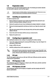
... components. 1.6.1 Installing an expansion card To install an expansion card: 1. See Chapter 2 for the card. 2. Unplug the power cord before adding or removing expansion cards. ASUS F2A55-M LK2 Series 1-17 Align the card connector with it by adjusting the software settings. 1. Remove the bracket opposite the slot that you removed earlier. 6. Before installing...
... components. 1.6.1 Installing an expansion card To install an expansion card: 1. See Chapter 2 for the card. 2. Unplug the power cord before adding or removing expansion cards. ASUS F2A55-M LK2 Series 1-17 Align the card connector with it by adjusting the software settings. 1. Remove the bracket opposite the slot that you removed earlier. 6. Before installing...
F2A55-M LK2 User's Manual
Page 31
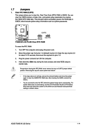
...then move the jumper again to clear the Real Time Clock (RTC) RAM in CMOS, which include system setup information such as system passwords. ASUS F2A55-M LK2 Series 1-19 Turn OFF the computer and unplug the power cord. 2. Keep the cap on CLRTC jumper default position. Removing the cap will ...due to pins 2-3. Shut down the key during the boot process and enter BIOS setup to default values. 1.7 Jumpers 1. F2A55-M LK2 PLUS CLRTC 12 23 Normal (Default) Clear RTC F2A55-M LK2 PLUS Clear RTC RAM To erase the RTC RAM: 1. Plug the power cord and turn ON the computer. 4. Move ...
...then move the jumper again to clear the Real Time Clock (RTC) RAM in CMOS, which include system setup information such as system passwords. ASUS F2A55-M LK2 Series 1-19 Turn OFF the computer and unplug the power cord. 2. Keep the cap on CLRTC jumper default position. Removing the cap will ...due to pins 2-3. Shut down the key during the boot process and enter BIOS setup to default values. 1.7 Jumpers 1. F2A55-M LK2 PLUS CLRTC 12 23 Normal (Default) Clear RTC F2A55-M LK2 PLUS Clear RTC RAM To erase the RTC RAM: 1. Plug the power cord and turn ON the computer. 4. Move ...

F2A55-M LK2 User's Manual
Page 33
..., CD, DVD player, or other audio sources. 4. Refer to a microphone. Microphone port (pink). This port connects to the audio configuration table below for a PS/2 mouse. 2. ASUS F2A55-M LK2 Series 1-21
..., CD, DVD player, or other audio sources. 4. Refer to a microphone. Microphone port (pink). This port connects to the audio configuration table below for a PS/2 mouse. 2. ASUS F2A55-M LK2 Series 1-21
F2A55-M LK2 User's Manual
Page 35
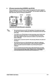
...the power is inadequate. • If you use a PSU with higher power output when configuring a system with a minimum of 300W. ASUS F2A55-M LK2 Series 1-23 The plugs from the power supply are uncertain about the minimum power supply requirement for an ATX power supply. The system ... NOT forget to fit these connectors in only one orientation. com/PowerSupplyCalculator/PSCalculator.aspx?SLanguage=en-us for details. ATX12V EATXPWR +12V DC +12V DC F2A55-M LK2 PLUS GND GND +3 Volts +12 Volts +12 Volts +5V Standby Power OK GND PIN 1 +5 Volts GND +5 Volts GND +3 Volts +3 Volts PIN 1...
...the power is inadequate. • If you use a PSU with higher power output when configuring a system with a minimum of 300W. ASUS F2A55-M LK2 Series 1-23 The plugs from the power supply are uncertain about the minimum power supply requirement for an ATX power supply. The system ... NOT forget to fit these connectors in only one orientation. com/PowerSupplyCalculator/PSCalculator.aspx?SLanguage=en-us for details. ATX12V EATXPWR +12V DC +12V DC F2A55-M LK2 PLUS GND GND +3 Volts +12 Volts +12 Volts +5V Standby Power OK GND PIN 1 +5 Volts GND +5 Volts GND +3 Volts +3 Volts PIN 1...
F2A55-M LK2 User's Manual
Page 37
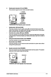
F_PANEL PWR LED PWR BTN PIN 1 F2A55-M LK2 PLUS HD_LED RESET F2A55-M LK2 PLUS System panel connector • System power LED (2-pin PLED) This 2-pin connector is for the chassis-mounted reset button for system reboot without turning ... connector is for the HDD Activity LED. Ground Reset 4. Speaker connector (4-pin SPEAKER) The 4-pin connector is for the chassis-mounted system warning speaker. SPEAKER F2A55-M LK2 PLUS PIN 1 F2A55-M LK2 PLUS Speaker Out Connector +5V GND GND Speaker Out ASUS F2A55-M LK2 Series 1-25
F_PANEL PWR LED PWR BTN PIN 1 F2A55-M LK2 PLUS HD_LED RESET F2A55-M LK2 PLUS System panel connector • System power LED (2-pin PLED) This 2-pin connector is for the chassis-mounted reset button for system reboot without turning ... connector is for the HDD Activity LED. Ground Reset 4. Speaker connector (4-pin SPEAKER) The 4-pin connector is for the chassis-mounted system warning speaker. SPEAKER F2A55-M LK2 PLUS PIN 1 F2A55-M LK2 PLUS Speaker Out Connector +5V GND GND Speaker Out ASUS F2A55-M LK2 Series 1-25
F2A55-M LK2 User's Manual
Page 39
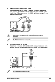
...10-1 pin USB56, USB78) These connectors are for a serial (COM) port. ASUS F2A55-M LK2 Series 1-27 USB78 USB56 USB+5V USB_P6USB_P6+ GND NC USB+5V USB_P8USB_P8+ GND NC F2A55-M LK2 PLUS PIN 1 PIN 1 USB+5V USB_P5USB_P5+ GND USB+5V USB_P7USB_P7+ GND F2A55-M LK2 PLUS USB2.0 connectors Never connect a 1394 cable to 480Mbps connection speed. The USB... module to a slot opening at the back of the system chassis. COM1 CTS DSR DTR RXD RI PIN 1 RTS GND TXD DCD F2A55-M LK2 PLUS F2A55-M LK2 PLUS Serial port (COM1) connector The COM module is purchased separately. 9.
...10-1 pin USB56, USB78) These connectors are for a serial (COM) port. ASUS F2A55-M LK2 Series 1-27 USB78 USB56 USB+5V USB_P6USB_P6+ GND NC USB+5V USB_P8USB_P8+ GND NC F2A55-M LK2 PLUS PIN 1 PIN 1 USB+5V USB_P5USB_P5+ GND USB+5V USB_P7USB_P7+ GND F2A55-M LK2 PLUS USB2.0 connectors Never connect a 1394 cable to 480Mbps connection speed. The USB... module to a slot opening at the back of the system chassis. COM1 CTS DSR DTR RXD RI PIN 1 RTS GND TXD DCD F2A55-M LK2 PLUS F2A55-M LK2 PLUS Serial port (COM1) connector The COM module is purchased separately. 9.
F2A55-M LK2 User's Manual
Page 42
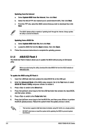
...on a single partition. • DO NOT shut down or reset the system while updating the BIOS to prevent system boot failure! 2-2 ASUS F2A55-M LK2 Series From the FTP site, select the BIOS version that contains the latest BIOS file to find the USB flash disk that contains the ... formatted using this utility, download the latest BIOS file from a BIOS file a. Follow the onscreen instructions to complete the updating process. 2.1.2 ASUS EZ Flash 2 The ASUS EZ Flash 2 feature allows you wish to update the BIOS without using EZ Flash 2: 1. Press to switch to avail all its features....
...on a single partition. • DO NOT shut down or reset the system while updating the BIOS to prevent system boot failure! 2-2 ASUS F2A55-M LK2 Series From the FTP site, select the BIOS version that contains the latest BIOS file to find the USB flash disk that contains the ... formatted using this utility, download the latest BIOS file from a BIOS file a. Follow the onscreen instructions to complete the updating process. 2.1.2 ASUS EZ Flash 2 The ASUS EZ Flash 2 feature allows you wish to update the BIOS without using EZ Flash 2: 1. Press to switch to avail all its features....
F2A55-M LK2 User's Manual
Page 44
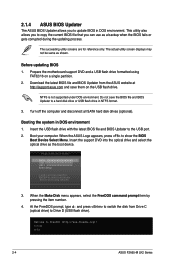
...save the BIOS file and BIOS Updater to Drive D (USB flash drive). The succeeding utility screens are for reference only. C:\>d: D:\> 2-4 ASUS F2A55-M LK2 Series Before updating BIOS 1. Do not save them on a single partition. 2. When the Make Disk menu appears, select the FreeDOS command prompt... the support DVD into the optical drive and select the optical drive as shown. NTFS is not supported under DOS environment. When the ASUS Logo appears, press to boot using FAT32/16 on the USB flash drive. Please select boot device: SATA: XXXXXXXXXXXXXXXX USB XXXXXXXXXXXXXXXXX UEFI:...
...save the BIOS file and BIOS Updater to Drive D (USB flash drive). The succeeding utility screens are for reference only. C:\>d: D:\> 2-4 ASUS F2A55-M LK2 Series Before updating BIOS 1. Do not save them on a single partition. 2. When the Make Disk menu appears, select the FreeDOS command prompt... the support DVD into the optical drive and select the optical drive as shown. NTFS is not supported under DOS environment. When the ASUS Logo appears, press to boot using FAT32/16 on the USB flash drive. Please select boot device: SATA: XXXXXXXXXXXXXXXX USB XXXXXXXXXXXXXXXXX UEFI:...

F2A55-M LK2 User's Manual
Page 46
... can change modes from the Exit menu or from the operating system. • The BIOS setup screens shown in the EZ Mode/Advanced Mode screen. 2-6 ASUS F2A55-M LK2 Series If the system becomes unstable after changing any BIOS settings, load the default settings to ensure system compatibility and stability. Do this option only...
... can change modes from the Exit menu or from the operating system. • The BIOS setup screens shown in the EZ Mode/Advanced Mode screen. 2-6 ASUS F2A55-M LK2 Series If the system becomes unstable after changing any BIOS settings, load the default settings to ensure system compatibility and stability. Do this option only...

F2A55-M LK2 User's Manual
Page 48
... example of the screen has the following sections for special functions For selecting the exit options and loading default settings 2-8 ASUS F2A55-M LK2 Series To access the EZ Mode, click Exit, then select ASUS EZ Mode. Advanced Mode The Advanced Mode provides advanced options for experienced end-users to the following main items: Main...
... example of the screen has the following sections for special functions For selecting the exit options and loading default settings 2-8 ASUS F2A55-M LK2 Series To access the EZ Mode, click Exit, then select ASUS EZ Mode. Advanced Mode The Advanced Mode provides advanced options for experienced end-users to the following main items: Main...

F2A55-M LK2 User's Manual
Page 50
... you set the system date, time, language, and security settings. 2.3.1 System Language [English] Allows you enter the Advanced Mode of the screen show Installed. 2-10 ASUS F2A55-M LK2 Series After you have forgotten your BIOS password, erase the CMOS Real Time Clock (RTC) RAM to erase the RTC RAM. • The Administrator or...
... you set the system date, time, language, and security settings. 2.3.1 System Language [English] Allows you enter the Advanced Mode of the screen show Installed. 2-10 ASUS F2A55-M LK2 Series After you have forgotten your BIOS password, erase the CMOS Real Time Clock (RTC) RAM to erase the RTC RAM. • The Administrator or...

F2A55-M LK2 User's Manual
Page 52
The configuration options for this section vary depending on the CPU and DIMM model you to configure overclocking-related items. Be cautious when changing the settings of the Ai Tweaker menu items. Incorrect field values can cause the system to display the following items: 2-12 ASUS F2A55-M LK2 Series Scroll down to malfunction. 2.4 Ai Tweaker menu The Ai Tweaker menu items allow you installed on the motherboard.
The configuration options for this section vary depending on the CPU and DIMM model you to configure overclocking-related items. Be cautious when changing the settings of the Ai Tweaker menu items. Incorrect field values can cause the system to display the following items: 2-12 ASUS F2A55-M LK2 Series Scroll down to malfunction. 2.4 Ai Tweaker menu The Ai Tweaker menu items allow you installed on the motherboard.


