
F2A55-M LK2 User's Manual
Page 1
Motherboard F2A55-M LK2 Series • F2A55-M LK2 • F2A55-M LK2 PLUS
Motherboard F2A55-M LK2 Series • F2A55-M LK2 • F2A55-M LK2 PLUS
F2A55-M LK2 User's Manual
Page 3
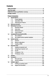
Contents Safety information...vi About this guide...vii F2A55-M LK2 Series specifications summary ix Package contents...xi Product introduction 1.1 Special features 1-1 1.1.1 Product highlights 1-1 1.1.2 ASUS DIGI+ VRM 1-2 1.1.3 ASUS Exclusive Features 1-2 1.2 Before you proceed 1-4 1.3 Motherboard overview 1-5 1.3.1 Placement direction 1-5 1.3.2 Screw holes 1-5 1.3.3 Motherboard layout 1-6 1.3.4 Layout contents 1-7 1.4 Accelerated Processing Unit (APU 1-7 1.4.1 APU installation 1-8 1.4.2 APU heatsink and fan assembly installation 1-9 1.5 System memory 1-11...
Contents Safety information...vi About this guide...vii F2A55-M LK2 Series specifications summary ix Package contents...xi Product introduction 1.1 Special features 1-1 1.1.1 Product highlights 1-1 1.1.2 ASUS DIGI+ VRM 1-2 1.1.3 ASUS Exclusive Features 1-2 1.2 Before you proceed 1-4 1.3 Motherboard overview 1-5 1.3.1 Placement direction 1-5 1.3.2 Screw holes 1-5 1.3.3 Motherboard layout 1-6 1.3.4 Layout contents 1-7 1.4 Accelerated Processing Unit (APU 1-7 1.4.1 APU installation 1-8 1.4.2 APU heatsink and fan assembly installation 1-9 1.5 System memory 1-11...
F2A55-M LK2 User's Manual
Page 6
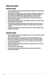
... not sure about the voltage of the electrical outlet you add a device. • Before connecting or removing signal cables from the motherboard, ensure that your power supply is broken, do not try to the correct voltage in your retailer. If you encounter technical problems with...or from the system, ensure that came with the product, contact a qualified service technician or your retailer. Operation safety • Before installing the motherboard and adding devices on a stable surface. • If you detect any damage, contact your dealer immediately. • To avoid short circuits, ...
... not sure about the voltage of the electrical outlet you add a device. • Before connecting or removing signal cables from the motherboard, ensure that your power supply is broken, do not try to the correct voltage in your retailer. If you encounter technical problems with...or from the system, ensure that came with the product, contact a qualified service technician or your retailer. Operation safety • Before installing the motherboard and adding devices on a stable surface. • If you detect any damage, contact your dealer immediately. • To avoid short circuits, ...
F2A55-M LK2 User's Manual
Page 7
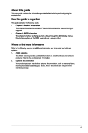
... the standard package. Where to find more information Refer to the ASUS contact information. 2. These documents are also provided. ASUS websites The ASUS website provides updated information on ASUS hardware and software products. Detailed descriptions of the BIOS parameters are not part of the motherboard and the new technology it supports. • Chapter 2: BIOS information... for additional information and for product and software updates. 1. How this guide This user guide contains the information you need when installing and configuring the motherboard. vii
... the standard package. Where to find more information Refer to the ASUS contact information. 2. These documents are also provided. ASUS websites The ASUS website provides updated information on ASUS hardware and software products. Detailed descriptions of the BIOS parameters are not part of the motherboard and the new technology it supports. • Chapter 2: BIOS information... for additional information and for product and software updates. 1. How this guide This user guide contains the information you need when installing and configuring the motherboard. vii
F2A55-M LK2 User's Manual
Page 11
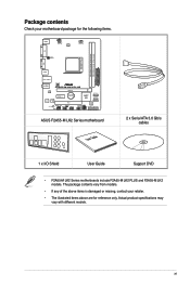
... SB_PWR SPDIF_OUTCOM1USBPW5-8 USB78 AAFP AMD® A55 SATA3G_1 SATA3G_2 SPEAKER CLRTC USB56 32Mb BIOS SATA3G_3 SATA3G_4 F_PANEL ASUS F2A55-M LK2 Series motherboard User Guide 2 x Serial ATA 3.0 Gb/s cables 1 x I/O Shield User Guide Support DVD • F2A55-M LK2 Series motherboards include F2A55-M LK2 PLUS and F2A55-M LK2 models. Package contents Check your retailer. • The illustrated items above items is damaged or missing...
... SB_PWR SPDIF_OUTCOM1USBPW5-8 USB78 AAFP AMD® A55 SATA3G_1 SATA3G_2 SPEAKER CLRTC USB56 32Mb BIOS SATA3G_3 SATA3G_4 F_PANEL ASUS F2A55-M LK2 Series motherboard User Guide 2 x Serial ATA 3.0 Gb/s cables 1 x I/O Shield User Guide Support DVD • F2A55-M LK2 Series motherboards include F2A55-M LK2 PLUS and F2A55-M LK2 models. Package contents Check your retailer. • The illustrated items above items is damaged or missing...
F2A55-M LK2 User's Manual
Page 13
... management function to provide efficient power management for advanced operating systems. 100% All High-quality Conductive Polymer Capacitors (F2A55-M LK2 PLUS only) This motherboard uses all high-quality conductive polymer capacitors for durability, improved lifespan, and enhanced thermal capacity. Dual-Channel DDR3 ...1600 / 1333 / 1066 MHz to boost the system's performance, and to enable accelerated performance and an industry-leading visual experience. ASUS F2A55-M LK2 Series 1-1 AMD® A55 FCH chipset AMD® A55 FCH is designed to support up to 5GT/s interface speed and ...
... management function to provide efficient power management for advanced operating systems. 100% All High-quality Conductive Polymer Capacitors (F2A55-M LK2 PLUS only) This motherboard uses all high-quality conductive polymer capacitors for durability, improved lifespan, and enhanced thermal capacity. Dual-Channel DDR3 ...1600 / 1333 / 1066 MHz to boost the system's performance, and to enable accelerated performance and an industry-leading visual experience. ASUS F2A55-M LK2 Series 1-1 AMD® A55 FCH chipset AMD® A55 FCH is designed to support up to 5GT/s interface speed and ...
F2A55-M LK2 User's Manual
Page 14
...F12 BIOS snapshot hotkey • F3 Shortcut for most precise power delivery. ASUS Anti-Surge Protection This special design protects expensive devices and the motherboard from damage caused by world-renowned ASUS quality, it easier for you to manage your bandwidth and allows you to...supply unit (PSU). 1-2 Chapter 1: Product introduction It offers you with difficult POST situations. 1.1.2 ASUS DIGI+ VRM DIGI+POWER CONTROL: Digital Power Design for the APU* ASUS motherboards using user-defined profiles. The effect is adjusted via either carefully developed automated modes, or by ...
...F12 BIOS snapshot hotkey • F3 Shortcut for most precise power delivery. ASUS Anti-Surge Protection This special design protects expensive devices and the motherboard from damage caused by world-renowned ASUS quality, it easier for you to manage your bandwidth and allows you to...supply unit (PSU). 1-2 Chapter 1: Product introduction It offers you with difficult POST situations. 1.1.2 ASUS DIGI+ VRM DIGI+POWER CONTROL: Digital Power Design for the APU* ASUS motherboards using user-defined profiles. The effect is adjusted via either carefully developed automated modes, or by ...
F2A55-M LK2 User's Manual
Page 15
...ASUS F2A55-M LK2 Series 1-3 AI Suite II With its user interface, ASUS AI Suite II integrates several ASUS... utilities and allows you to configure the overclocking settings, adjust the frequencies and related voltages, remotely control the system via a mobile device, and other easy-to-use helpful utilities. ASUS CrashFree BIOS 3 ASUS... CrashFree BIOS 3 allows you to restore a corrupted BIOS file from a USB storage device that contains the BIOS file. ASUS EZ Flash 2 ASUS...settings. C.P.R. ASUS Fan Xpert ASUS Fan Xpert ...
...ASUS F2A55-M LK2 Series 1-3 AI Suite II With its user interface, ASUS AI Suite II integrates several ASUS... utilities and allows you to configure the overclocking settings, adjust the frequencies and related voltages, remotely control the system via a mobile device, and other easy-to-use helpful utilities. ASUS CrashFree BIOS 3 ASUS... CrashFree BIOS 3 allows you to restore a corrupted BIOS file from a USB storage device that contains the BIOS file. ASUS EZ Flash 2 ASUS...settings. C.P.R. ASUS Fan Xpert ASUS Fan Xpert ...
F2A55-M LK2 User's Manual
Page 16
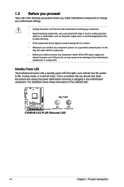
... indicate that you install or remove any component, switch off mode. SB_PWR F2A55-M LK2 PLUS ON OFF Standby Power Powered Off F2A55-M LK2 PLUS Onboard LED 1-4 Chapter 1: Product introduction 1.2 Before you proceed Take note of the onboard LED. Standby Power LED The motherboard comes with the component. • Before you should shut down the system...
... indicate that you install or remove any component, switch off mode. SB_PWR F2A55-M LK2 PLUS ON OFF Standby Power Powered Off F2A55-M LK2 PLUS Onboard LED 1-4 Chapter 1: Product introduction 1.2 Before you proceed Take note of the onboard LED. Standby Power LED The motherboard comes with the component. • Before you should shut down the system...
F2A55-M LK2 User's Manual
Page 17
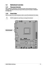
DO NOT overtighten the screws! Place this side towards the rear of the chassis as indicated in the image below. 1.3.2 Screw holes Place six screws into the chassis in the correct orientation. Doing so can damage the motherboard. F2A55-M LK2 PLUS ASUS F2A55-M LK2 Series 1-5 1.3 Motherboard overview 1.3.1 Placement direction When installing the motherboard, ensure that you place it into the holes indicated by circles to secure the motherboard to the rear part of the chassis. The edge with external ports goes to the chassis.
DO NOT overtighten the screws! Place this side towards the rear of the chassis as indicated in the image below. 1.3.2 Screw holes Place six screws into the chassis in the correct orientation. Doing so can damage the motherboard. F2A55-M LK2 PLUS ASUS F2A55-M LK2 Series 1-5 1.3 Motherboard overview 1.3.1 Placement direction When installing the motherboard, ensure that you place it into the holes indicated by circles to secure the motherboard to the rear part of the chassis. The edge with external ports goes to the chassis.
F2A55-M LK2 User's Manual
Page 18
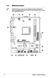
The package contents vary from models. 1.3.3 Motherboard layout F2A55-M LK2 Series motherboards include F2A55-M LK2 PLUS and F2A55-M LK2 models. The layout illustrations in this user guide are for F2A55-M LK2 PLUS only. 1 KBMS 2 3 4 5 17.3cm(6.8in) ATX12V DIGI +VRM CPU_FAN DDR3 DIMM_A1 (64bit, 240-pin module) DDR3 DIMM_B1 (64bit, 240-pin module) VGA DVI 16 ...
The package contents vary from models. 1.3.3 Motherboard layout F2A55-M LK2 Series motherboards include F2A55-M LK2 PLUS and F2A55-M LK2 models. The layout illustrations in this user guide are for F2A55-M LK2 PLUS only. 1 KBMS 2 3 4 5 17.3cm(6.8in) ATX12V DIGI +VRM CPU_FAN DDR3 DIMM_A1 (64bit, 240-pin module) DDR3 DIMM_B1 (64bit, 240-pin module) VGA DVI 16 ...
F2A55-M LK2 User's Manual
Page 19
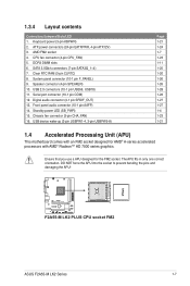
... 1-7 1-23 1-11 1-25 1-20 1-26 1-26 1-28 1-28 1-27 1-27 1-4 1-23 1-21 1.4 Accelerated Processing Unit (APU) This motherboard comes with AMD® Radeon™ HD 7000 series graphics. F2A55-M LK2 PLUS F2A55-M LK2 PLUS CPU socket FM2 ASUS F2A55-M LK2 Series 1-7 Keyboard power (3-pin KBPWR) 2. DDR3 DIMM slots 6. 1.3.4 Layout contents Connectors/Jumpers/Slots/LED 1. SATA 3.0Gb/s connectors (7-pin...
... 1-7 1-23 1-11 1-25 1-20 1-26 1-26 1-28 1-28 1-27 1-27 1-4 1-23 1-21 1.4 Accelerated Processing Unit (APU) This motherboard comes with AMD® Radeon™ HD 7000 series graphics. F2A55-M LK2 PLUS F2A55-M LK2 PLUS CPU socket FM2 ASUS F2A55-M LK2 Series 1-7 Keyboard power (3-pin KBPWR) 2. DDR3 DIMM slots 6. 1.3.4 Layout contents Connectors/Jumpers/Slots/LED 1. SATA 3.0Gb/s connectors (7-pin...
F2A55-M LK2 User's Manual
Page 23
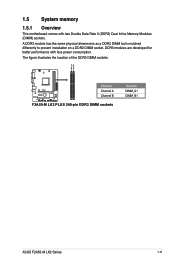
DDR3 modules are developed for better performance with two Double Data Rate 3 (DDR3) Dual Inline Memory Modules (DIMM) sockets. 1.5 System memory 1.5.1 Overview This motherboard comes with less power consumption. The figure illustrates the location of the DDR3 DIMM sockets: DIMM_A1 DIMM_B1 F2A55-M LK2 PLUS Channel Channel A Channel B F2A55-M LK2 PLUS 240-pin DDR3 DIMM sockets Sockets DIMM_A1 DIMM_B1 ASUS F2A55-M LK2 Series 1-11 A DDR3 module has the same physical dimensions as a DDR2 DIMM but is notched differently to prevent installation on a DDR2 DIMM socket.
DDR3 modules are developed for better performance with two Double Data Rate 3 (DDR3) Dual Inline Memory Modules (DIMM) sockets. 1.5 System memory 1.5.1 Overview This motherboard comes with less power consumption. The figure illustrates the location of the DDR3 DIMM sockets: DIMM_A1 DIMM_B1 F2A55-M LK2 PLUS Channel Channel A Channel B F2A55-M LK2 PLUS 240-pin DDR3 DIMM sockets Sockets DIMM_A1 DIMM_B1 ASUS F2A55-M LK2 Series 1-11 A DDR3 module has the same physical dimensions as a DDR2 DIMM but is notched differently to prevent installation on a DDR2 DIMM socket.
F2A55-M LK2 User's Manual
Page 24
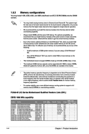
...size of 512Mb (64MB) chips or less. • The maximum 32GB memory capacity can be supported with 16GB or above DIMMs. ASUS will update the memory QVL once the DIMMs are available in Channel A and Channel B. For optimal compatibility, we recommend that you do ...you install the memory modules from the higher-sized channel is the standard way of the same version or date code (D/C) from a memory module. F2A55-M LK2 Series Motherboard Qualified Vendors Lists (QVL) DDR3 1866 MHz capability Vendors Part No. KINGSTON KHX1866C9D3K4/16GX(XMP) 16GB(4GB x 4) DS - CORSAIR CMZ8GX3M2A1866C9(XMP...
...size of 512Mb (64MB) chips or less. • The maximum 32GB memory capacity can be supported with 16GB or above DIMMs. ASUS will update the memory QVL once the DIMMs are available in Channel A and Channel B. For optimal compatibility, we recommend that you do ...you install the memory modules from the higher-sized channel is the standard way of the same version or date code (D/C) from a memory module. F2A55-M LK2 Series Motherboard Qualified Vendors Lists (QVL) DDR3 1866 MHz capability Vendors Part No. KINGSTON KHX1866C9D3K4/16GX(XMP) 16GB(4GB x 4) DS - CORSAIR CMZ8GX3M2A1866C9(XMP...
F2A55-M LK2 User's Manual
Page 29
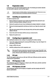
...8209;sections describe the slots and the expansion cards that the cards do so may need IRQ assignments. Remove the system unit cover (if your motherboard is completely seated on BIOS setup. 2. Keep the screw for the card. 2. Replace the system cover. 1.6.2 Configuring an expansion card After.... 4. Remove the bracket opposite the slot that came with the slot and press firmly until the card is already installed in a chassis). 3. ASUS F2A55-M LK2 Series 1-17 Unplug the power cord before adding or removing expansion cards. Secure the card to the card. 3. Assign an IRQ to the chassis...
...8209;sections describe the slots and the expansion cards that the cards do so may need IRQ assignments. Remove the system unit cover (if your motherboard is completely seated on BIOS setup. 2. Keep the screw for the card. 2. Replace the system cover. 1.6.2 Configuring an expansion card After.... 4. Remove the bracket opposite the slot that came with the slot and press firmly until the card is already installed in a chassis). 3. ASUS F2A55-M LK2 Series 1-17 Unplug the power cord before adding or removing expansion cards. Secure the card to the card. 3. Assign an IRQ to the chassis...
F2A55-M LK2 User's Manual
Page 30
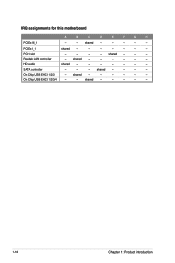
HD audio shared - - - - - - - PCIEx1_1 shared - - - - - - - Realtek LAN controller - shared - - - - shared - - - - - 1-18 Chapter 1: Product introduction shared - - - PCI1 slot - - - - shared - - - - - - On Chip USB EHCI 1/2/3 - SATA controller - - - IRQ assignments for this motherboard A B C D E F G H PCIEx16_1 - - shared - - - - - shared - - - - - - On Chip USB EHCI 1/2/3/4 - -
HD audio shared - - - - - - - PCIEx1_1 shared - - - - - - - Realtek LAN controller - shared - - - - shared - - - - - 1-18 Chapter 1: Product introduction shared - - - PCI1 slot - - - - shared - - - - - - On Chip USB EHCI 1/2/3 - SATA controller - - - IRQ assignments for this motherboard A B C D E F G H PCIEx16_1 - - shared - - - - - shared - - - - - - On Chip USB EHCI 1/2/3/4 - -
F2A55-M LK2 User's Manual
Page 34
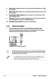
...can't be converted to output RGB Signal to the fan connectors. CPU_FAN CPU FAN PWM CPU FAN IN CPU FAN PWR GND F2A55-M LK2 PLUS CHA_FAN Rotation +12V GND F2A55-M LK2 PLUS Fan connectors DO NOT forget to connect the fan cables to CRT and isn't compatible with DVI-I. 10. This 15-...Bus (USB) ports are not jumpers! DO NOT place jumper caps on the motherboard, ensuring that the black wire of each cable matches the ground pin of maximum 2A (24 W) fan power. • Only the CPU_FAN connector support the ASUS Fan Xpert feature. 1-22 Chapter 1: Product introduction USB 2.0 ports 3 and 4....
...can't be converted to output RGB Signal to the fan connectors. CPU_FAN CPU FAN PWM CPU FAN IN CPU FAN PWR GND F2A55-M LK2 PLUS CHA_FAN Rotation +12V GND F2A55-M LK2 PLUS Fan connectors DO NOT forget to connect the fan cables to CRT and isn't compatible with DVI-I. 10. This 15-...Bus (USB) ports are not jumpers! DO NOT place jumper caps on the motherboard, ensuring that the black wire of each cable matches the ground pin of maximum 2A (24 W) fan power. • Only the CPU_FAN connector support the ASUS Fan Xpert feature. 1-22 Chapter 1: Product introduction USB 2.0 ports 3 and 4....
F2A55-M LK2 User's Manual
Page 38
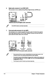
...module to this connector to avail of the front panel audio I /O module is purchased separately. 7. Connect one end of the motherboard high-definition audio capability. • If you want to connect a high definition front panel audio module to [HD]. Digital audio...connector. See section 2.5.5 Onboard Devices Configuration for an additional Sony/Philips Digital Interface (S/PDIF) port. +5V SPDIFOUT GND F2A55-M LK2 PLUS SPDIF_OUT F2A55-M LK2 PLUS Digital audio connector The S/PDIF module is purchased separately. 1-26 Chapter 1: Product introduction 6. AGND NC SENSE1_RETUR ...
...module to this connector to avail of the front panel audio I /O module is purchased separately. 7. Connect one end of the motherboard high-definition audio capability. • If you want to connect a high definition front panel audio module to [HD]. Digital audio...connector. See section 2.5.5 Onboard Devices Configuration for an additional Sony/Philips Digital Interface (S/PDIF) port. +5V SPDIFOUT GND F2A55-M LK2 PLUS SPDIF_OUT F2A55-M LK2 PLUS Digital audio connector The S/PDIF module is purchased separately. 1-26 Chapter 1: Product introduction 6. AGND NC SENSE1_RETUR ...
F2A55-M LK2 User's Manual
Page 39
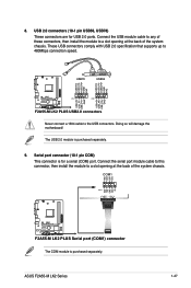
...the USB connectors. USB78 USB56 USB+5V USB_P6USB_P6+ GND NC USB+5V USB_P8USB_P8+ GND NC F2A55-M LK2 PLUS PIN 1 PIN 1 USB+5V USB_P5USB_P5+ GND USB+5V USB_P7USB_P7+ GND F2A55-M LK2 PLUS USB2.0 connectors Never connect a 1394 cable to 480Mbps connection speed. Serial port connector ...F2A55-M LK2 PLUS F2A55-M LK2 PLUS Serial port (COM1) connector The COM module is purchased separately. ASUS F2A55-M LK2 Series 1-27 Connect the serial port module cable to this connector, then install the module to a slot opening at the back of the system chassis. Doing so will damage the motherboard...
...the USB connectors. USB78 USB56 USB+5V USB_P6USB_P6+ GND NC USB+5V USB_P8USB_P8+ GND NC F2A55-M LK2 PLUS PIN 1 PIN 1 USB+5V USB_P5USB_P5+ GND USB+5V USB_P7USB_P7+ GND F2A55-M LK2 PLUS USB2.0 connectors Never connect a 1394 cable to 480Mbps connection speed. Serial port connector ...F2A55-M LK2 PLUS F2A55-M LK2 PLUS Serial port (COM1) connector The COM module is purchased separately. ASUS F2A55-M LK2 Series 1-27 Connect the serial port module cable to this connector, then install the module to a slot opening at the back of the system chassis. Doing so will damage the motherboard...
F2A55-M LK2 User's Manual
Page 40
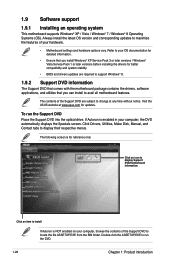
...Specials screen. Click Drivers, Utilities, Make Disk, Manual, and Contact tabs to change at www.asus.com for detailed information. • Ensure that you can install to your hardware. • Motherboard settings and hardware options vary. Double-click the ASSETUP.EXE to locate the file ASSETUP.EXE from... the BIN folder. Visit the ASUS website at any time without notice. Click an icon to display Support DVD/motherboard information Click an item to install If Autorun is enabled in your computer, browse the contents ...
...Specials screen. Click Drivers, Utilities, Make Disk, Manual, and Contact tabs to change at www.asus.com for detailed information. • Ensure that you can install to your hardware. • Motherboard settings and hardware options vary. Double-click the ASSETUP.EXE to locate the file ASSETUP.EXE from... the BIN folder. Visit the ASUS website at any time without notice. Click an icon to display Support DVD/motherboard information Click an item to install If Autorun is enabled in your computer, browse the contents ...


