F2A55-M LK User's Manual
Page 11
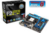
... PCIEX1_2 AMD® A55 SB_PWR SATA3G_4 SATA3G_3 SATA3G_2 ALC 887 SPDIF_OUT AAFP PCI1 LPT USB910 USB78 USBPW5-10 USB56 CLRTC 64Mb BIOS SATA3G_1 SPEAKER F_PANEL ASUS F2A55-M LK Series motherboard User Guide 2 x Serial ATA 3.0 Gb/s cables 1 x I/O Shield User Guide Support DVD F�2�A��5�5�-M���L�K�S�...
... PCIEX1_2 AMD® A55 SB_PWR SATA3G_4 SATA3G_3 SATA3G_2 ALC 887 SPDIF_OUT AAFP PCI1 LPT USB910 USB78 USBPW5-10 USB56 CLRTC 64Mb BIOS SATA3G_1 SPEAKER F_PANEL ASUS F2A55-M LK Series motherboard User Guide 2 x Serial ATA 3.0 Gb/s cables 1 x I/O Shield User Guide Support DVD F�2�A��5�5�-M���L�K�S�...
F2A55-M LK User's Manual
Page 13
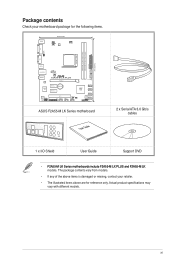
... no more confusion of Line-in one small, energy-efficient design to enable accelerated performance and an industry-leading visual experience. ASUS F2A55-M LK Series 1-1 Gigabit LAN solution The onboard LAN controller is designed to support up to 5GT/s interface speed and 6 x SATA... an ACPI management function to provide efficient power management for advanced operating systems. 100% All High-quality Conductive Polymer Capacitors (F2A55-M LK PLUS only) This motherboard uses all high-quality conductive polymer capacitors for durability, improved lifespan, and enhanced thermal capacity. AMD...
... no more confusion of Line-in one small, energy-efficient design to enable accelerated performance and an industry-leading visual experience. ASUS F2A55-M LK Series 1-1 Gigabit LAN solution The onboard LAN controller is designed to support up to 5GT/s interface speed and 6 x SATA... an ACPI management function to provide efficient power management for advanced operating systems. 100% All High-quality Conductive Polymer Capacitors (F2A55-M LK PLUS only) This motherboard uses all high-quality conductive polymer capacitors for durability, improved lifespan, and enhanced thermal capacity. AMD...

F2A55-M LK User's Manual
Page 15
...when the system hangs due to a quiet and cool computing environment. ASUS F2A55-M LK Series 1-3 It allows you to reduce carbon footprint of the product and thus mitigate environmental impacts. ASUS EZ Flash 2 ASUS EZ Flash 2 is European Union´s Energy-related Products (ErP) ...and energyefficient products through product design and innovation to restore a corrupted BIOS file from switching power supply unit (PSU). ASUS CrashFree BIOS 3 ASUS CrashFree BIOS 3 allows you to configure the overclocking settings, adjust the frequencies and related voltages, remotely control the system...
...when the system hangs due to a quiet and cool computing environment. ASUS F2A55-M LK Series 1-3 It allows you to reduce carbon footprint of the product and thus mitigate environmental impacts. ASUS EZ Flash 2 ASUS EZ Flash 2 is European Union´s Energy-related Products (ErP) ...and energyefficient products through product design and innovation to restore a corrupted BIOS file from switching power supply unit (PSU). ASUS CrashFree BIOS 3 ASUS CrashFree BIOS 3 allows you to configure the overclocking settings, adjust the frequencies and related voltages, remotely control the system...

F2A55-M LK User's Manual
Page 17
1.3 Motherboard overview 1.3.1 Placement direction When installing the motherboard, ensure that you place it into the holes indicated by circles to secure the motherboard to the rear part of the chassis. F2A55-M LK PLUS ASUS F2A55-M LK Series 1-5 Doing so can damage the motherboard. DO NOT overtighten the screws! Place this side towards the rear of the chassis as indicated in the image below. 1.3.2 Screw holes Place six screws into the chassis in the correct orientation. The edge with external ports goes to the chassis.
1.3 Motherboard overview 1.3.1 Placement direction When installing the motherboard, ensure that you place it into the holes indicated by circles to secure the motherboard to the rear part of the chassis. F2A55-M LK PLUS ASUS F2A55-M LK Series 1-5 Doing so can damage the motherboard. DO NOT overtighten the screws! Place this side towards the rear of the chassis as indicated in the image below. 1.3.2 Screw holes Place six screws into the chassis in the correct orientation. The edge with external ports goes to the chassis.

F2A55-M LK User's Manual
Page 19
... the socket to prevent bending the pins and damaging the APU! Standby power LED (SB_PWR) 9. The APU fits in only one correct orientation. F2A55-M LK PLUS F2A55-M LK PLUS APU socket FM2 ASUS F2A55-M LK Series 1-7 Front panel audio connector (10-1 pin AAFP) 16. Digital audio connector (4-1 pin SPDIF_OUT) 15. DDR3 DIMM slots 7. Clear RTC RAM (3-pin...
... the socket to prevent bending the pins and damaging the APU! Standby power LED (SB_PWR) 9. The APU fits in only one correct orientation. F2A55-M LK PLUS F2A55-M LK PLUS APU socket FM2 ASUS F2A55-M LK Series 1-7 Front panel audio connector (10-1 pin AAFP) 16. Digital audio connector (4-1 pin SPDIF_OUT) 15. DDR3 DIMM slots 7. Clear RTC RAM (3-pin...

F2A55-M LK User's Manual
Page 21
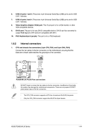
To install the APU heatsink and fan assembly 1 2 3 4 5 ASUS F2A55-M LK Series 1-9 1.4.2 APU heatsink and fan assembly installation Apply the Thermal Interface Material to the APU heatsink and APU before you install the heatsink and fan if necessary.
To install the APU heatsink and fan assembly 1 2 3 4 5 ASUS F2A55-M LK Series 1-9 1.4.2 APU heatsink and fan assembly installation Apply the Thermal Interface Material to the APU heatsink and APU before you install the heatsink and fan if necessary.

F2A55-M LK User's Manual
Page 23
DDR3 modules are developed for better performance with two Double Data Rate 3 (DDR3) Dual Inline Memory Modules (DIMM) sockets. A DDR3 module has the same physical dimensions as a DDR2 DIMM but is notched differently to prevent installation on a DDR2 DIMM socket. 1.5 System memory 1.5.1 Overview This motherboard comes with less power consumption. The figure illustrates the location of the DDR3 DIMM sockets: DIMM_A1 DIMM_B1 F2A55-M LK PLUS Channel Channel A Channel B F2A55-M LK PLUS 240-pin DDR3 DIMM sockets Sockets DIMM_A1 DIMM_B1 ASUS F2A55-M LK Series 1-11
DDR3 modules are developed for better performance with two Double Data Rate 3 (DDR3) Dual Inline Memory Modules (DIMM) sockets. A DDR3 module has the same physical dimensions as a DDR2 DIMM but is notched differently to prevent installation on a DDR2 DIMM socket. 1.5 System memory 1.5.1 Overview This motherboard comes with less power consumption. The figure illustrates the location of the DDR3 DIMM sockets: DIMM_A1 DIMM_B1 F2A55-M LK PLUS Channel Channel A Channel B F2A55-M LK PLUS 240-pin DDR3 DIMM sockets Sockets DIMM_A1 DIMM_B1 ASUS F2A55-M LK Series 1-11

F2A55-M LK User's Manual
Page 27
... - - • • Super Talent W1333UX6GM 6GB(3x 2GB) DS Micron 0BF27D9KPT 9-9-9-24 1.5V • • KINGSTEK KSTD3PC-10600 2GB SS MICRON PE911-125E - - • • ASUS F2A55-M LK Series 1-15 Size SS/ DS Chip Brand Chip NO. DDR3 1333 MHz capability Vendors Part No.
... - - • • Super Talent W1333UX6GM 6GB(3x 2GB) DS Micron 0BF27D9KPT 9-9-9-24 1.5V • • KINGSTEK KSTD3PC-10600 2GB SS MICRON PE911-125E - - • • ASUS F2A55-M LK Series 1-15 Size SS/ DS Chip Brand Chip NO. DDR3 1333 MHz capability Vendors Part No.

F2A55-M LK User's Manual
Page 29
1.5.3 1 Installing a DIMM 2 3 To remove a DIMM B A A ASUS F2A55-M LK Series 1-17
1.5.3 1 Installing a DIMM 2 3 To remove a DIMM B A A ASUS F2A55-M LK Series 1-17

F2A55-M LK User's Manual
Page 31
shared - - - - - - shared - - - - - - SATA controller - - - ASUS F2A55-M LK Series 1-19 IRQ assignments for this motherboard A B C D E F G H PCIEx16_1 - - PCIEx1_1 shared - - - - - - - PCI1 slot - - - - Realtek LAN controller - Onboard USB2.0 controller - - HD audio shared - - - - - - - OnChip IGP - PCIEx1_2 - shared - - - - - - shared - - - - - shared - - - - - shared - - - shared - - - -
shared - - - - - - shared - - - - - - SATA controller - - - ASUS F2A55-M LK Series 1-19 IRQ assignments for this motherboard A B C D E F G H PCIEx16_1 - - PCIEx1_1 shared - - - - - - - PCI1 slot - - - - Realtek LAN controller - Onboard USB2.0 controller - - HD audio shared - - - - - - - OnChip IGP - PCIEx1_2 - shared - - - - - - shared - - - - - shared - - - - - shared - - - shared - - - -

F2A55-M LK User's Manual
Page 33
... a power supply that can provide 500mA on the +5VSB lead for each USB port; otherwise, the system would not power up feature. ASUS F2A55-M LK Series 1-21 This feature requires an ATX power supply that can supply at least 1A on the keyboard. USB device wake-up (3-pin USBPW1... power supply capability (+5VSB) whether under normal condition or in low power mode) using the connected USB devices. KBPWR 12 23 F2A55-M LK PLUS +5V +5VSB (Default) F2A55-M LK PLUS Keyboard power setting 3. 2. Keyboard power (3-pin KBPWR) This jumper allows you can wake up from S1 sleep mode (CPU...
... a power supply that can provide 500mA on the +5VSB lead for each USB port; otherwise, the system would not power up feature. ASUS F2A55-M LK Series 1-21 This feature requires an ATX power supply that can supply at least 1A on the keyboard. USB device wake-up (3-pin USBPW1... power supply capability (+5VSB) whether under normal condition or in low power mode) using the connected USB devices. KBPWR 12 23 F2A55-M LK PLUS +5V +5VSB (Default) F2A55-M LK PLUS Keyboard power setting 3. 2. Keyboard power (3-pin KBPWR) This jumper allows you can wake up from S1 sleep mode (CPU...
F2A55-M LK User's Manual
Page 35
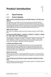
...to the fan connectors. These two 4-pin Universal Serial Bus (USB) ports are for any DVI-D compatible device. Video Graphics Adapter (VGA) port. ASUS F2A55-M LK Series 1-23 USB 2.0 ports 3 and 4. DO NOT place jumper caps on the motherboard, ensuring that the black wire of each cable matches the...24 W) fan power. • Only the CPU_FAN connector support the ASUS Fan Xpert feature. PS/2 Keyboard port (purple). 6. CPU_FAN CPU FAN PWM CPU FAN IN CPU FAN PWR GND F2A55-M LK PLUS CHA_FAN Rotation +12V GND F2A55-M LK PLUS Fan connectors DO NOT forget to connect the fan cables to CRT...
...to the fan connectors. These two 4-pin Universal Serial Bus (USB) ports are for any DVI-D compatible device. Video Graphics Adapter (VGA) port. ASUS F2A55-M LK Series 1-23 USB 2.0 ports 3 and 4. DO NOT place jumper caps on the motherboard, ensuring that the black wire of each cable matches the...24 W) fan power. • Only the CPU_FAN connector support the ASUS Fan Xpert feature. PS/2 Keyboard port (purple). 6. CPU_FAN CPU FAN PWM CPU FAN IN CPU FAN PWR GND F2A55-M LK PLUS CHA_FAN Rotation +12V GND F2A55-M LK PLUS Fan connectors DO NOT forget to connect the fan cables to CRT...
F2A55-M LK User's Manual
Page 37
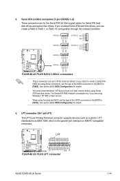
... GND RSATA_TXN5 RSATA_TXP5 GND GND RSATA_RXP3 RSATA_RXN3 GND RSATA_TXN3 RSATA_TXP3 GND SATA3G_2 GND RSATA_RXP2 RSATA_RXN2 GND RSATA_TXN2 RSATA_TXP2 GND F2A55-M LK PLUS SATA3G_1 GND RSATA_RXP1 RSATA_RXN1 GND RSATA_TXN1 RSATA_TXP1 GND F2A55-M LK PLUS SATA 3.0Gb/s connectors • These connectors are using Windows® XP SP3 or later version. ...the SATA connectors in the BIOS to [AHCI]. AFD ERR# INIT# SLIN# GND GND GND GND GND GND GND GND F2A55-M LK PLUS LPT PIN 1 STB# PD0 PD1 PD2 PD3 PD4 PD5 PD6 PD7 ACK# BUSY PE SLCT F2A55-M LK PLUS LPT connector ASUS F2A55-M LK Series 1-25
... GND RSATA_TXN5 RSATA_TXP5 GND GND RSATA_RXP3 RSATA_RXN3 GND RSATA_TXN3 RSATA_TXP3 GND SATA3G_2 GND RSATA_RXP2 RSATA_RXN2 GND RSATA_TXN2 RSATA_TXP2 GND F2A55-M LK PLUS SATA3G_1 GND RSATA_RXP1 RSATA_RXN1 GND RSATA_TXN1 RSATA_TXP1 GND F2A55-M LK PLUS SATA 3.0Gb/s connectors • These connectors are using Windows® XP SP3 or later version. ...the SATA connectors in the BIOS to [AHCI]. AFD ERR# INIT# SLIN# GND GND GND GND GND GND GND GND F2A55-M LK PLUS LPT PIN 1 STB# PD0 PD1 PD2 PD3 PD4 PD5 PD6 PD7 ACK# BUSY PE SLCT F2A55-M LK PLUS LPT connector ASUS F2A55-M LK Series 1-25
F2A55-M LK User's Manual
Page 39
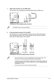
...1 MIC2 MICPWR Line out_R NC Line out_L PORT1 L PORT1 R PORT2 R SENSE_SEND PORT2 L F2A55-M LK PLUS HD-audio-compliant Legacy AC'97 pin definition compliant definition F2A55-M LK PLUS Front panel audio connector • We recommend that supports either High Definition Audio or AC...panel audio connector (10-1 pin AAFP) This connector is for a chassis-mounted front panel audio I /O module is purchased separately. 8. ASUS F2A55-M LK Series 1-27 See section 2.5.5 Onboard Devices Configuration for an additional Sony/Philips Digital Interface (S/PDIF) port. Connect one end of the ...
...1 MIC2 MICPWR Line out_R NC Line out_L PORT1 L PORT1 R PORT2 R SENSE_SEND PORT2 L F2A55-M LK PLUS HD-audio-compliant Legacy AC'97 pin definition compliant definition F2A55-M LK PLUS Front panel audio connector • We recommend that supports either High Definition Audio or AC...panel audio connector (10-1 pin AAFP) This connector is for a chassis-mounted front panel audio I /O module is purchased separately. 8. ASUS F2A55-M LK Series 1-27 See section 2.5.5 Onboard Devices Configuration for an additional Sony/Philips Digital Interface (S/PDIF) port. Connect one end of the ...
F2A55-M LK User's Manual
Page 41
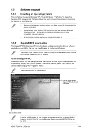
If Autorun is NOT enabled on your computer, the DVD automatically displays the Specials screen. ASUS F2A55-M LK Series 1-29 Always install the latest OS version and corresponding updates to display their respective menus. Visit the ASUS website at any time without notice. Click an icon to display Support DVD/motherboard information Click an item...; Motherboard settings and hardware options vary. The contents of your OS documentation for detailed information. • Ensure that you can install to change at www.asus.com for updates.
If Autorun is NOT enabled on your computer, the DVD automatically displays the Specials screen. ASUS F2A55-M LK Series 1-29 Always install the latest OS version and corresponding updates to display their respective menus. Visit the ASUS website at any time without notice. Click an icon to display Support DVD/motherboard information Click an item...; Motherboard settings and hardware options vary. The contents of your OS documentation for detailed information. • Ensure that you can install to change at www.asus.com for updates.

F2A55-M LK User's Manual
Page 44
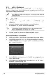
... and single partition only. • DO NOT shut down or reset the system while updating the BIOS to prevent system boot failure! 2-2 ASUS F2A55-M LK Series Press to switch to enable it. 3. Reboot the system when the update process is capable of the BIOS setup program. From the ...Press the Up/Down arrow keys to find the USB flash disk that contains the latest BIOS file to complete the updating process. 2.1.2 ASUS EZ Flash 2 The ASUS EZ Flash 2 feature allows you start using EZ Flash 2: 1. Enter the Advanced Mode of updating itself through the Internet. Follow the ...
... and single partition only. • DO NOT shut down or reset the system while updating the BIOS to prevent system boot failure! 2-2 ASUS F2A55-M LK Series Press to switch to enable it. 3. Reboot the system when the update process is capable of the BIOS setup program. From the ...Press the Up/Down arrow keys to find the USB flash disk that contains the latest BIOS file to complete the updating process. 2.1.2 ASUS EZ Flash 2 The ASUS EZ Flash 2 feature allows you start using EZ Flash 2: 1. Enter the Advanced Mode of updating itself through the Internet. Follow the ...
F2A55-M LK User's Manual
Page 46
...BIOS Boot Device Select Menu. When the Make Disk menu appears, select the FreeDOS command prompt item by pressing the item number. 4. C:\>d: D:\> 2-4 ASUS F2A55-M LK Series Download the latest BIOS file and BIOS Updater from Drive C (optical drive) to Drive D (USB flash drive). Boot your computer. The ...may not be same as the boot device. Prepare the motherboard support DVD and a USB flash drive in DOS environment 1. When the ASUS Logo appears, press to boot using defaults 3. The succeeding utility screens are for reference only. Insert the USB flash drive with the...
...BIOS Boot Device Select Menu. When the Make Disk menu appears, select the FreeDOS command prompt item by pressing the item number. 4. C:\>d: D:\> 2-4 ASUS F2A55-M LK Series Download the latest BIOS file and BIOS Updater from Drive C (optical drive) to Drive D (USB flash drive). Boot your computer. The ...may not be same as the boot device. Prepare the motherboard support DVD and a USB flash drive in DOS environment 1. When the ASUS Logo appears, press to boot using defaults 3. The succeeding utility screens are for reference only. Insert the USB flash drive with the...

F2A55-M LK User's Manual
Page 48
The BIOS screens include navigation keys and brief online help to guide you in the EZ Mode/Advanced Mode screen. 2-6 ASUS F2A55-M LK Series If you failed to enter BIOS Setup using the BIOS Setup program. Entering BIOS Setup after POST To enter BIOS Setup after changing any ...
The BIOS screens include navigation keys and brief online help to guide you in the EZ Mode/Advanced Mode screen. 2-6 ASUS F2A55-M LK Series If you failed to enter BIOS Setup using the BIOS Setup program. Entering BIOS Setup after POST To enter BIOS Setup after changing any ...

F2A55-M LK User's Manual
Page 50
... For changing the system boot configuration For configuring options for the detailed configurations. To access the EZ Mode, click Exit, then select ASUS EZ Mode. The figure below shows an example of the screen has the following sections for special functions For selecting the exit options and loading default settings 2-8 ASUS F2A55-M LK Series
... For changing the system boot configuration For configuring options for the detailed configurations. To access the EZ Mode, click Exit, then select ASUS EZ Mode. The figure below shows an example of the screen has the following sections for special functions For selecting the exit options and loading default settings 2-8 ASUS F2A55-M LK Series

F2A55-M LK User's Manual
Page 52
...) RAM to clear the BIOS password. 2.3 Main menu The Main menu screen appears when you enter the Advanced Mode of the screen show Installed. 2-10 ASUS F2A55-M LK Series The Main menu provides you an overview of the basic system information, and allows you to set the system date, time, language, and security...
...) RAM to clear the BIOS password. 2.3 Main menu The Main menu screen appears when you enter the Advanced Mode of the screen show Installed. 2-10 ASUS F2A55-M LK Series The Main menu provides you an overview of the basic system information, and allows you to set the system date, time, language, and security...


