
F2A55-M LK User's Manual
Page 1
Motherboard F2A55-M LK Series • F2A55-M LK • F2A55-M LK PLUS
Motherboard F2A55-M LK Series • F2A55-M LK • F2A55-M LK PLUS

F2A55-M LK User's Manual
Page 8
... select. If you MUST follow to complete a task IMPORTANT: Instructions that you must press two or more keys simultaneously, the key names are linked with a plus sign (+). Keys enclosed in this guide To ensure that you perform certain tasks properly, take note of the following symbols used in the less-than...
... select. If you MUST follow to complete a task IMPORTANT: Instructions that you must press two or more keys simultaneously, the key names are linked with a plus sign (+). Keys enclosed in this guide To ensure that you perform certain tasks properly, take note of the following symbols used in the less-than...
F2A55-M LK User's Manual
Page 10
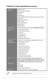
... / switches BIOS Support DVD Form factor ASUS DIGI+ VRM ASUS 3+2 Phase Power Design Network iControl ASUS EPU ASUS AI Suite II ASUS UEFI BIOS EZ Mode featuring friendly graphics user interface ASUS TurboV ASUS Anti-Surge Protection ASUS Fan Xpert ASUS CrashFree BIOS 3 ASUS EZ Flash 2 ASUS MyLogo 2™ 100% All high quality conductive polymer (F2A55-M LK PLUS only) 1 x PS/2 mouse port (green) 1 x PS...
... / switches BIOS Support DVD Form factor ASUS DIGI+ VRM ASUS 3+2 Phase Power Design Network iControl ASUS EPU ASUS AI Suite II ASUS UEFI BIOS EZ Mode featuring friendly graphics user interface ASUS TurboV ASUS Anti-Surge Protection ASUS Fan Xpert ASUS CrashFree BIOS 3 ASUS EZ Flash 2 ASUS MyLogo 2™ 100% All high quality conductive polymer (F2A55-M LK PLUS only) 1 x PS/2 mouse port (green) 1 x PS...
F2A55-M LK User's Manual
Page 11
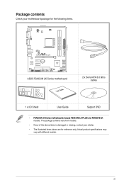
...(9.6in) VGA USB34 LAN_USB12 COM CHA_FAN AUDIO RTL 8111F Super I/O F2A55-M LK PLUS PCIEX16 PCIEX1_1 Lithium Cell CMOS Power PCIEX1_2 AMD® A55 SB_PWR SATA3G_4 SATA3G_3 SATA3G_2 ALC 887 SPDIF_OUT AAFP PCI1 LPT USB910 USB78 USBPW5-10 USB56 CLRTC 64Mb BIOS SATA3G_1 SPEAKER F_PANEL ASUS F2A55-M LK Series motherboard User Guide 2 x Serial ATA 3.0 Gb/s cables 1 x I/O Shield...
...(9.6in) VGA USB34 LAN_USB12 COM CHA_FAN AUDIO RTL 8111F Super I/O F2A55-M LK PLUS PCIEX16 PCIEX1_1 Lithium Cell CMOS Power PCIEX1_2 AMD® A55 SB_PWR SATA3G_4 SATA3G_3 SATA3G_2 ALC 887 SPDIF_OUT AAFP PCI1 LPT USB910 USB78 USBPW5-10 USB56 CLRTC 64Mb BIOS SATA3G_1 SPEAKER F_PANEL ASUS F2A55-M LK Series motherboard User Guide 2 x Serial ATA 3.0 Gb/s cables 1 x I/O Shield...
F2A55-M LK User's Manual
Page 13
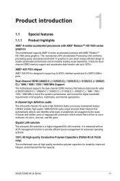
... to provide efficient power management for advanced operating systems. 100% All High-quality Conductive Polymer Capacitors (F2A55-M LK PLUS only) This motherboard uses all high-quality conductive polymer capacitors for durability, improved lifespan, and enhanced thermal capacity. ASUS F2A55-M LK Series 1-1 C.) / 1866 / 1600 / 1333 / 1066 MHz Support The motherboard supports the dual-channel DDR3 memory that...
... to provide efficient power management for advanced operating systems. 100% All High-quality Conductive Polymer Capacitors (F2A55-M LK PLUS only) This motherboard uses all high-quality conductive polymer capacitors for durability, improved lifespan, and enhanced thermal capacity. ASUS F2A55-M LK Series 1-1 C.) / 1866 / 1600 / 1333 / 1066 MHz Support The motherboard supports the dual-channel DDR3 memory that...

F2A55-M LK User's Manual
Page 16
... case, to avoid damaging them due to static electricity. • Hold components by the edges to the motherboard, peripherals, or components. SB_PWR F2A55-M LK PLUS ON OFF Standby Power Powered Off F2A55-M LK PLUS Onboard LED 1-4 Chapter 1: Product introduction The illustration below shows the location of the following precautions before you install motherboard components or change...
... case, to avoid damaging them due to static electricity. • Hold components by the edges to the motherboard, peripherals, or components. SB_PWR F2A55-M LK PLUS ON OFF Standby Power Powered Off F2A55-M LK PLUS Onboard LED 1-4 Chapter 1: Product introduction The illustration below shows the location of the following precautions before you install motherboard components or change...

F2A55-M LK User's Manual
Page 17
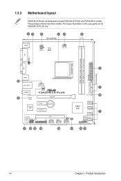
Place this side towards the rear of the chassis as indicated in the image below. 1.3.2 Screw holes Place six screws into the chassis in the correct orientation. Doing so can damage the motherboard. F2A55-M LK PLUS ASUS F2A55-M LK Series 1-5 DO NOT overtighten the screws! The edge with external ports goes to the chassis. 1.3 Motherboard overview 1.3.1 Placement direction When installing the motherboard, ensure that you place it into the holes indicated by circles to secure the motherboard to the rear part of the chassis.
Place this side towards the rear of the chassis as indicated in the image below. 1.3.2 Screw holes Place six screws into the chassis in the correct orientation. Doing so can damage the motherboard. F2A55-M LK PLUS ASUS F2A55-M LK Series 1-5 DO NOT overtighten the screws! The edge with external ports goes to the chassis. 1.3 Motherboard overview 1.3.1 Placement direction When installing the motherboard, ensure that you place it into the holes indicated by circles to secure the motherboard to the rear part of the chassis.
F2A55-M LK User's Manual
Page 18
The package contents vary from models. The layout illustrations in this user guide are for F2A55-M LK PLUS only. 12 3 45 6 20.8cm(8.2in) KBMS ATX12V DIGI +VRM CPU_FAN DVI KBPWR USBPW1-4 SOCKET FM2 DDR3 DIMM_A1 (64bit, 240-pin module) DDR3... DIMM_B1 (64bit, 240-pin module) EATXPWR SATA3G_5 SATA3G_6 24.4cm(9.6in) VGA 3 USB34 16 COM LAN_USB12 CHA_FAN 7 AUDIO 5 RTL 8111F Super I/O F2A55-M LK PLUS PCIEX16 PCIEX1_1 Lithium Cell CMOS Power PCIEX1_2 SB_PWR 8 AMD® A55 SATA3G_4 SATA3G_3 SATA3G_2 7 ALC 887 SPDIF_OUT AAFP PCI1 LPT USB910 USB78 USBPW5-10 USB56...
The package contents vary from models. The layout illustrations in this user guide are for F2A55-M LK PLUS only. 12 3 45 6 20.8cm(8.2in) KBMS ATX12V DIGI +VRM CPU_FAN DVI KBPWR USBPW1-4 SOCKET FM2 DDR3 DIMM_A1 (64bit, 240-pin module) DDR3... DIMM_B1 (64bit, 240-pin module) EATXPWR SATA3G_5 SATA3G_6 24.4cm(9.6in) VGA 3 USB34 16 COM LAN_USB12 CHA_FAN 7 AUDIO 5 RTL 8111F Super I/O F2A55-M LK PLUS PCIEX16 PCIEX1_1 Lithium Cell CMOS Power PCIEX1_2 SB_PWR 8 AMD® A55 SATA3G_4 SATA3G_3 SATA3G_2 7 ALC 887 SPDIF_OUT AAFP PCI1 LPT USB910 USB78 USBPW5-10 USB56...

F2A55-M LK User's Manual
Page 19
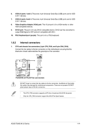
... for the FM2 socket. CPU and chassis fan connectors (4-pin CPU_FAN and 3-pin CHA_FAN) 6. System panel connector (10-1 pin F_PANEL) 10. DDR3 DIMM slots 7. F2A55-M LK PLUS F2A55-M LK PLUS APU socket FM2 ASUS F2A55-M LK Series 1-7 AMD FM2 socket 5. USB 2.0 connectors (10-1 pin USB56, USB78, USB910) 13. LPT connector (26-1 pin LPT) 14. 1.3.4 Layout contents Connectors/Jumpers/Slots...
... for the FM2 socket. CPU and chassis fan connectors (4-pin CPU_FAN and 3-pin CHA_FAN) 6. System panel connector (10-1 pin F_PANEL) 10. DDR3 DIMM slots 7. F2A55-M LK PLUS F2A55-M LK PLUS APU socket FM2 ASUS F2A55-M LK Series 1-7 AMD FM2 socket 5. USB 2.0 connectors (10-1 pin USB56, USB78, USB910) 13. LPT connector (26-1 pin LPT) 14. 1.3.4 Layout contents Connectors/Jumpers/Slots...

F2A55-M LK User's Manual
Page 23
The figure illustrates the location of the DDR3 DIMM sockets: DIMM_A1 DIMM_B1 F2A55-M LK PLUS Channel Channel A Channel B F2A55-M LK PLUS 240-pin DDR3 DIMM sockets Sockets DIMM_A1 DIMM_B1 ASUS F2A55-M LK Series 1-11 DDR3 modules are developed for better performance with two Double Data Rate 3 (DDR3) Dual Inline Memory Modules (DIMM) sockets. A DDR3 module has the same physical dimensions as a DDR2 DIMM but is notched differently to prevent installation on a DDR2 DIMM socket. 1.5 System memory 1.5.1 Overview This motherboard comes with less power consumption.
The figure illustrates the location of the DDR3 DIMM sockets: DIMM_A1 DIMM_B1 F2A55-M LK PLUS Channel Channel A Channel B F2A55-M LK PLUS 240-pin DDR3 DIMM sockets Sockets DIMM_A1 DIMM_B1 ASUS F2A55-M LK Series 1-11 DDR3 modules are developed for better performance with two Double Data Rate 3 (DDR3) Dual Inline Memory Modules (DIMM) sockets. A DDR3 module has the same physical dimensions as a DDR2 DIMM but is notched differently to prevent installation on a DDR2 DIMM socket. 1.5 System memory 1.5.1 Overview This motherboard comes with less power consumption.
F2A55-M LK User's Manual
Page 32
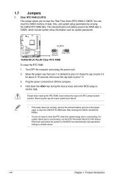
... clear the RTC when the system hangs due to reenter data. The onboard button cell battery powers the RAM data in CMOS. F2A55-M LK PLUS CLRTC 12 23 Normal (Default) Clear RTC F2A55-M LK PLUS Clear RTC RAM To erase the RTC RAM: 1. For system failure due to pins 1-2. 3. Turn OFF the computer and unplug the...
... clear the RTC when the system hangs due to reenter data. The onboard button cell battery powers the RAM data in CMOS. F2A55-M LK PLUS CLRTC 12 23 Normal (Default) Clear RTC F2A55-M LK PLUS Clear RTC RAM To erase the RTC RAM: 1. For system failure due to pins 1-2. 3. Turn OFF the computer and unplug the...

F2A55-M LK User's Manual
Page 33
KBPWR 12 23 F2A55-M LK PLUS +5V +5VSB (Default) F2A55-M LK PLUS Keyboard power setting 3. USBPW1-4 12 23 +5V +5VSB (Default) F2A55-M LK PLUS USBPW5-10 12 23 +5V +5VSB (Default) F2A55-M LK PLUS USB device wake-up • The USB device wake-up feature requires a power supply that can supply at least 1A ... KBPWR) This jumper allows you to CPU, DRAM in slow refresh, power supply in low power mode) using the connected USB devices. ASUS F2A55-M LK Series 1-21 Set to +5VSB to wake up feature. When you can provide 500mA on the keyboard. otherwise, the system would not ...
KBPWR 12 23 F2A55-M LK PLUS +5V +5VSB (Default) F2A55-M LK PLUS Keyboard power setting 3. USBPW1-4 12 23 +5V +5VSB (Default) F2A55-M LK PLUS USBPW5-10 12 23 +5V +5VSB (Default) F2A55-M LK PLUS USB device wake-up • The USB device wake-up feature requires a power supply that can supply at least 1A ... KBPWR) This jumper allows you to CPU, DRAM in slow refresh, power supply in low power mode) using the connected USB devices. ASUS F2A55-M LK Series 1-21 Set to +5VSB to wake up feature. When you can provide 500mA on the keyboard. otherwise, the system would not ...
F2A55-M LK User's Manual
Page 35
DVI-D can't be converted to output RGB Signal to the fan connectors. Insufficient air flow inside the system may damage the motherboard components. ASUS F2A55-M LK Series 1-23 USB 2.0 ports 3 and 4. This port is for any DVI-D compatible device. This port is for a VGA monitor or ...8226; The CPU_FAN connector supports a CPU fan of the connector. CPU_FAN CPU FAN PWM CPU FAN IN CPU FAN PWR GND F2A55-M LK PLUS CHA_FAN Rotation +12V GND F2A55-M LK PLUS Fan connectors DO NOT forget to connect the fan cables to CRT and isn't compatible with DVI-I. 10. Video Graphics Adapter...
DVI-D can't be converted to output RGB Signal to the fan connectors. Insufficient air flow inside the system may damage the motherboard components. ASUS F2A55-M LK Series 1-23 USB 2.0 ports 3 and 4. This port is for any DVI-D compatible device. This port is for a VGA monitor or ...8226; The CPU_FAN connector supports a CPU fan of the connector. CPU_FAN CPU FAN PWM CPU FAN IN CPU FAN PWR GND F2A55-M LK PLUS CHA_FAN Rotation +12V GND F2A55-M LK PLUS Fan connectors DO NOT forget to connect the fan cables to CRT and isn't compatible with DVI-I. 10. Video Graphics Adapter...

F2A55-M LK User's Manual
Page 36
..., refer to install additional devices. The plugs from the power supply are designed to connect the 4-pin ATX +12V power plug. ATX12V EATXPWR GND GND F2A55-M LK PLUS +3 Volts PIN 1 +12 Volts +12 Volts +5V Standby Power OK +12V DC +12V DC GND +5 Volts GND +5 Volts GND +3 Volts +3 Volts PIN... that you intend to use a PSU with 20-pin and 4-pin power plugs, ensure that the 20-pin power plug can provide at http://support.asus. The system may become unstable or may not boot up if the power is inadequate. • If you intend to the Recommended Power Supply Wattage...
..., refer to install additional devices. The plugs from the power supply are designed to connect the 4-pin ATX +12V power plug. ATX12V EATXPWR GND GND F2A55-M LK PLUS +3 Volts PIN 1 +12 Volts +12 Volts +5V Standby Power OK +12V DC +12V DC GND +5 Volts GND +5 Volts GND +3 Volts +3 Volts PIN... that you intend to use a PSU with 20-pin and 4-pin power plugs, ensure that the 20-pin power plug can provide at http://support.asus. The system may become unstable or may not boot up if the power is inadequate. • If you intend to the Recommended Power Supply Wattage...
F2A55-M LK User's Manual
Page 37
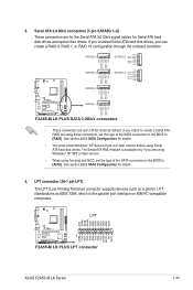
...RSATA_TXP5 GND GND RSATA_RXP3 RSATA_RXN3 GND RSATA_TXN3 RSATA_TXP3 GND SATA3G_2 GND RSATA_RXP2 RSATA_RXN2 GND RSATA_TXN2 RSATA_TXP2 GND F2A55-M LK PLUS SATA3G_1 GND RSATA_RXP1 RSATA_RXN1 GND RSATA_TXN1 RSATA_TXP1 GND F2A55-M LK PLUS SATA 3.0Gb/s connectors • These connectors are using Windows® XP SP3 or later ...AFD ERR# INIT# SLIN# GND GND GND GND GND GND GND GND F2A55-M LK PLUS LPT PIN 1 STB# PD0 PD1 PD2 PD3 PD4 PD5 PD6 PD7 ACK# BUSY PE SLCT F2A55-M LK PLUS LPT connector ASUS F2A55-M LK Series 1-25 Serial ATA 3.0 Gb/s connectors (7-pin SATA3G 1~6) These connectors ...
...RSATA_TXP5 GND GND RSATA_RXP3 RSATA_RXN3 GND RSATA_TXN3 RSATA_TXP3 GND SATA3G_2 GND RSATA_RXP2 RSATA_RXN2 GND RSATA_TXN2 RSATA_TXP2 GND F2A55-M LK PLUS SATA3G_1 GND RSATA_RXP1 RSATA_RXN1 GND RSATA_TXN1 RSATA_TXP1 GND F2A55-M LK PLUS SATA 3.0Gb/s connectors • These connectors are using Windows® XP SP3 or later ...AFD ERR# INIT# SLIN# GND GND GND GND GND GND GND GND F2A55-M LK PLUS LPT PIN 1 STB# PD0 PD1 PD2 PD3 PD4 PD5 PD6 PD7 ACK# BUSY PE SLCT F2A55-M LK PLUS LPT connector ASUS F2A55-M LK Series 1-25 Serial ATA 3.0 Gb/s connectors (7-pin SATA3G 1~6) These connectors ...
F2A55-M LK User's Manual
Page 38
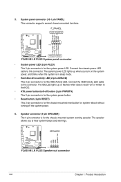
... or flashes when data is read from or written to hear system beeps and warnings. +5V GND GND Speaker Out SPEAKER F2A55-M LK PLUS PIN 1 F2A55-M LK PLUS Speaker out connector 1-26 Chapter 1: Product introduction System panel connector (10-1 pin PANEL) This connector supports several chassis-mounted ... LED lights up when you to the HDD. • ATX power button/soft-off the system power. 6. Ground Reset F2A55-M LK PLUS PIN 1 +HDLED RESET F2A55-M LK PLUS System panel connector • System power LED (2-pin PLED) This 2-pin connector is for the chassis-mounted system warning speaker...
... or flashes when data is read from or written to hear system beeps and warnings. +5V GND GND Speaker Out SPEAKER F2A55-M LK PLUS PIN 1 F2A55-M LK PLUS Speaker out connector 1-26 Chapter 1: Product introduction System panel connector (10-1 pin PANEL) This connector supports several chassis-mounted ... LED lights up when you to the HDD. • ATX power button/soft-off the system power. 6. Ground Reset F2A55-M LK PLUS PIN 1 +HDLED RESET F2A55-M LK PLUS System panel connector • System power LED (2-pin PLED) This 2-pin connector is for the chassis-mounted system warning speaker...
F2A55-M LK User's Manual
Page 39
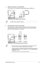
... to this connector, set the Front Panel Type item in the BIOS to [HD]. F2A55-M LK PLUS SPDIF_OUT F2A55-M LK PLUS Digital audio connector The S/PDIF module is for details. • The front panel audio I /O module cable to this connector to this connector. ASUS F2A55-M LK Series 1-27 AGND NC SENSE1_RETUR SENSE2_RETUR AGND NC NC NC AAFP PIN 1 MIC2...
... to this connector, set the Front Panel Type item in the BIOS to [HD]. F2A55-M LK PLUS SPDIF_OUT F2A55-M LK PLUS Digital audio connector The S/PDIF module is for details. • The front panel audio I /O module cable to this connector to this connector. ASUS F2A55-M LK Series 1-27 AGND NC SENSE1_RETUR SENSE2_RETUR AGND NC NC NC AAFP PIN 1 MIC2...

F2A55-M LK User's Manual
Page 40
...+ GND NC USB+5V USB_P6USB_P6+ GND NC USB+5V USB_P9USB_P9+ GND USB+5V USB_P7USB_P7+ GND USB+5V USB_P5USB_P5+ GND F2A55-M LK PLUS PIN 1 PIN 1 PIN 1 F2A55-M LK PLUS USB2.0 connectors Never connect a 1394 cable to 480Mbps connection speed. The USB 2.0 module is purchased separately. 1-28 Chapter... 1: Product introduction COM RXD DTR DSR CTS PIN 1 DCD TXD GND RTS RI F2A55-M LK PLUS F2A55-M LK PLUS Serial port (COM) connector The COM module is purchased separately. 10. Connect the USB module cable to any of these connectors...
...+ GND NC USB+5V USB_P6USB_P6+ GND NC USB+5V USB_P9USB_P9+ GND USB+5V USB_P7USB_P7+ GND USB+5V USB_P5USB_P5+ GND F2A55-M LK PLUS PIN 1 PIN 1 PIN 1 F2A55-M LK PLUS USB2.0 connectors Never connect a 1394 cable to 480Mbps connection speed. The USB 2.0 module is purchased separately. 1-28 Chapter... 1: Product introduction COM RXD DTR DSR CTS PIN 1 DCD TXD GND RTS RI F2A55-M LK PLUS F2A55-M LK PLUS Serial port (COM) connector The COM module is purchased separately. 10. Connect the USB module cable to any of these connectors...
F2A55-M LK User's Manual
Page 45
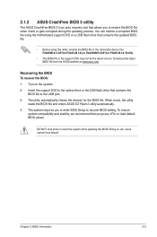
... contains the BIOS file to load default BIOS values. 2.1.3 ASUS CrashFree BIOS 3 utility The ASUS CrashFree BIOS 3 is an auto recovery tool that allows you to recover BIOS setting. The utility automatically checks the devices for F2A55-M LK PLUS). • The BIOS file in the removable device into ...F2A55MLK.CAP (for F2A55-M LK) or F2A55MKP.CAP (for the BIOS file....
... contains the BIOS file to load default BIOS values. 2.1.3 ASUS CrashFree BIOS 3 utility The ASUS CrashFree BIOS 3 is an auto recovery tool that allows you to recover BIOS setting. The utility automatically checks the devices for F2A55-M LK PLUS). • The BIOS file in the removable device into ...F2A55MLK.CAP (for F2A55-M LK) or F2A55MKP.CAP (for the BIOS file....
F2A55-M LK User's Manual
Page 47
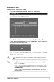
... boot failure! • For BIOS Updater version 1.30 or later, the utility automatically exits to section 2.9 Exit menu for DOS V1.30 Current ROM BOARD: F2A55-M LK PLUS VER: 0301 DATE: 07/13/2012 Update ROM BOARD: Unknown VER: Unknown DATE: Unknown PATH: A:\ A: F2A55MKP.CAP 8390656 2012-07-13 17:30:48 Note...
... boot failure! • For BIOS Updater version 1.30 or later, the utility automatically exits to section 2.9 Exit menu for DOS V1.30 Current ROM BOARD: F2A55-M LK PLUS VER: 0301 DATE: 07/13/2012 Update ROM BOARD: Unknown VER: Unknown DATE: Unknown PATH: A:\ A: F2A55MKP.CAP 8390656 2012-07-13 17:30:48 Note...


