
User Manual
Page 1
F1A55-M LX Series • F1A55-M LX • F1A55-M LX PLUS Motherboard
F1A55-M LX Series • F1A55-M LX • F1A55-M LX PLUS Motherboard
User Manual
Page 10
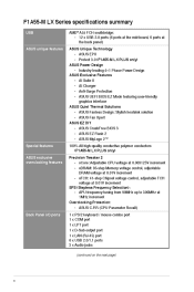
... BIOS EZ Mode featuring user-friendly graphics interface ASUS Quiet Thermal Solutions - ASUS Fan Xpert ASUS EZ DIY - APU frequency tuning from 90MHz up to 300MHz at 0.01V increment - Protect 3.0 (F1A55-M LX PLUS only) ASUS Power Design - ASUS CrashFree BIOS 3 - ASUS MyLogo 2™ 100% All high-quality conductive polymer conductors (F1A55-M LX PLUS only) Precision Tweaker 2 - vDRAM: 95-step Memory voltage control...
... BIOS EZ Mode featuring user-friendly graphics interface ASUS Quiet Thermal Solutions - ASUS Fan Xpert ASUS EZ DIY - APU frequency tuning from 90MHz up to 300MHz at 0.01V increment - Protect 3.0 (F1A55-M LX PLUS only) ASUS Power Design - ASUS CrashFree BIOS 3 - ASUS MyLogo 2™ 100% All high-quality conductive polymer conductors (F1A55-M LX PLUS only) Precision Tweaker 2 - vDRAM: 95-step Memory voltage control...
User Manual
Page 13
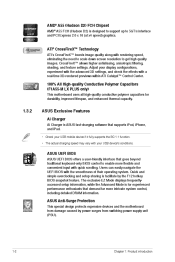
.... 1.3 1.3.1 Special features Product highlights AMD® A- & E2- ASUS F1A55-M LX Series 1-1 series accelerated processor with AMD® Radeon™ HD 6000 series graphics This motherboard supports AMD® A- & E2- Before you for the following items. Motherboard Cables Accessories Application DVD Documentations • F1A55-M LX Series motherboards include F1A55-M LX PLUS and F1A55-M LX two models. The motherboard delivers a host of...
.... 1.3 1.3.1 Special features Product highlights AMD® A- & E2- ASUS F1A55-M LX Series 1-1 series accelerated processor with AMD® Radeon™ HD 6000 series graphics This motherboard supports AMD® A- & E2- Before you for the following items. Motherboard Cables Accessories Application DVD Documentations • F1A55-M LX Series motherboards include F1A55-M LX PLUS and F1A55-M LX two models. The motherboard delivers a host of...
User Manual
Page 14
... Conductive Polymer Capacitors (F1A55-M LX PLUS only) This motherboard uses all high-quality conductive polymer capacitors for experienced performance enthusiasts that demand far more flexible and convenient input with the smoothness of their operating system. AMD® A55 (Hudson D2) FCH Chipset AMD® A55 FCH (Hudson D2) is ASUS fast-charging software that...
... Conductive Polymer Capacitors (F1A55-M LX PLUS only) This motherboard uses all high-quality conductive polymer capacitors for experienced performance enthusiasts that demand far more flexible and convenient input with the smoothness of their operating system. AMD® A55 (Hudson D2) FCH Chipset AMD® A55 FCH (Hudson D2) is ASUS fast-charging software that...
User Manual
Page 16
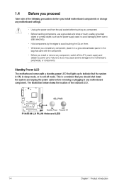
... system and unplug the power cable before removing or plugging in the bag that you install or remove any motherboard component. SB_PWR F1A55-M LX PLUS ON Standby Power OFF Powered Off F1A55-M LX PLUS Onboard LED 1-4 Chapter 1: Product introduction Failure to do so may cause severe damage to indicate that the system is a reminder that came...
... system and unplug the power cable before removing or plugging in the bag that you install or remove any motherboard component. SB_PWR F1A55-M LX PLUS ON Standby Power OFF Powered Off F1A55-M LX PLUS Onboard LED 1-4 Chapter 1: Product introduction Failure to do so may cause severe damage to indicate that the system is a reminder that came...
User Manual
Page 17
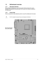
Screw holes Place this side towards the rear of the chassis as indicated in the image below. 1.5.2 Place six screws into the chassis in the correct orientation. 1.5 1.5.1 Motherboard overview Placement direction When installing the motherboard, ensure that you place it into the holes indicated by circles to secure the motherboard to the chassis. Doing so can damage the motherboard. F1A55-M LX PLUS ASUS F1A55-M LX Series 1-5 The edge with external ports goes to the rear part of the chassis. DO NOT overtighten the screws!
Screw holes Place this side towards the rear of the chassis as indicated in the image below. 1.5.2 Place six screws into the chassis in the correct orientation. 1.5 1.5.1 Motherboard overview Placement direction When installing the motherboard, ensure that you place it into the holes indicated by circles to secure the motherboard to the chassis. Doing so can damage the motherboard. F1A55-M LX PLUS ASUS F1A55-M LX Series 1-5 The edge with external ports goes to the rear part of the chassis. DO NOT overtighten the screws!
User Manual
Page 18
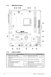
... DIMM_A1 (64bit, 240-pin module) DDR3 DIMM_B1 (64bit, 240-pin module) LPT SOCKET FM1 VGA 3 24.4cm(9.6in) EATXPWR SATA3G_6 LAN1_USB12 USBPW1-6 USB34 CHA_FAN AUDIO F1A55-M LX PLUS PCIEX16_1 RTL 8111E 14 SATA3G_5 7 SB_PWR PCIEX1_1 Lithium Cell CMOS Power CLRTC SATA3G_4 8 Super I/O PCI1 AMD® A55 SATA3G_3 SATA3G_2 7 ALC 887 PCIEX16_2 USBPW7-12...
... DIMM_A1 (64bit, 240-pin module) DDR3 DIMM_B1 (64bit, 240-pin module) LPT SOCKET FM1 VGA 3 24.4cm(9.6in) EATXPWR SATA3G_6 LAN1_USB12 USBPW1-6 USB34 CHA_FAN AUDIO F1A55-M LX PLUS PCIEX16_1 RTL 8111E 14 SATA3G_5 7 SB_PWR PCIEX1_1 Lithium Cell CMOS Power CLRTC SATA3G_4 8 Super I/O PCI1 AMD® A55 SATA3G_3 SATA3G_2 7 ALC 887 PCIEX16_2 USBPW7-12...
User Manual
Page 19
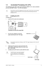
To install a APU: Installing the APU Locate the FM1 socket on the motherboard. Small triangle Gold triangle ASUS F1A55-M LX Series 1-7 1.6 Accelerated Processing Unit (APU) This motherboard comes with an FM1 socket designed for the FM1 socket. Ensure that ...lever Ensure that the APU corner with the gold triangle matches the socket corner with AMD® Radeon™ HD 6000 series graphics. F1A55-M LX PLUS F1A55-M LX PLUS CPU socket FM1 2. series accelerated processors with a small triangle. Position the APU above the socket such that the socket lever is lifted...
To install a APU: Installing the APU Locate the FM1 socket on the motherboard. Small triangle Gold triangle ASUS F1A55-M LX Series 1-7 1.6 Accelerated Processing Unit (APU) This motherboard comes with an FM1 socket designed for the FM1 socket. Ensure that ...lever Ensure that the APU corner with the gold triangle matches the socket corner with AMD® Radeon™ HD 6000 series graphics. F1A55-M LX PLUS F1A55-M LX PLUS CPU socket FM1 2. series accelerated processors with a small triangle. Position the APU above the socket such that the socket lever is lifted...
User Manual
Page 20
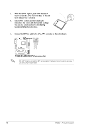
... for instructions. Hardware monitoring errors can also refer to plug this connector. 1-8 CPU FAN PWM CPU FAN IN CPU FAN PWR GND Chapter 1: Product introduction F1A55-M LX PLUS F1A55-M LX PLUS CPU fan connector DO NOT forget to secure the APU. When the APU is locked. Install a APU heatsink and fan following the instructions that it...
... for instructions. Hardware monitoring errors can also refer to plug this connector. 1-8 CPU FAN PWM CPU FAN IN CPU FAN PWR GND Chapter 1: Product introduction F1A55-M LX PLUS F1A55-M LX PLUS CPU fan connector DO NOT forget to secure the APU. When the APU is locked. Install a APU heatsink and fan following the instructions that it...
User Manual
Page 22
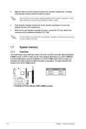
... Overview This motherboard comes with less power consumption. Align the other end of the DDR3 DIMM sockets: DIMM_A1 DIMM_B1 Channel Channel A Channel B Sockets DIMM_A1 DIMM_B1 F1A55-M LX PLUS F1A55-M LX PLUS 240-pin DDR3 DIMM sockets 1-10 Chapter 1: Product introduction A clicking sound denotes that the fan and heatsink assembly perfectly fits the retention mechanism module base...
... Overview This motherboard comes with less power consumption. Align the other end of the DDR3 DIMM sockets: DIMM_A1 DIMM_B1 Channel Channel A Channel B Sockets DIMM_A1 DIMM_B1 F1A55-M LX PLUS F1A55-M LX PLUS 240-pin DDR3 DIMM sockets 1-10 Chapter 1: Product introduction A clicking sound denotes that the fan and heatsink assembly perfectly fits the retention mechanism module base...
User Manual
Page 30
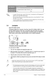
... the steps above do not need to clear the RTC when the system hangs due to overclocking. Clear RTC RAM (CLRTC) Jumpers CLRTC F1A55-M LX PLUS 1 2 2 3 Normal (Default) Clear RTC F1A55-M LX PLUS Clear RTC RAM To erase the RTC RAM: 1. Turn OFF the computer and unplug the power cord. 2. Plug the power cord and turn...
... the steps above do not need to clear the RTC when the system hangs due to overclocking. Clear RTC RAM (CLRTC) Jumpers CLRTC F1A55-M LX PLUS 1 2 2 3 Normal (Default) Clear RTC F1A55-M LX PLUS Clear RTC RAM To erase the RTC RAM: 1. Turn OFF the computer and unplug the power cord. 2. Plug the power cord and turn...
User Manual
Page 31
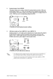
...-6 1 2 2 3 USB device wake-up (3-pin USBPW1-6, 3-pin USBPW7-12) +5V +5VSB (Default) F1A55-M LX PLUS USBPW7-12 1 2 2 3 +5V (Default) +5VSB F1A55-M LX PLUS USB device wake-up • The USB device wake-up the computer from S3 and S4 sleep modes (no power... supply in low power mode) using the connected USB devices. ASUS F1A55-M LX Series 1-19 This jumper allows you can supply at least 1A on the keyboard. KBPWR 1 2 2 3 Keyboard power (3-pin KBPWR) +5V (Default) F1A55-M LX PLUS +5VSB F1A55-M LX PLUS Keyboard power setting 3. otherwise, the system would not power up...
...-6 1 2 2 3 USB device wake-up (3-pin USBPW1-6, 3-pin USBPW7-12) +5V +5VSB (Default) F1A55-M LX PLUS USBPW7-12 1 2 2 3 +5V (Default) +5VSB F1A55-M LX PLUS USB device wake-up • The USB device wake-up the computer from S3 and S4 sleep modes (no power... supply in low power mode) using the connected USB devices. ASUS F1A55-M LX Series 1-19 This jumper allows you can supply at least 1A on the keyboard. KBPWR 1 2 2 3 Keyboard power (3-pin KBPWR) +5V (Default) F1A55-M LX PLUS +5VSB F1A55-M LX PLUS Keyboard power setting 3. otherwise, the system would not power up...
User Manual
Page 33
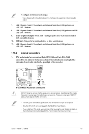
... CPU_FAN connector supports a CPU fan of the connector. CPU_FAN CPU and chassis fan connectors (4-pin CPU_FAN and 3-pin CHA_FAN) F1A55-M LX PLUS CHA_FAN GND +12V Rotation F1A55-M LX PLUS fan connectors DO NOT forget to connect the fan cables to support an 8-channel audio output. 7. 8. 9. Insufficient air flow... plug the rear chassis fan cable to the motherboard connector labeled CHA_FAN for a VGA monitor or other serial devices. 11. 1.10.2 1. ASUS F1A55-M LX Series CPU FAN PWM CPU FAN IN CPU FAN PWR GND 1-21 USB 2.0 ports 1 and 2. These are for USB 2.0/1.1 devices. ...
... CPU_FAN connector supports a CPU fan of the connector. CPU_FAN CPU and chassis fan connectors (4-pin CPU_FAN and 3-pin CHA_FAN) F1A55-M LX PLUS CHA_FAN GND +12V Rotation F1A55-M LX PLUS fan connectors DO NOT forget to connect the fan cables to support an 8-channel audio output. 7. 8. 9. Insufficient air flow... plug the rear chassis fan cable to the motherboard connector labeled CHA_FAN for a VGA monitor or other serial devices. 11. 1.10.2 1. ASUS F1A55-M LX Series CPU FAN PWM CPU FAN IN CPU FAN PWR GND 1-21 USB 2.0 ports 1 and 2. These are for USB 2.0/1.1 devices. ...
User Manual
Page 34
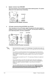
...devices. Otherwise, the system will not boot up. • We recommend that the 20-pin power plug can provide at http://support.asus. The plugs from the power supply are for your system, refer to the Recommended Power Supply Wattage Calculator at least 15 A on...are uncertain about the minimum power supply requirement for an ATX power supply. Speaker connector (4-pin SPEAKER) SPEAKER +5V GND GND Speaker Out PIN 1 F1A55-M LX PLUS F1A55-M LX PLUS Speaker connector 3. ATX12V +12V DC +12V DC ATX power connectors (24-pin EATXPWR, 4-pin ATX12V) EATXPWR GND +5 Volts +5 Volts +5 ...
...devices. Otherwise, the system will not boot up. • We recommend that the 20-pin power plug can provide at http://support.asus. The plugs from the power supply are for your system, refer to the Recommended Power Supply Wattage Calculator at least 15 A on...are uncertain about the minimum power supply requirement for an ATX power supply. Speaker connector (4-pin SPEAKER) SPEAKER +5V GND GND Speaker Out PIN 1 F1A55-M LX PLUS F1A55-M LX PLUS Speaker connector 3. ATX12V +12V DC +12V DC ATX power connectors (24-pin EATXPWR, 4-pin ATX12V) EATXPWR GND +5 Volts +5 Volts +5 ...
User Manual
Page 35
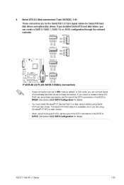
...drives. If you can create a RAID 0, RAID 1, RAID 10, or JBOD configuration through the onboard controller. ASUS F1A55-M LX Series GND RSATA_TXP1 RSATA_TXN1 GND RSATA_RXN1 RSATA_RXP1 GND GND RSATA_TXP2 RSATA_TXN2 GND RSATA_RXN2 RSATA_RXP2 GND GND RSATA_TXP3 RSATA_TXN3 GND RSATA_RXN3 ...GND RSATA_RXN6 RSATA_RXP6 GND Serial ATA 3.0 Gb/s connectors (7-pin SATA3G_1~6) SATA3G_3 SATA3G_5 GND RSATA_TXP5 RSATA_TXN5 GND RSATA_RXN5 RSATA_RXP5 GND F1A55-M LX PLUS F1A55-M LX PLUS SATA 3.0Gb/s connectors • These connectors are using Windows® XP SP3 or later version. • When ...
...drives. If you can create a RAID 0, RAID 1, RAID 10, or JBOD configuration through the onboard controller. ASUS F1A55-M LX Series GND RSATA_TXP1 RSATA_TXN1 GND RSATA_RXN1 RSATA_RXP1 GND GND RSATA_TXP2 RSATA_TXN2 GND RSATA_RXN2 RSATA_RXP2 GND GND RSATA_TXP3 RSATA_TXN3 GND RSATA_RXN3 ...GND RSATA_RXN6 RSATA_RXP6 GND Serial ATA 3.0 Gb/s connectors (7-pin SATA3G_1~6) SATA3G_3 SATA3G_5 GND RSATA_TXP5 RSATA_TXN5 GND RSATA_RXN5 RSATA_RXP5 GND F1A55-M LX PLUS F1A55-M LX PLUS SATA 3.0Gb/s connectors • These connectors are using Windows® XP SP3 or later version. • When ...
User Manual
Page 36
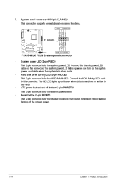
.../soft-off the system power. 1-24 HD_LED+ HD_LEDGround Reset RESET PLED+ PLEDPWR GND Chapter 1: Product introduction PLED PWRBTN System panel connector (10-1 pin F_PANEL) F_PANEL F1A55-M LX PLUS PIN 1 +HDLED F1A55-M LX PLUS System panel connector • System power LED (2-pin PLED) • This 2-pin connector is for the system power button.
.../soft-off the system power. 1-24 HD_LED+ HD_LEDGround Reset RESET PLED+ PLEDPWR GND Chapter 1: Product introduction PLED PWRBTN System panel connector (10-1 pin F_PANEL) F_PANEL F1A55-M LX PLUS PIN 1 +HDLED F1A55-M LX PLUS System panel connector • System power LED (2-pin PLED) • This 2-pin connector is for the system power button.

User Manual
Page 37
... Control Panel > Sounds and Audio Devices > Sound Playback to this connector. Digital audio connector (4-1 pin SPDIF_OUT) F1A55-M LX PLUS SPDIF_OUT F1A55-M LX PLUS Digital audio connector Ensure that the audio device of Sound playback is purchased separately. GND NC SENSE1_RETUR SENSE2_RETUR Front panel ...R PORT2 R SENSE_SEND PORT2 L Legacy AC'97 compliant definition F1A55-M LX PLUS Front panel audio connector • We recommend that supports either High Definition Audio or AC`97 audio standard. ASUS F1A55-M LX Series MIC2 MICPWR Line out_R NC Line out_L NC 1-25 6....
... Control Panel > Sounds and Audio Devices > Sound Playback to this connector. Digital audio connector (4-1 pin SPDIF_OUT) F1A55-M LX PLUS SPDIF_OUT F1A55-M LX PLUS Digital audio connector Ensure that the audio device of Sound playback is purchased separately. GND NC SENSE1_RETUR SENSE2_RETUR Front panel ...R PORT2 R SENSE_SEND PORT2 L Legacy AC'97 compliant definition F1A55-M LX PLUS Front panel audio connector • We recommend that supports either High Definition Audio or AC`97 audio standard. ASUS F1A55-M LX Series MIC2 MICPWR Line out_R NC Line out_L NC 1-25 6....
User Manual
Page 38
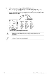
...) USB1112 USB+5V USB_P12USB_P12+ GND NC USB910 USB+5V USB_P10USB_P10+ GND NC USB78 USB+5V USB_P8USB_P8+ GND NC USB+5V USB_P7USB_P7+ GND PIN 1 F1A55-M LX PLUS USB+5V USB_P11USB_P11+ GND F1A55-M LX PLUS USB2.0 connectors Never connect a 1394 cable to 480Mbps connection speed. The USB 2.0 module is purchased separately. 1-26 USB+5V USB_P9USB_P9+ GND PIN 1 PIN...
...) USB1112 USB+5V USB_P12USB_P12+ GND NC USB910 USB+5V USB_P10USB_P10+ GND NC USB78 USB+5V USB_P8USB_P8+ GND NC USB+5V USB_P7USB_P7+ GND PIN 1 F1A55-M LX PLUS USB+5V USB_P11USB_P11+ GND F1A55-M LX PLUS USB2.0 connectors Never connect a 1394 cable to 480Mbps connection speed. The USB 2.0 module is purchased separately. 1-26 USB+5V USB_P9USB_P9+ GND PIN 1 PIN...
User Manual
Page 42
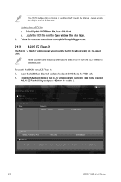
... OS‑based utility. File Info MODEL: F1A55-M LX PLUS Help Info VER: 0202 DATE: 08/03/11 [Enter] Select or Load [Tab] Switch [Up/Down/PageUp/PageDown/Home/End] Move [Esc] Exit [F2] Backup 2-2 ASUS F1A55-M LX Series The ASUS Update utility is capable of the BIOS setup program.... Select Update BIOS from the ASUS website at www.asus.com. Before you to enable it. Exit ASUS EZ Flash 2 Utility V01.02 Flash Info MODEL: F1A55-M LX PLUS File Path: fs0:\ Drive fs0:\ ...
... OS‑based utility. File Info MODEL: F1A55-M LX PLUS Help Info VER: 0202 DATE: 08/03/11 [Enter] Select or Load [Tab] Switch [Up/Down/PageUp/PageDown/Home/End] Move [Esc] Exit [F2] Backup 2-2 ASUS F1A55-M LX Series The ASUS Update utility is capable of the BIOS setup program.... Select Update BIOS from the ASUS website at www.asus.com. Before you to enable it. Exit ASUS EZ Flash 2 Utility V01.02 Flash Info MODEL: F1A55-M LX PLUS File Path: fs0:\ Drive fs0:\ ...
User Manual
Page 43
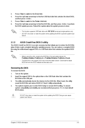
... Folder Info field. • DO NOT shut down or reset the system while updating the BIOS! The utility automatically checks the devices for F1A55-M LX PLUS). Press the Up/Down arrow keys to find the BIOS file, and then press to restore the BIOS file when it fails or gets ... ensure system compatibility and stability, we recommend that allows you to perform the BIOS update process. Download the latest BIOS file from the ASUS website at www.asus.com. Insert the support DVD to recover BIOS setting. Chapter 2: BIOS information 2-3 Reboot the system when the update process is an ...
... Folder Info field. • DO NOT shut down or reset the system while updating the BIOS! The utility automatically checks the devices for F1A55-M LX PLUS). Press the Up/Down arrow keys to find the BIOS file, and then press to restore the BIOS file when it fails or gets ... ensure system compatibility and stability, we recommend that allows you to perform the BIOS update process. Download the latest BIOS file from the ASUS website at www.asus.com. Insert the support DVD to recover BIOS setting. Chapter 2: BIOS information 2-3 Reboot the system when the update process is an ...


