User Manual
Page 1
F1A55-M LX Series • F1A55-M LX • F1A55-M LX PLUS Motherboard
F1A55-M LX Series • F1A55-M LX • F1A55-M LX PLUS Motherboard
User Manual
Page 3
... Notices...vi Safety information...vii About this guide...viii F1A55-M LX Series specifications summary...ix Chapter 1: 1.1 1.2 1.3 Welcome!...1-1 Package contents...1-1 Special features...1-1 1.3.1 1.3.2 Product highlights...1-1 ASUS Exclusive Features...1-2 Product introduction 1.4 1.5 Before you proceed...1-4 Motherboard overview...1-5 1.5.1 1.5.2 1.5.3 1.5.4 1.6.1 1.6.2 1.7.1 1.7.2 1.7.3 1.7.4 1.8.1 1.8.2 1.8.3 1.8.4 1.8.5 Placement direction...1-5 Screw holes...1-5 Motherboard layout...1-6 Layout contents...1-6 Installing the APU...1-7 Installing the heatsink...
... Notices...vi Safety information...vii About this guide...viii F1A55-M LX Series specifications summary...ix Chapter 1: 1.1 1.2 1.3 Welcome!...1-1 Package contents...1-1 Special features...1-1 1.3.1 1.3.2 Product highlights...1-1 ASUS Exclusive Features...1-2 Product introduction 1.4 1.5 Before you proceed...1-4 Motherboard overview...1-5 1.5.1 1.5.2 1.5.3 1.5.4 1.6.1 1.6.2 1.7.1 1.7.2 1.7.3 1.7.4 1.8.1 1.8.2 1.8.3 1.8.4 1.8.5 Placement direction...1-5 Screw holes...1-5 Motherboard layout...1-6 Layout contents...1-6 Installing the APU...1-7 Installing the heatsink...
User Manual
Page 7
...the product, contact a qualified service technician or your retailer. To avoid short circuits, keep paper clips, screws, and staples away from the motherboard, ensure that all the manuals that all power cables from the existing system before using the product, ensure that came with the REACH (Registration... not damaged. If you add a device. DO NOT throw the mercury-containing button cell battery in our products at ASUS REACH website at http://csr.asus.com/english/REACH.htm. If possible, disconnect all cables are correctly connected and the power cables are not sure about the...
...the product, contact a qualified service technician or your retailer. To avoid short circuits, keep paper clips, screws, and staples away from the motherboard, ensure that all the manuals that all power cables from the existing system before using the product, ensure that came with the REACH (Registration... not damaged. If you add a device. DO NOT throw the mercury-containing button cell battery in our products at ASUS REACH website at http://csr.asus.com/english/REACH.htm. If possible, disconnect all cables are correctly connected and the power cables are not sure about the...
User Manual
Page 8
How this guide This user guide contains the information you need when installing and configuring the motherboard. NOTE: Tips and additional information to complete a task. Optional documentation Your product package may include optional documentation, ...change system settings through the BIOS Setup menus. The ASUS website provides updated information on ASUS hardware and software products. Chapter 2: BIOS information This chapter tells how to find more keys simultaneously, the key names are linked with a plus sign (+). IMPORTANT: Instructions that may have been added...
How this guide This user guide contains the information you need when installing and configuring the motherboard. NOTE: Tips and additional information to complete a task. Optional documentation Your product package may include optional documentation, ...change system settings through the BIOS Setup menus. The ASUS website provides updated information on ASUS hardware and software products. Chapter 2: BIOS information This chapter tells how to find more keys simultaneously, the key names are linked with a plus sign (+). IMPORTANT: Instructions that may have been added...
User Manual
Page 13
... ASUS quality motherboards! ASUS F1A55-M LX Series 1-1 The motherboard delivers a host of new features and latest technologies, making it , check the items in the long line of the items is damaged or missing, contact your motherboard package for buying an ASUS® F1A55-M LX Series motherboard! Before you for the following items. Motherboard Cables Accessories Application DVD Documentations • F1A55-M LX Series motherboards include F1A55-M LX PLUS and F1A55-M LX...
... ASUS quality motherboards! ASUS F1A55-M LX Series 1-1 The motherboard delivers a host of new features and latest technologies, making it , check the items in the long line of the items is damaged or missing, contact your motherboard package for buying an ASUS® F1A55-M LX Series motherboard! Before you for the following items. Motherboard Cables Accessories Application DVD Documentations • F1A55-M LX Series motherboards include F1A55-M LX PLUS and F1A55-M LX...
User Manual
Page 14
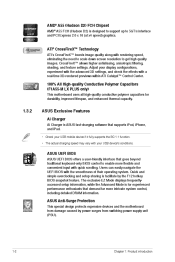
...with a real-time 3D-rendered previews within ATI Catalyst™ Control Center. 100% All High-quality Conductive Polymer Capacitors (F1A55-M LX PLUS only) This motherboard uses all high-quality conductive polymer capacitors for experienced performance enthusiasts that supports iPod, iPhone, and iPad. • Check... information, while the Advanced Mode is for durability, improved lifespan, and enhanced thermal capacity. 1.3.2 ASUS Exclusive Features Ai Charger Ai Charger is ASUS fast-charging software that demand far more flexible and convenient input with your USB mobile device if ...
...with a real-time 3D-rendered previews within ATI Catalyst™ Control Center. 100% All High-quality Conductive Polymer Capacitors (F1A55-M LX PLUS only) This motherboard uses all high-quality conductive polymer capacitors for experienced performance enthusiasts that supports iPod, iPhone, and iPad. • Check... information, while the Advanced Mode is for durability, improved lifespan, and enhanced thermal capacity. 1.3.2 ASUS Exclusive Features Ai Charger Ai Charger is ASUS fast-charging software that demand far more flexible and convenient input with your USB mobile device if ...

User Manual
Page 15
... product and thus mitigate environmental impacts. eliminates the need to switch back and forth between different utilities. ErP ready The motherboard is an auto-recovery tool that allows you to restore a corrupted BIOS file using a bootable floppy disk or an ... the exclusive ASUS features into 256-color boot logos to their default settings. ASUS CrashFree BIOS 3 ASUS CrashFree BIOS 3 is European Union´s Energy-related Products (ErP) ready, and ErP requires products to meet certain energy efficiency requirements in regards to overclocking failure. ASUS F1A55-M LX Series 1-3
... product and thus mitigate environmental impacts. eliminates the need to switch back and forth between different utilities. ErP ready The motherboard is an auto-recovery tool that allows you to restore a corrupted BIOS file using a bootable floppy disk or an ... the exclusive ASUS features into 256-color boot logos to their default settings. ASUS CrashFree BIOS 3 ASUS CrashFree BIOS 3 is European Union´s Energy-related Products (ErP) ready, and ErP requires products to meet certain energy efficiency requirements in regards to overclocking failure. ASUS F1A55-M LX Series 1-3
User Manual
Page 16
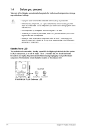
... in soft-off the ATX power supply and detach its power cord. Standby Power LED The motherboard comes with the component. • Before you install or remove any motherboard component. SB_PWR F1A55-M LX PLUS ON Standby Power OFF Powered Off F1A55-M LX PLUS Onboard LED 1-4 Chapter 1: Product introduction The illustration below shows the location of the following precautions...
... in soft-off the ATX power supply and detach its power cord. Standby Power LED The motherboard comes with the component. • Before you install or remove any motherboard component. SB_PWR F1A55-M LX PLUS ON Standby Power OFF Powered Off F1A55-M LX PLUS Onboard LED 1-4 Chapter 1: Product introduction The illustration below shows the location of the following precautions...
User Manual
Page 17
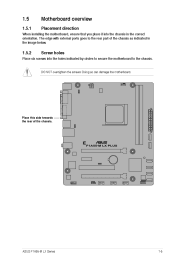
1.5 1.5.1 Motherboard overview Placement direction When installing the motherboard, ensure that you place it into the chassis in the image below. 1.5.2 Place six screws into the holes indicated by circles to secure the motherboard to the rear part of the chassis. DO NOT overtighten the screws! F1A55-M LX PLUS ASUS F1A55-M LX Series 1-5 Doing so can damage the motherboard. Screw holes Place this side towards the rear of the chassis as indicated in the correct orientation. The edge with external ports goes to the chassis.
1.5 1.5.1 Motherboard overview Placement direction When installing the motherboard, ensure that you place it into the chassis in the image below. 1.5.2 Place six screws into the holes indicated by circles to secure the motherboard to the rear part of the chassis. DO NOT overtighten the screws! F1A55-M LX PLUS ASUS F1A55-M LX Series 1-5 Doing so can damage the motherboard. Screw holes Place this side towards the rear of the chassis as indicated in the correct orientation. The edge with external ports goes to the chassis.
User Manual
Page 18
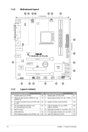
... SATA3G_1~6) 1-21 1-7 1-10 1-23 1-6 Chapter 1: Product introduction 1.5.3 Motherboard layout 1 2 3 4 21.3cm(8.4in) 5 4 6 KB_USB56 ATX12V KBPWR EPU CPU_FAN COM1 DDR3 DIMM_A1 (64bit, 240-pin module) DDR3 DIMM_B1 (64bit, 240-pin module) LPT SOCKET FM1 VGA 3 24.4cm(9.6in) EATXPWR SATA3G_6 LAN1_USB12 USBPW1-6 USB34 CHA_FAN AUDIO F1A55-M LX PLUS PCIEX16_1 RTL 8111E 14 SATA3G_5 7 SB_PWR PCIEX1_1...
... SATA3G_1~6) 1-21 1-7 1-10 1-23 1-6 Chapter 1: Product introduction 1.5.3 Motherboard layout 1 2 3 4 21.3cm(8.4in) 5 4 6 KB_USB56 ATX12V KBPWR EPU CPU_FAN COM1 DDR3 DIMM_A1 (64bit, 240-pin module) DDR3 DIMM_B1 (64bit, 240-pin module) LPT SOCKET FM1 VGA 3 24.4cm(9.6in) EATXPWR SATA3G_6 LAN1_USB12 USBPW1-6 USB34 CHA_FAN AUDIO F1A55-M LX PLUS PCIEX16_1 RTL 8111E 14 SATA3G_5 7 SB_PWR PCIEX1_1...
User Manual
Page 19
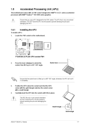
To install a APU: Installing the APU Locate the FM1 socket on the motherboard. Carefully insert the APU into the socket until it up to a 90°-100° angle; DO NOT force the APU ... lift it fits in one correct orientation. The APU fits only in place. 1.6 Accelerated Processing Unit (APU) This motherboard comes with an FM1 socket designed for the FM1 socket. series accelerated processors with a small triangle. F1A55-M LX PLUS F1A55-M LX PLUS CPU socket FM1 2. The APU fits in completely. 3. 4. Small triangle Gold triangle ASUS F1A55-M LX Series 1-7
To install a APU: Installing the APU Locate the FM1 socket on the motherboard. Carefully insert the APU into the socket until it up to a 90°-100° angle; DO NOT force the APU ... lift it fits in one correct orientation. The APU fits only in place. 1.6 Accelerated Processing Unit (APU) This motherboard comes with an FM1 socket designed for the FM1 socket. series accelerated processors with a small triangle. F1A55-M LX PLUS F1A55-M LX PLUS CPU socket FM1 2. The APU fits in completely. 3. 4. Small triangle Gold triangle ASUS F1A55-M LX Series 1-7
User Manual
Page 20
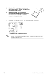
5. 6. When the APU is locked. F1A55-M LX PLUS F1A55-M LX PLUS CPU fan connector DO NOT forget to secure the APU. You can occur if you fail to section 1.6.2 Installing heatsink and fan for instructions. Connect ... place, push down the socket lever to connect the CPU fan connector! The lever clicks on the side tab to the CPU_FAN connector on the motherboard.
5. 6. When the APU is locked. F1A55-M LX PLUS F1A55-M LX PLUS CPU fan connector DO NOT forget to secure the APU. You can occur if you fail to section 1.6.2 Installing heatsink and fan for instructions. Connect ... place, push down the socket lever to connect the CPU fan connector! The lever clicks on the side tab to the CPU_FAN connector on the motherboard.

User Manual
Page 21
...8226; If you purchased a separate CPU heatsink and fan assembly, ensure that a Thermal Interface Material is already installed on the motherboard upon purchase. • You do not match the CPU documentation, follow the latter. 2. CPU Fan CPU Heatsink Retention bracket ...CPU, heatsink, and the retention mechanism. If the instructions in this section do not have to the retention module base. 1 2 3 4 5 ASUS F1A55-M LX Series 1-9 Attach one end of the installed CPU, ensuring that the heatsink fits properly on the retention module base. • The retention module ...
...8226; If you purchased a separate CPU heatsink and fan assembly, ensure that a Thermal Interface Material is already installed on the motherboard upon purchase. • You do not match the CPU documentation, follow the latter. 2. CPU Fan CPU Heatsink Retention bracket ...CPU, heatsink, and the retention mechanism. If the instructions in this section do not have to the retention module base. 1 2 3 4 5 ASUS F1A55-M LX Series 1-9 Attach one end of the installed CPU, ensuring that the heatsink fits properly on the retention module base. • The retention module ...
User Manual
Page 22
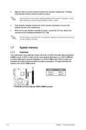
...in place. 4. 5. Align the other end of the DDR3 DIMM sockets: DIMM_A1 DIMM_B1 Channel Channel A Channel B Sockets DIMM_A1 DIMM_B1 F1A55-M LX PLUS F1A55-M LX PLUS 240-pin DDR3 DIMM sockets 1-10 Chapter 1: Product introduction When the fan and heatsink assembly is in place. DDR3 modules are developed... a DDR2 DIMM but is in place, connect the CPU fan cable to plug this connector. 1.7 1.7.1 System memory Overview This motherboard comes with less power consumption. A clicking sound denotes that the fan and heatsink assembly perfectly fits the retention mechanism module base, ...
...in place. 4. 5. Align the other end of the DDR3 DIMM sockets: DIMM_A1 DIMM_B1 Channel Channel A Channel B Sockets DIMM_A1 DIMM_B1 F1A55-M LX PLUS F1A55-M LX PLUS 240-pin DDR3 DIMM sockets 1-10 Chapter 1: Product introduction When the fan and heatsink assembly is in place. DDR3 modules are developed... a DDR2 DIMM but is in place, connect the CPU fan cable to plug this connector. 1.7 1.7.1 System memory Overview This motherboard comes with less power consumption. A clicking sound denotes that the fan and heatsink assembly perfectly fits the retention mechanism module base, ...
User Manual
Page 23
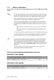
...7V DIMM socket support (Optional) A* B* • • ASUS F1A55-M LX Series 1-11 Under the default state, some memory modules for overclocking may install varying memory sizes in the market. • The default memory operation frequency is dependent on the motherboard. DIMM socket Timing Voltage support (Optional) A* B* 1.65V ... channel is the standard way of the lower-sized channel for the dual-channel configuration. F1A55-M LX Series Motherboard Qualified Vendors Lists (QVL) DDR3-2250(O.C.)MHz capability Vendors KINGSTON Part No. Any excess memory from a memory module.
...7V DIMM socket support (Optional) A* B* • • ASUS F1A55-M LX Series 1-11 Under the default state, some memory modules for overclocking may install varying memory sizes in the market. • The default memory operation frequency is dependent on the motherboard. DIMM socket Timing Voltage support (Optional) A* B* 1.65V ... channel is the standard way of the lower-sized channel for the dual-channel configuration. F1A55-M LX Series Motherboard Qualified Vendors Lists (QVL) DDR3-2250(O.C.)MHz capability Vendors KINGSTON Part No. Any excess memory from a memory module.

User Manual
Page 28
... socket until the retaining clips snap back in only one direction. To remove a DIMM: Removing a DIMM Simultaneously press the retaining clips outward to both the motherboard and the components. 1. 2. The DIMM might get damaged when it fits in place and the DIMM is keyed with your fingers when pressing the retaining...
... socket until the retaining clips snap back in only one direction. To remove a DIMM: Removing a DIMM Simultaneously press the retaining clips outward to both the motherboard and the components. 1. 2. The DIMM might get damaged when it fits in place and the DIMM is keyed with your fingers when pressing the retaining...
User Manual
Page 29
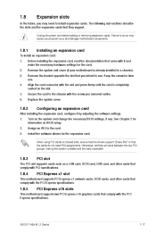
... that came with the PCI Express specifications. Remove the bracket opposite the slot that they support. Turn on BIOS setup. This motherboard supports two PCI Express x16 graphics cards that comply with it by adjusting the software settings. Failure to do not need to ...and change the necessary BIOS settings, if any. PCI slot PCI Express x1 slot PCI Express x16 slots ASUS F1A55-M LX Series 1-17 Align the card connector with the screw you physical injury and damage motherboard components. 1.8.1 1. 2. 3. 4. 5. 6. Secure the card to the chassis with the slot and press...
... that came with the PCI Express specifications. Remove the bracket opposite the slot that they support. Turn on BIOS setup. This motherboard supports two PCI Express x16 graphics cards that comply with it by adjusting the software settings. Failure to do not need to ...and change the necessary BIOS settings, if any. PCI slot PCI Express x1 slot PCI Express x16 slots ASUS F1A55-M LX Series 1-17 Align the card connector with the screw you physical injury and damage motherboard components. 1.8.1 1. 2. 3. 4. 5. 6. Secure the card to the chassis with the slot and press...
User Manual
Page 30
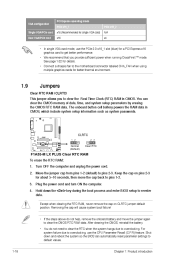
... jumper allows you provide sufficient power when running CrossFireX™ mode. See page 1-22 for details. • Connect a chassis fan to the motherboard connector labeled CHA_FAN when using multiple graphics cards for a PCI Express x16 graphics card to get better performance. • We recommend that you to...) to default values. 1-18 Chapter 1: Product introduction You can automatically reset parameter settings to pins 2-3. Clear RTC RAM (CLRTC) Jumpers CLRTC F1A55-M LX PLUS 1 2 2 3 Normal (Default) Clear RTC F1A55-M LX PLUS Clear RTC RAM To erase the RTC RAM: 1.
... jumper allows you provide sufficient power when running CrossFireX™ mode. See page 1-22 for details. • Connect a chassis fan to the motherboard connector labeled CHA_FAN when using multiple graphics cards for a PCI Express x16 graphics card to get better performance. • We recommend that you to...) to default values. 1-18 Chapter 1: Product introduction You can automatically reset parameter settings to pins 2-3. Clear RTC RAM (CLRTC) Jumpers CLRTC F1A55-M LX PLUS 1 2 2 3 Normal (Default) Clear RTC F1A55-M LX PLUS Clear RTC RAM To erase the RTC RAM: 1.
User Manual
Page 33
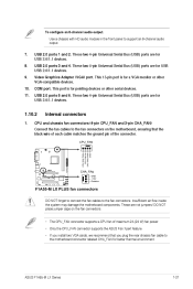
CPU_FAN CPU and chassis fan connectors (4-pin CPU_FAN and 3-pin CHA_FAN) F1A55-M LX PLUS CHA_FAN GND +12V Rotation F1A55-M LX PLUS fan connectors DO NOT forget to connect the fan cables to the fan connectors on the fan connectors. • ...motherboard components. This 15-pin port is for a VGA monitor or other serial devices. 11. 1.10.2 1. This port is for pointing devices or other VGA-compatible devices. Video Graphics Adapter (VGA) port. These two 4-pin Universal Serial Bus (USB) ports are not jumpers! These are for USB 2.0/1.1 devices. 10. ASUS F1A55-M LX...
CPU_FAN CPU and chassis fan connectors (4-pin CPU_FAN and 3-pin CHA_FAN) F1A55-M LX PLUS CHA_FAN GND +12V Rotation F1A55-M LX PLUS fan connectors DO NOT forget to connect the fan cables to the fan connectors on the fan connectors. • ...motherboard components. This 15-pin port is for a VGA monitor or other serial devices. 11. 1.10.2 1. This port is for pointing devices or other VGA-compatible devices. Video Graphics Adapter (VGA) port. These two 4-pin Universal Serial Bus (USB) ports are not jumpers! These are for USB 2.0/1.1 devices. 10. ASUS F1A55-M LX...

User Manual
Page 37
...definition front panel audio module to this connector to avail of the motherboard high-definition audio capability. • If you want to connect a high definition front panel audio module to this connector. ASUS F1A55-M LX Series MIC2 MICPWR Line out_R NC Line out_L NC 1-25 Go ...connector • We recommend that supports either High Definition Audio or AC`97 audio standard. Digital audio connector (4-1 pin SPDIF_OUT) F1A55-M LX PLUS SPDIF_OUT F1A55-M LX PLUS Digital audio connector Ensure that the audio device of the front panel audio I /O module is for details. • The ...
...definition front panel audio module to this connector to avail of the motherboard high-definition audio capability. • If you want to connect a high definition front panel audio module to this connector. ASUS F1A55-M LX Series MIC2 MICPWR Line out_R NC Line out_L NC 1-25 Go ...connector • We recommend that supports either High Definition Audio or AC`97 audio standard. Digital audio connector (4-1 pin SPDIF_OUT) F1A55-M LX PLUS SPDIF_OUT F1A55-M LX PLUS Digital audio connector Ensure that the audio device of the front panel audio I /O module is for details. • The ...


