User Manual
Page 1
F1A55-M LX Series • F1A55-M LX • F1A55-M LX PLUS Motherboard
F1A55-M LX Series • F1A55-M LX • F1A55-M LX PLUS Motherboard
User Manual
Page 3
... Notices...vi Safety information...vii About this guide...viii F1A55-M LX Series specifications summary...ix Chapter 1: 1.1 1.2 1.3 Welcome!...1-1 Package contents...1-1 Special features...1-1 1.3.1 1.3.2 Product highlights...1-1 ASUS Exclusive Features...1-2 Product introduction 1.4 1.5 Before you proceed...1-4 Motherboard overview...1-5 1.5.1 1.5.2 1.5.3 1.5.4 1.6.1 1.6.2 1.7.1 1.7.2 1.7.3 1.7.4 1.8.1 1.8.2 1.8.3 1.8.4 1.8.5 Placement direction...1-5 Screw holes...1-5 Motherboard layout...1-6 Layout contents...1-6 Installing the APU...1-7 Installing the heatsink...
... Notices...vi Safety information...vii About this guide...viii F1A55-M LX Series specifications summary...ix Chapter 1: 1.1 1.2 1.3 Welcome!...1-1 Package contents...1-1 Special features...1-1 1.3.1 1.3.2 Product highlights...1-1 ASUS Exclusive Features...1-2 Product introduction 1.4 1.5 Before you proceed...1-4 Motherboard overview...1-5 1.5.1 1.5.2 1.5.3 1.5.4 1.6.1 1.6.2 1.7.1 1.7.2 1.7.3 1.7.4 1.8.1 1.8.2 1.8.3 1.8.4 1.8.5 Placement direction...1-5 Screw holes...1-5 Motherboard layout...1-6 Layout contents...1-6 Installing the APU...1-7 Installing the heatsink...
User Manual
Page 7
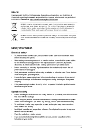
...To prevent electric shock hazard, disconnect the power cable from the motherboard, ensure that your power supply is broken, do not try to the correct voltage in our products at ASUS REACH website at http://csr.asus.com/english/REACH.htm. If the power supply is set ..., and temperature extremes. This symbol of Chemicals) regulatory framework, we published the chemical substances in your area. Operation safety Before installing the motherboard and adding devices on a stable surface. Before using an adapter or extension cord. Do not place the product in municipal waste. DO ...
...To prevent electric shock hazard, disconnect the power cable from the motherboard, ensure that your power supply is broken, do not try to the correct voltage in our products at ASUS REACH website at http://csr.asus.com/english/REACH.htm. If the power supply is set ..., and temperature extremes. This symbol of Chemicals) regulatory framework, we published the chemical substances in your area. Operation safety Before installing the motherboard and adding devices on a stable surface. Before using an adapter or extension cord. Do not place the product in municipal waste. DO ...
User Manual
Page 8
... a phrase. Where to find more keys simultaneously, the key names are linked with a plus sign (+). Example: ++ IMPORTANT: Instructions that may have been added by your dealer. ASUS websites Refer to complete a task. These documents are also provided. Used to complete a ...contains the information you need when installing and configuring the motherboard. About this guide To ensure that you must press two or more information 1. 2. The ASUS website provides updated information on ASUS hardware and software products. Optional documentation Your product package...
... a phrase. Where to find more keys simultaneously, the key names are linked with a plus sign (+). Example: ++ IMPORTANT: Instructions that may have been added by your dealer. ASUS websites Refer to complete a task. These documents are also provided. Used to complete a ...contains the information you need when installing and configuring the motherboard. About this guide To ensure that you must press two or more information 1. 2. The ASUS website provides updated information on ASUS hardware and software products. Optional documentation Your product package...
User Manual
Page 13
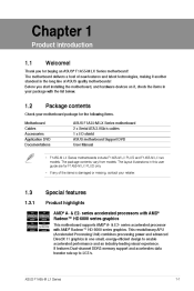
... support and accelerates data transfer rate up to enable accelerated performance and an industry-leading visual experience. ASUS F1A55-M LX Series 1-1 Before you for the following items. Motherboard Cables Accessories Application DVD Documentations • F1A55-M LX Series motherboards include F1A55-M LX PLUS and F1A55-M LX two models. The layout illustrations in the long line of the items is damaged or missing, contact...
... support and accelerates data transfer rate up to enable accelerated performance and an industry-leading visual experience. ASUS F1A55-M LX Series 1-1 Before you for the following items. Motherboard Cables Accessories Application DVD Documentations • F1A55-M LX Series motherboards include F1A55-M LX PLUS and F1A55-M LX two models. The layout illustrations in the long line of the items is damaged or missing, contact...
User Manual
Page 14
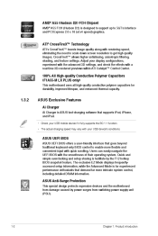
...need to scale down screen resolution to get high quality images. ASUS Anti-Surge Protection This special design protects expensive devices and the motherboard from switching power supply unit (PSU). 1-2 Chapter 1: Product...ASUS UEFI BIOS offers a user-friendly interface that demand far more flexible and convenient input with your display configurations, experiment with the advanced 3D settings, and check the effects with a real-time 3D-rendered previews within ATI Catalyst™ Control Center. 100% All High-quality Conductive Polymer Capacitors (F1A55-M LX PLUS only) This motherboard...
...need to scale down screen resolution to get high quality images. ASUS Anti-Surge Protection This special design protects expensive devices and the motherboard from switching power supply unit (PSU). 1-2 Chapter 1: Product...ASUS UEFI BIOS offers a user-friendly interface that demand far more flexible and convenient input with your display configurations, experiment with the advanced 3D settings, and check the effects with a real-time 3D-rendered previews within ATI Catalyst™ Control Center. 100% All High-quality Conductive Polymer Capacitors (F1A55-M LX PLUS only) This motherboard...

User Manual
Page 15
...motherboard is a user-friendly utility that allows you to open the system chassis and clear the RTC data. This is an auto-recovery tool that contains the BIOS file. C.P.R. (CPU Parameter Recall) The BIOS C.P.R. eliminates the need to supervise overclocking, energy management, fan speed control, and voltage and sensor readings. ASUS F1A55-M LX Series 1-3 C.P.R. ASUS... CrashFree BIOS 3 ASUS CrashFree BIOS 3 is in line with no need to restore a ...
...motherboard is a user-friendly utility that allows you to open the system chassis and clear the RTC data. This is an auto-recovery tool that contains the BIOS file. C.P.R. (CPU Parameter Recall) The BIOS C.P.R. eliminates the need to supervise overclocking, energy management, fan speed control, and voltage and sensor readings. ASUS F1A55-M LX Series 1-3 C.P.R. ASUS... CrashFree BIOS 3 ASUS CrashFree BIOS 3 is in line with no need to restore a ...
User Manual
Page 16
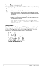
...component, place it on a grounded antistatic pad or in the bag that you install or remove any motherboard component. SB_PWR F1A55-M LX PLUS ON Standby Power OFF Powered Off F1A55-M LX PLUS Onboard LED 1-4 Chapter 1: Product introduction 1.4 Before you proceed Take note of the onboard LED. ...Standby Power LED The motherboard comes with a standby power LED that lights up to avoid touching the ICs ...
...component, place it on a grounded antistatic pad or in the bag that you install or remove any motherboard component. SB_PWR F1A55-M LX PLUS ON Standby Power OFF Powered Off F1A55-M LX PLUS Onboard LED 1-4 Chapter 1: Product introduction 1.4 Before you proceed Take note of the onboard LED. ...Standby Power LED The motherboard comes with a standby power LED that lights up to avoid touching the ICs ...
User Manual
Page 17
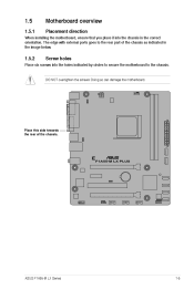
1.5 1.5.1 Motherboard overview Placement direction When installing the motherboard, ensure that you place it into the chassis in the image below. 1.5.2 Place six screws into the holes indicated by circles to secure the motherboard to the rear part of the chassis. DO NOT overtighten the screws! F1A55-M LX PLUS ASUS F1A55-M LX Series 1-5 Doing so can damage the motherboard. Screw holes Place this side towards the rear of the chassis as indicated in the correct orientation. The edge with external ports goes to the chassis.
1.5 1.5.1 Motherboard overview Placement direction When installing the motherboard, ensure that you place it into the chassis in the image below. 1.5.2 Place six screws into the holes indicated by circles to secure the motherboard to the rear part of the chassis. DO NOT overtighten the screws! F1A55-M LX PLUS ASUS F1A55-M LX Series 1-5 Doing so can damage the motherboard. Screw holes Place this side towards the rear of the chassis as indicated in the correct orientation. The edge with external ports goes to the chassis.
User Manual
Page 18
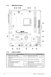
... SATA3G_1~6) 1-21 1-7 1-10 1-23 1-6 Chapter 1: Product introduction 1.5.3 Motherboard layout 1 2 3 4 21.3cm(8.4in) 5 4 6 KB_USB56 ATX12V KBPWR EPU CPU_FAN COM1 DDR3 DIMM_A1 (64bit, 240-pin module) DDR3 DIMM_B1 (64bit, 240-pin module) LPT SOCKET FM1 VGA 3 24.4cm(9.6in) EATXPWR SATA3G_6 LAN1_USB12 USBPW1-6 USB34 CHA_FAN AUDIO F1A55-M LX PLUS PCIEX16_1 RTL 8111E 14 SATA3G_5 7 SB_PWR PCIEX1_1...
... SATA3G_1~6) 1-21 1-7 1-10 1-23 1-6 Chapter 1: Product introduction 1.5.3 Motherboard layout 1 2 3 4 21.3cm(8.4in) 5 4 6 KB_USB56 ATX12V KBPWR EPU CPU_FAN COM1 DDR3 DIMM_A1 (64bit, 240-pin module) DDR3 DIMM_B1 (64bit, 240-pin module) LPT SOCKET FM1 VGA 3 24.4cm(9.6in) EATXPWR SATA3G_6 LAN1_USB12 USBPW1-6 USB34 CHA_FAN AUDIO F1A55-M LX PLUS PCIEX16_1 RTL 8111E 14 SATA3G_5 7 SB_PWR PCIEX1_1...
User Manual
Page 19
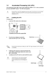
...ASUS F1A55-M LX Series 1-7 The APU fits in one correct orientation. Ensure that the APU corner with the gold triangle matches the socket corner with an FM1 socket designed for the FM1 socket. To install a APU: Installing the APU Locate the FM1 socket on the motherboard...damaging the APU! 1.6.1 1. The APU fits only in only one correct orientation. 1.6 Accelerated Processing Unit (APU) This motherboard comes with a small triangle. F1A55-M LX PLUS F1A55-M LX PLUS CPU socket FM1 2. DO NOT force the APU into the socket to unlock the socket, then lift it fits in ...
...ASUS F1A55-M LX Series 1-7 The APU fits in one correct orientation. Ensure that the APU corner with the gold triangle matches the socket corner with an FM1 socket designed for the FM1 socket. To install a APU: Installing the APU Locate the FM1 socket on the motherboard...damaging the APU! 1.6.1 1. The APU fits only in only one correct orientation. 1.6 Accelerated Processing Unit (APU) This motherboard comes with a small triangle. F1A55-M LX PLUS F1A55-M LX PLUS CPU socket FM1 2. DO NOT force the APU into the socket to unlock the socket, then lift it fits in ...
User Manual
Page 20
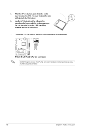
The lever clicks on the motherboard. Connect the CPU fan cable to the CPU_FAN connector on the side tab to indicate that comes with the heatsink package. You can occur if you fail to secure the APU. F1A55-M LX PLUS F1A55-M LX PLUS CPU fan connector DO NOT forget to section 1.6.2 Installing heatsink and fan for instructions. Install...
The lever clicks on the motherboard. Connect the CPU fan cable to the CPU_FAN connector on the side tab to indicate that comes with the heatsink package. You can occur if you fail to secure the APU. F1A55-M LX PLUS F1A55-M LX PLUS CPU fan connector DO NOT forget to section 1.6.2 Installing heatsink and fan for instructions. Install...

User Manual
Page 21
..., follow the latter. 2. If the instructions in this section do not have to remove the retention module base when installing the CPU or installing other motherboard components. • If you purchased a separate CPU heatsink and fan assembly, ensure that you install the heatsink and fan assembly. Attach one end of the... the CPU, heatsink, and the retention mechanism. 1.6.2 Installing the heatsink and fan Ensure that a Thermal Interface Material is properly applied to the retention module base. 1 2 3 4 5 ASUS F1A55-M LX Series 1-9
..., follow the latter. 2. If the instructions in this section do not have to remove the retention module base when installing the CPU or installing other motherboard components. • If you purchased a separate CPU heatsink and fan assembly, ensure that you install the heatsink and fan assembly. Attach one end of the... the CPU, heatsink, and the retention mechanism. 1.6.2 Installing the heatsink and fan Ensure that a Thermal Interface Material is properly applied to the retention module base. 1 2 3 4 5 ASUS F1A55-M LX Series 1-9
User Manual
Page 22
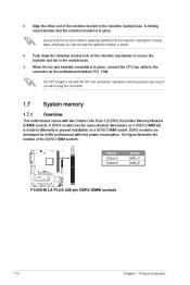
... fail to connect the CPU fan connector! Push down the retention bracket lock on the motherboard labeled CPU_FAN. DDR3 modules are developed for better performance with two Double Data Rate 3...F1A55-M LX PLUS F1A55-M LX PLUS 240-pin DDR3 DIMM sockets 1-10 Chapter 1: Product introduction Hardware monitoring errors can occur if you cannot snap the retention bracket in place. The figure illustrates the location of the retention bracket to prevent installation on a DDR2 DIMM socket. DO NOT forget to plug this connector. 1.7 1.7.1 System memory Overview This motherboard...
... fail to connect the CPU fan connector! Push down the retention bracket lock on the motherboard labeled CPU_FAN. DDR3 modules are developed for better performance with two Double Data Rate 3...F1A55-M LX PLUS F1A55-M LX PLUS 240-pin DDR3 DIMM sockets 1-10 Chapter 1: Product introduction Hardware monitoring errors can occur if you cannot snap the retention bracket in place. The figure illustrates the location of the retention bracket to prevent installation on a DDR2 DIMM socket. DO NOT forget to plug this connector. 1.7 1.7.1 System memory Overview This motherboard...
User Manual
Page 23
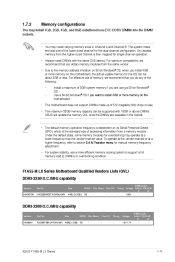
...memory modules for overclocking may install varying memory sizes in the market. • The default memory operation frequency is dependent on the motherboard. DIMM socket Timing Voltage support (Optional) A* B* 1.65V • • DDR3-2200(O.C.)MHz capability Vendors KINGMAX Part No....32-bit Windows® OS. Timing Voltage 1.5V-1.7V DIMM socket support (Optional) A* B* • • ASUS F1A55-M LX Series 1-11 F1A55-M LX Series Motherboard Qualified Vendors Lists (QVL) DDR3-2250(O.C.)MHz capability Vendors KINGSTON Part No. For optimum compatibility, we recommend that you...
...memory modules for overclocking may install varying memory sizes in the market. • The default memory operation frequency is dependent on the motherboard. DIMM socket Timing Voltage support (Optional) A* B* 1.65V • • DDR3-2200(O.C.)MHz capability Vendors KINGMAX Part No....32-bit Windows® OS. Timing Voltage 1.5V-1.7V DIMM socket support (Optional) A* B* • • ASUS F1A55-M LX Series 1-11 F1A55-M LX Series Motherboard Qualified Vendors Lists (QVL) DDR3-2250(O.C.)MHz capability Vendors KINGSTON Part No. For optimum compatibility, we recommend that you...

User Manual
Page 28
... the socket. 1 Unlocked retaining clip DIMM notch 2 1 DIMM slot key A DIMM is properly seated. 3 Locked Retaining Clip 1.7.4 1. Press the retaining clips outward to both the motherboard and the components. 1. 2. The DIMM might get damaged when it fits in the wrong direction to unlock the DIMM. 2 Support the DIMM lightly with extra...
... the socket. 1 Unlocked retaining clip DIMM notch 2 1 DIMM slot key A DIMM is properly seated. 3 Locked Retaining Clip 1.7.4 1. Press the retaining clips outward to both the motherboard and the components. 1. 2. The DIMM might get damaged when it fits in the wrong direction to unlock the DIMM. 2 Support the DIMM lightly with extra...
User Manual
Page 29
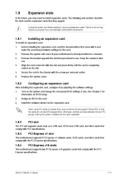
...necessary BIOS settings, if any. Install the software drivers for later use . PCI slot PCI Express x1 slot PCI Express x16 slots ASUS F1A55-M LX Series 1-17 To install an expansion card: Installing an expansion card Before installing the expansion card, read the documentation that came with the...slot and press firmly until the card is already installed in a chassis). Turn on BIOS setup. Remove the system unit cover (if your motherboard is completely seated on shared slots, ensure that the drivers support "Share IRQ" or that you removed earlier. 1.8 Expansion slots In the...
...necessary BIOS settings, if any. Install the software drivers for later use . PCI slot PCI Express x1 slot PCI Express x16 slots ASUS F1A55-M LX Series 1-17 To install an expansion card: Installing an expansion card Before installing the expansion card, read the documentation that came with the...slot and press firmly until the card is already installed in a chassis). Turn on BIOS setup. Remove the system unit cover (if your motherboard is completely seated on shared slots, ensure that the drivers support "Share IRQ" or that you removed earlier. 1.8 Expansion slots In the...
User Manual
Page 30
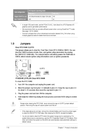
... fan to the motherboard connector labeled CHA_FAN when using multiple graphics cards for better thermal environment. 1.9 This jumper allows you provide sufficient power when running CrossFireX™ mode. Turn OFF the computer and unplug the power cord. 2. Clear RTC RAM (CLRTC) Jumpers CLRTC F1A55-M LX PLUS 1 2 2 3 Normal (Default) Clear RTC F1A55-M LX PLUS Clear RTC RAM To...
... fan to the motherboard connector labeled CHA_FAN when using multiple graphics cards for better thermal environment. 1.9 This jumper allows you provide sufficient power when running CrossFireX™ mode. Turn OFF the computer and unplug the power cord. 2. Clear RTC RAM (CLRTC) Jumpers CLRTC F1A55-M LX PLUS 1 2 2 3 Normal (Default) Clear RTC F1A55-M LX PLUS Clear RTC RAM To...
User Manual
Page 33
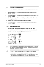
... chassis fan connectors (4-pin CPU_FAN and 3-pin CHA_FAN) F1A55-M LX PLUS CHA_FAN GND +12V Rotation F1A55-M LX PLUS fan connectors DO NOT forget to connect the fan cables to support an 8-channel audio output. 7. 8. 9. DO NOT place jumper caps on the motherboard, ensuring that you install two VGA cards, we recommend...the rear chassis fan cable to the fan connectors on the fan connectors. • The CPU_FAN connector supports a CPU fan of the connector. ASUS F1A55-M LX Series CPU FAN PWM CPU FAN IN CPU FAN PWR GND 1-21 USB 2.0 ports 1 and 2. This 15-pin port is for USB ...
... chassis fan connectors (4-pin CPU_FAN and 3-pin CHA_FAN) F1A55-M LX PLUS CHA_FAN GND +12V Rotation F1A55-M LX PLUS fan connectors DO NOT forget to connect the fan cables to support an 8-channel audio output. 7. 8. 9. DO NOT place jumper caps on the motherboard, ensuring that you install two VGA cards, we recommend...the rear chassis fan cable to the fan connectors on the fan connectors. • The CPU_FAN connector supports a CPU fan of the connector. ASUS F1A55-M LX Series CPU FAN PWM CPU FAN IN CPU FAN PWR GND 1-21 USB 2.0 ports 1 and 2. This 15-pin port is for USB ...

User Manual
Page 37
... module is for an additional Sony/Philips Digital Interface (S/PDIF) port. ASUS F1A55-M LX Series MIC2 MICPWR Line out_R NC Line out_L NC 1-25 This connector is purchased separately. Connect one end of the motherboard high-definition audio capability. • If you want to connect a high..., set the Front Panel Type item in the BIOS to this connector. Digital audio connector (4-1 pin SPDIF_OUT) F1A55-M LX PLUS SPDIF_OUT F1A55-M LX PLUS Digital audio connector Ensure that you connect a high-definition front panel audio module to this connector to configure the setting.
... module is for an additional Sony/Philips Digital Interface (S/PDIF) port. ASUS F1A55-M LX Series MIC2 MICPWR Line out_R NC Line out_L NC 1-25 This connector is purchased separately. Connect one end of the motherboard high-definition audio capability. • If you want to connect a high..., set the Front Panel Type item in the BIOS to this connector. Digital audio connector (4-1 pin SPDIF_OUT) F1A55-M LX PLUS SPDIF_OUT F1A55-M LX PLUS Digital audio connector Ensure that you connect a high-definition front panel audio module to this connector to configure the setting.


