

User Guide
Page 4
... Rail Kit 3-2 3.1.1 Attaching the rack rails 3-2 3.1.2 Mounting the server to the rack 3-4 Chapter 4: Motherboard Info 4.1 Z10PG-D24 Motherboard layout 4-2 4.2 Jumpers...4-4 4.3 Internal connectors 4-8 4.4 Onboard LEDs 4-18 Q-Code table 4-20 Chapter 5: BIOS setup 5.1 Managing and updating your BIOS 5-2 5.1.1 ASUS CrashFree BIOS 3 utility 5-2 5.1.2 ASUS EZ Flash Utility 5-3 5.1.3 BUPDATER utility 5-4 5.2 BIOS setup program 5-6 5.2.1 BIOS menu screen 5-7 5.2.2 Menu bar...
... Rail Kit 3-2 3.1.1 Attaching the rack rails 3-2 3.1.2 Mounting the server to the rack 3-4 Chapter 4: Motherboard Info 4.1 Z10PG-D24 Motherboard layout 4-2 4.2 Jumpers...4-4 4.3 Internal connectors 4-8 4.4 Onboard LEDs 4-18 Q-Code table 4-20 Chapter 5: BIOS setup 5.1 Managing and updating your BIOS 5-2 5.1.1 ASUS CrashFree BIOS 3 utility 5-2 5.1.2 ASUS EZ Flash Utility 5-3 5.1.3 BUPDATER utility 5-4 5.2 BIOS setup program 5-6 5.2.1 BIOS menu screen 5-7 5.2.2 Menu bar...

User Guide
Page 9
...commitment to the highest standards for disposal of electronic products. DO NOT throw the motherboard in providing solutions for detailed recycling information in our products at ASUS REACH website at http://csr.asus.com/english/REACH.htm. Check local regulations for protecting our environment. ix This ... our products, batteries, other components as well as the packaging materials. We believe in municipal waste. Please go to http://csr.asus.com/english/Takeback.htm for you to be able to enable proper reuse of parts and recycling. REACH Information Complying with the REACH...
...commitment to the highest standards for disposal of electronic products. DO NOT throw the motherboard in providing solutions for detailed recycling information in our products at ASUS REACH website at http://csr.asus.com/english/REACH.htm. Check local regulations for protecting our environment. ix This ... our products, batteries, other components as well as the packaging materials. We believe in municipal waste. Please go to http://csr.asus.com/english/Takeback.htm for you to be able to enable proper reuse of parts and recycling. REACH Information Complying with the REACH...
User Guide
Page 11
... you have to install optional components into the barebone server. 4. This chapter includes the motherboard layout, jumper settings, and connector locations. 5. Contents This guide contains the following parts: 1. Chapter 1: Product Introduction This chapter describes the general features of the BIOS ...
... you have to install optional components into the barebone server. 4. This chapter includes the motherboard layout, jumper settings, and connector locations. 5. Contents This guide contains the following parts: 1. Chapter 1: Product Introduction This chapter describes the general features of the BIOS ...
User Guide
Page 14
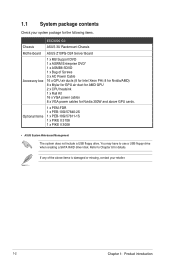
...Items 1 x PEM-FDR 1 x PEB-10G/57840-2S 1 x PEB-10G/57811-1S 1 x PIKE II 3108 1 x PIKE II 3008 • ASUS System Web-based Management The system does not include a USB floppy drive. Refer to use a USB floppy drive when creating a SATA RAID driver disk. 1.1...details. You may have to Chapter 6 for Nvidia 300W and above items is damaged or missing, contact your system package for the following items. ESC8000 G3 Chassis ASUS 3U Rackmount Chassis Motherboard ASUS Z10PG-D24 Server Board Accessory box 1 x MB Support DVD 1 x ASWM Enterprise DVD* 1 x ASMB8 SDVD 1 x Bag of the above ...
...Items 1 x PEM-FDR 1 x PEB-10G/57840-2S 1 x PEB-10G/57811-1S 1 x PIKE II 3108 1 x PIKE II 3008 • ASUS System Web-based Management The system does not include a USB floppy drive. Refer to use a USB floppy drive when creating a SATA RAID driver disk. 1.1...details. You may have to Chapter 6 for Nvidia 300W and above items is damaged or missing, contact your system package for the following items. ESC8000 G3 Chassis ASUS 3U Rackmount Chassis Motherboard ASUS Z10PG-D24 Server Board Accessory box 1 x MB Support DVD 1 x ASWM Enterprise DVD* 1 x ASMB8 SDVD 1 x Bag of the above ...

User Guide
Page 27
... this user guide. 2.3.1 Installing the CPU To install a CPU: 1. For more information, refer to the PnP cap/socket contacts/motherboard components. ASUS ESC8000 G3 2-5 ASUS will process Return Merchandise Authorization (RMA) requests only if the motherboard comes with two surface mount LGA 2011-3 Socket R3 designed for the Intel® Xeon® E5-2600 V3 series...
... this user guide. 2.3.1 Installing the CPU To install a CPU: 1. For more information, refer to the PnP cap/socket contacts/motherboard components. ASUS ESC8000 G3 2-5 ASUS will process Return Merchandise Authorization (RMA) requests only if the motherboard comes with two surface mount LGA 2011-3 Socket R3 designed for the Intel® Xeon® E5-2600 V3 series...

User Guide
Page 29
Align the system such that the socket box is facing toward you and the triangle mark is on your top-right position. triangle mark ASUS ESC8000 G3 2-7 Lift and remove the the CPU heatsink then set aside. 5. 4. Locate the CPU socket box in the motherboard.
Align the system such that the socket box is facing toward you and the triangle mark is on your top-right position. triangle mark ASUS ESC8000 G3 2-7 Lift and remove the the CPU heatsink then set aside. 5. 4. Locate the CPU socket box in the motherboard.

User Guide
Page 32
... securely under the lever (J) then insert the right load lever under the retention tab (K). Do not force to let it may damage the CPU. 14. ASUS will process Return Merchandise Authorization (RMA) requests only if the motherboard comes with the PnP cap on top of the CPU.
... securely under the lever (J) then insert the right load lever under the retention tab (K). Do not force to let it may damage the CPU. 14. ASUS will process Return Merchandise Authorization (RMA) requests only if the motherboard comes with the PnP cap on top of the CPU.

User Guide
Page 36
The figure illustrates the location of the DDR4 DIMM sockets: 2-14 Chapter 2: Hardware setup 2.4 System memory 2.4.1 Overview The motherboard comes with 24 Double Data Rate 4 (DDR4) Dual Inline Memory Modules (DIMM) sockets.
The figure illustrates the location of the DDR4 DIMM sockets: 2-14 Chapter 2: Hardware setup 2.4 System memory 2.4.1 Overview The motherboard comes with 24 Double Data Rate 4 (DDR4) Dual Inline Memory Modules (DIMM) sockets.

User Guide
Page 39
...damaging the DIMM. 3. Hold the DIMM on both ends of the DIMM simultaneously until the retaining clip snaps back into a socket in the motherboard package. • Refer to ensure proper sitting of the memory modules. Apply force to both ends, then insert the DIMM vertically into the... unlock a DIMM socket. The DIMM might get damaged when it fits in any further to the user guide for qualified vendor lists of the DIMM. ASUS ESC8000 G3 2-17 Align a DIMM on the socket. Removing a DIMM from the socket. DIMM notch 2. Support the DIMM lightly with extra force. DO NOT...
...damaging the DIMM. 3. Hold the DIMM on both ends of the DIMM simultaneously until the retaining clip snaps back into a socket in the motherboard package. • Refer to ensure proper sitting of the memory modules. Apply force to both ends, then insert the DIMM vertically into the... unlock a DIMM socket. The DIMM might get damaged when it fits in any further to the user guide for qualified vendor lists of the DIMM. ASUS ESC8000 G3 2-17 Align a DIMM on the socket. Removing a DIMM from the socket. DIMM notch 2. Support the DIMM lightly with extra force. DO NOT...

User Guide
Page 40
... tray from the bay (B). The drive tray support beam provides horizontal support to the motherboard SATA/SAS ports via the SATA/SAS backplane. 2.5.1 Installing 2.5-inch SATA HDD/SAS HDD To install a 2.5-inch HDD: 1. RESET 1 2 3. 2.5 Hard disk drives The ESC8000 G3 system supports hot-swap 2.5-inch SATA/SAS hard disk drives. Place the drive...
... tray from the bay (B). The drive tray support beam provides horizontal support to the motherboard SATA/SAS ports via the SATA/SAS backplane. 2.5.1 Installing 2.5-inch SATA HDD/SAS HDD To install a 2.5-inch HDD: 1. RESET 1 2 3. 2.5 Hard disk drives The ESC8000 G3 system supports hot-swap 2.5-inch SATA/SAS hard disk drives. Place the drive...

User Guide
Page 43
... front I/O board) 5. VGA_HDR1 connector (from motherboard to front I /O board) 7. Serial port (COM port) ASUS ESC8000 G3 2-21 Auxiliary Panel connector (from motherboard to front I /O board) 10. ISATA / ISSATA connectors 4. Panel connector (from motherboard to front I /O connector (from the motherboard to LAN 1 and 2 port on the connectors. 2.6 Cable connections • The bundled system cables are pre-connected before...
... front I/O board) 5. VGA_HDR1 connector (from motherboard to front I /O board) 7. Serial port (COM port) ASUS ESC8000 G3 2-21 Auxiliary Panel connector (from motherboard to front I /O board) 10. ISATA / ISSATA connectors 4. Panel connector (from motherboard to front I /O connector (from the motherboard to LAN 1 and 2 port on the connectors. 2.6 Cable connections • The bundled system cables are pre-connected before...

User Guide
Page 45
...; The stand screw is pre-installed on the motherboard. 2. NGFF3 supports 2260 (22 x 60) M.2 cards while NGFF2 supports 2242 (22 x 42) M.2 cards. Secure the M.2 card with the screw you removed in step 2. stand screw 3. Align and insert the M.2 card into the M.2 connector (NGFF1). ASUS ESC8000 G3 2-23 Locate the M.2 connector (NGFF1) on the screw...
...; The stand screw is pre-installed on the motherboard. 2. NGFF3 supports 2260 (22 x 60) M.2 cards while NGFF2 supports 2242 (22 x 42) M.2 cards. Secure the M.2 card with the screw you removed in step 2. stand screw 3. Align and insert the M.2 card into the M.2 connector (NGFF1). ASUS ESC8000 G3 2-23 Locate the M.2 connector (NGFF1) on the screw...

User Guide
Page 61
This chapter includes the motherboard layout, jumper settings, and connector locations. 4 Chapter 4: Motherboard Info Motherboard Info This chapter gives information about the motherboard that comes with the server.
This chapter includes the motherboard layout, jumper settings, and connector locations. 4 Chapter 4: Motherboard Info Motherboard Info This chapter gives information about the motherboard that comes with the server.

User Guide
Page 62
4.1 Z10PG-D24 Motherboard layout 4-2 Chapter 4: Motherboard information
4.1 Z10PG-D24 Motherboard layout 4-2 Chapter 4: Motherboard information

User Guide
Page 64
... the jumper cap from pins 1-2 (default) to reenter data. Keep the cap on CLRTC jumper default position. After the CMOS clearance, reinstall the battery. 4-4 Chapter 4: Motherboard information Turn OFF the computer and unplug the power cord. 2. Plug the power cord and turn ON the computer. 4. If the steps above do not...
... the jumper cap from pins 1-2 (default) to reenter data. Keep the cap on CLRTC jumper default position. After the CMOS clearance, reinstall the battery. 4-4 Chapter 4: Motherboard information Turn OFF the computer and unplug the power cord. 2. Plug the power cord and turn ON the computer. 4. If the steps above do not...

User Guide
Page 66
4. ME firmware force recovery setting (3-pin ME_RCVR1) This jumper allows you to force Intel Management Engine (ME) boot from recovery mode when ME become corrupted. 5. DDR4 thermal event setting (3-pin DIMMTRIP1) This jumper allows you to enable/disable DDR4 DIMM thermal sensing event pin. 4-6 Chapter 4: Motherboard information
4. ME firmware force recovery setting (3-pin ME_RCVR1) This jumper allows you to force Intel Management Engine (ME) boot from recovery mode when ME become corrupted. 5. DDR4 thermal event setting (3-pin DIMMTRIP1) This jumper allows you to enable/disable DDR4 DIMM thermal sensing event pin. 4-6 Chapter 4: Motherboard information

User Guide
Page 68
ISATA and ISSATA connector (ISATA1, ISSATA1) The ISATA connector (AHCI) supports 4 SATA 6Gb/s ports and Intel RAID/LSI MegaRAID. 4.3 Internal connectors 1. Serial ATA 6.0/3.0 Gb/s connectors (7-pin SATA5, SATA6) These connectors connect to Serial ATA 6.0 Gb/s or 3.0 Gb/s hard disk drives via Serial ATA 6.0Gb/s or 3.0 Gb/s signal cables. The ISSATA connector (AHCI) supports 4 SATA 6Gb/s ports and Intel RAID. 4-8 Chapter 4: Motherboard information The actual data transfer rate depends on the speed of Serial ATA hard disks installed. 2.
ISATA and ISSATA connector (ISATA1, ISSATA1) The ISATA connector (AHCI) supports 4 SATA 6Gb/s ports and Intel RAID/LSI MegaRAID. 4.3 Internal connectors 1. Serial ATA 6.0/3.0 Gb/s connectors (7-pin SATA5, SATA6) These connectors connect to Serial ATA 6.0 Gb/s or 3.0 Gb/s hard disk drives via Serial ATA 6.0Gb/s or 3.0 Gb/s signal cables. The ISSATA connector (AHCI) supports 4 SATA 6Gb/s ports and Intel RAID. 4-8 Chapter 4: Motherboard information The actual data transfer rate depends on the speed of Serial ATA hard disks installed. 2.

User Guide
Page 70
... - 3.95 A (47.4 W maximum). All fans feature the ASUS Smart Fan technology. • FRNT_FAN2, FRNT_FAN4, FRNT_FAN6, and FRNT_FAN8 are not jumpers! Insufficient air flow inside the system may damage the motherboard components. • These are backup fans only. • When ...FRNT_FAN3, FRNT_FAN5, and FRNT_FAN7 does not work, the system activates FRNT_FAN2, FRNT_FAN4, and FRNT_FAN6, and FRNT_FAN8. 4-10 Chapter 4: Motherboard information 5. System fan connectors (4-pin CPU_FAN1-4, FRNT_FAN1-8, HDD_FAN1-2) The fan connectors support cooling fans of the connector. • DO...
... - 3.95 A (47.4 W maximum). All fans feature the ASUS Smart Fan technology. • FRNT_FAN2, FRNT_FAN4, FRNT_FAN6, and FRNT_FAN8 are not jumpers! Insufficient air flow inside the system may damage the motherboard components. • These are backup fans only. • When ...FRNT_FAN3, FRNT_FAN5, and FRNT_FAN7 does not work, the system activates FRNT_FAN2, FRNT_FAN4, and FRNT_FAN6, and FRNT_FAN8. 4-10 Chapter 4: Motherboard information 5. System fan connectors (4-pin CPU_FAN1-4, FRNT_FAN1-8, HDD_FAN1-2) The fan connectors support cooling fans of the connector. • DO...

User Guide
Page 72
Power Supply SMBus connector (12-1 pin PSUSMB1) This connector allows you to connect SMBus (System Management Bus) to the power supply unit to read PSU information. TPM connector (20-1 pin TPM1) This connector supports a Trusted Platform Module (TPM) system, which can securely store keys, digital certificates, passwords, and data. A TPM system also helps enhance network security, protects digital identities, and ensures platform integrity. 9. Devices communicate with an SMBus host and/or other SMBus devices using the SMBus interface. 4-12 Chapter 4: Motherboard information 8.
Power Supply SMBus connector (12-1 pin PSUSMB1) This connector allows you to connect SMBus (System Management Bus) to the power supply unit to read PSU information. TPM connector (20-1 pin TPM1) This connector supports a Trusted Platform Module (TPM) system, which can securely store keys, digital certificates, passwords, and data. A TPM system also helps enhance network security, protects digital identities, and ensures platform integrity. 9. Devices communicate with an SMBus host and/or other SMBus devices using the SMBus interface. 4-12 Chapter 4: Motherboard information 8.

User Guide
Page 74
... on the system power, and blinks when the system is for the system power button. SSI power button/soft-off the system power. 4-14 Chapter 4: Motherboard information Pressing the power switch for the system power LED. System power LED (3-pin PLED) This 3-pin connector is for more than four seconds while...
... on the system power, and blinks when the system is for the system power button. SSI power button/soft-off the system power. 4-14 Chapter 4: Motherboard information Pressing the power switch for the system power LED. System power LED (3-pin PLED) This 3-pin connector is for more than four seconds while...

