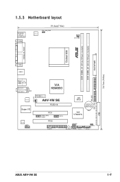
A8V-VM SE User's Manual for English Edtion
Page 14
... another standout in your package with the list below. 1.2 Package contents Check your retailer. 1- Chapter 1: Product introduction 1.1 Welcome! Before you for the following items. Motherboard ASUS A8V-VM SE motherboard Cables Accessories 1 x floppy disk drive cable 1 x Ultra DMA 133/100/66 cable 1 x SATA cable kit (SATA/power) I/O shield Application CD...
A8V-VM SE User's Manual for English Edtion
Page 15
...;S�e�e��p�a�g��e�1��-�8��f�o�r�d��e�t�a�il�s�. ASUS A8V-VM SE 1- These processors provide a dramatic leap forward in compatibility, performance, investment protection, and reduced total cost of the industry's first x86-64 technology. AMD Cool 'n' Quiet...
A8V-VM SE User's Manual for English Edtion
Page 17
... do so may cause severe damage to the motherboard, peripherals, and/or components. Unplug the power cable from the power supply. R A8V-VM SE A8V-VM SE Onboard LED SB_PWR ON Standby Power OFF Powered Off ASUS A8V-VM SE 1- Onboard LED The motherboard comes with the component. • Before you uninstall any component, place it on them due to...
A8V-VM SE User's Manual for English Edtion
Page 19
R DDR DIMM_A1 (64 bit,184-pin module) DDR DIMM_B1 (64 bit,184-pin module) EATXPWR 1.5.3 Motherboard layout PS/2KBM T: Mouse B: Keyboard COM2 19.4cm(7.8in) ATX12V PS2_USB_PWR CPU_FAN Socket 939 PARALLEL PORT VGA USB12 Bottom: USB3 USB4 Top: RJ-45 Top:Line In Center:Line Out Below:Mic In CD RTL8201CL Super I/O ALC660 AAFP CHA_FAN VIA K8M890 PCIEX1_1 A8V-VM SE PCIEX16 4M BIOS CR2032 3V Lithium Cell CMOS Power PCI1 USB56_WFG USB56 PCI2 FLOPPY USB78 VIA VT8237A SPEAKER SB_PWR F_PANEL SATA1 CLRTC SATA2 24.5cm (9.6in) PRI_IDE SEC_IDE ASUS A8V-VM SE 1-
A8V-VM SE User's Manual for English Edtion
Page 21
... the CPU into the socket until it up to a 90°-100° angle. When the CPU is locked. The CPU fits only in completely. 3. ASUS A8V-VM SE 1- Unlock the socket by pressing the lever sideways, then lift it fits in place, push down the socket lever to prevent bending the pins and...
A8V-VM SE User's Manual for English Edtion
Page 23
... retention bracket is in place. Hardware monitoring errors can occur if you cannot snap the retention bracket in place. 4. CPU_FAN R GND +12V Tachometer A8V-VM SE A8V-VM SE CPU Fan Connector ASUS A8V-VM SE Do not forget to plug this connector. 1-11 2. Attach one end of the retention bracket (near the retention bracket lock) to the connector on...
A8V-VM SE User's Manual for English Edtion
Page 25
...-J • • KDL388P4LA-50 • • KDL388P4EA-50 • • VDD9616A8A-5C • • PM4D328D50406EU • • PM4D328S50403DU • • (Continued on the next page) ASUS A8V-VM SE 1-13
A8V-VM SE User's Manual for English Edtion
Page 27
Firmly insert the DIMM into a socket to avoid damaging the DIMM. 3. Simultaneously press the retaining clips outward to both the motherboard and the components. 1. ASUS A8V-VM SE 1-15 Align a DIMM on the socket. 1 2 DDR DIMM notch 1 Unlocked retaining clip A DDR DIMM is properly seated. Locked Retaining Clip 1.7.4 Removing a DIMM Follow these steps ...
A8V-VM SE User's Manual for English Edtion
Page 29
shared - - - - shared - - - - - - Integrated graphics shared - - - - - - - PCI slot 2 - Onboard USB controller 3 - - - shared - - - - shared - - - - - Onboard SATA Controller - ASUS A8V-VM SE 1-17 shared - - - - - - PCI Express x16 slot s� ha� r� ed PCI Express x1 slot 1 s� ha� r� ed Onboard USB controller 0 shared - - - - - - - Onboard ...
A8V-VM SE User's Manual for English Edtion
Page 31
... and enter BIOS setup to pins 2-3. Remove the battery. 3. Keep the cap on CLRTC jumper default position. To erase the RTC RAM: 1. R A8V-VM SE A8V-VM SE Clear RTC RAM CLRTC 12 23 Normal (Default) Clear CMOS Except when clearing the RTC RAM, never remove the cap on pins 2-3 for about 5-10...move the cap back to clear the Real Time Clock (RTC) RAM in the CMOS, which includes the system setup information such as system passwords. ASUS A8V-VM SE 1-19 Re-install the battery. 5. Plug the power cord and turn ON the computer. 6. You can clear the CMOS memory of date, time,...
A8V-VM SE User's Manual for English Edtion
Page 33
... 100 Mbps to the table below for a PS/2 mouse. 2. This port connects a microphone. 1.10 Connectors 1.10.1 Rear panel connectors 1 2 3 4 5 6 11 10 9 8 7 1. LAN (RJ-45) port. ASUS A8V-VM SE 1-21 This port is for the LAN port LED indications. LAN port LED indications 100 Mbps LED 10 Mbps LED 100 Mbps 10 Mbps LED...
A8V-VM SE User's Manual for English Edtion
Page 35
... r Black or gray • Pin 20 on the Ultra DMA cable connector. There are for Ultra DMA 133/100/66 IDE devices. PRI_IDE R SEC_IDE A8V-VM SE A8V-VM SE IDE Connectors ASUS A8V-VM SE 1-23 This prevents incorrect insertion when you connect the IDE cable. • Use the 80-conductor IDE cable for Ultra DMA 133/100/66...
A8V-VM SE User's Manual for English Edtion
Page 37
... fan connectors! Insufficient air flow inside the system may damage the motherboard components. 5. Connect the fan cables to the fan connectors. CPU_FAN R GND +12V Tachometer A8V-VM SE CHA_FAN GND +12V Tachometer A8V-VM SE Fan Connectors ASUS A8V-VM SE 1-25
A8V-VM SE User's Manual for English Edtion
Page 39
... +5 Volts +5 Volts -5 Volts Ground Ground Ground PSON# Ground -12 Volts +3 Volts • We recommend that the PSU has a minimum power rating of 300 W power rating. ASUS A8V-VM SE 1-27 7. otherwise, the system will not boot up if the power is inadequate. • You must install a PSU with a higher power rating if you use...
A8V-VM SE User's Manual for English Edtion
Page 41
.... Refer to the HDD. • Power/Soft-off the system power. R PLED PWRSW PLED+ PLEDPWR GND A8V-VM SE F_PANEL IDELED+ IDELED- Connect the HDD Activity LED cable to this connector. ASUS A8V-VM SE 1-29 Ground Reset HDLED RESET A8V-VM SE System Panel Connector The system panel connector is for easy connection. Connect the chassis power LED cable...
A8V-VM SE User's Manual for English Edtion
Page 45
Copy the original or the latest motherboard BIOS file to the bootable floppy disk. 2.1.2 ASUS EZ Flash utility The ASUS EZ Flash feature allows you rename the BIOS file to A8VVMSE.ROM. EZFlash starting BIOS update Checking for floppy... 4. Flashed successfully. ... using EZ Flash: 1. Insert the floppy disk that you to update the BIOS without having to download the latest BIOS file for floppy... Start programming... ASUS A8V-VM SE 2- d. Press , then follow screen instructions to a floppy disk, then restart the system. 3. Press + during the Power-On Self Tests (POST). ...
A8V-VM SE User's Manual for English Edtion
Page 47
... the BIOS update process is the latest or the original BIOS file on a piece of paper. All rights reserved. done Please restart your computer 100% ASUS A8V-VM SE 2- Copy the AFUDOS utility (afudos.exe) from the hard disk drive. A:\>afudos /iA8VVMSE.ROM AMI Firmware Update Utility - Version 1.19 Copyright (C) 2003 American Megatrends, Inc...
A8V-VM SE User's Manual for English Edtion
Page 49
... drive, then turn on the system. 2. Bad BIOS checksum. Starting BIOS recovery... The utility then updates the corrupted BIOS file. Visit the ASUS website (www.asus.com) to the optical drive. 3. ASUS A8V-VM SE 2- Checking for floppy... Checking for floppy... Insert the support CD to download the latest BIOS file. Starting BIOS recovery... Completed. DO...
A8V-VM SE User's Manual for English Edtion
Page 51
Select the ASUS FTP site nearest you to avoid network traffic, or click Auto Select. ASUS A8V-VM SE 2- Click Next. Updating the BIOS through the Internet To update the BIOS through the Internet: 1. The ASUS Update main window appears. 2. Launch the ASUS Update utility from the drop‑down menu, then click Next. 3. Select Update BIOS from the Internet option from the Windows® desktop by clicking Start > Programs > ASUS > ASUSUpdate > ASUSUpdate.
A8V-VM SE User's Manual for English Edtion
Page 53
... hub. The firmware hub on your system using the BIOS Setup program so that you with its test routines. Do this program. ASUS A8V-VM SE 2-11 otherwise, POST continues with the opportunity to run this last option only if the first two failed. The Setup program is ...reconfiguring your BIOS." For example, you can change the power management settings. If you to reconfigure your screen. • Visit the ASUS website (www.asus.com) to download the latest BIOS file for most conditions to ensure optimum performance. Select the Load Default Settings item under the Exit ...