Hardware Manual
Page 1
...Gaulle Cedex, France Phone 01-48638989 ALPINE ITALIA S.p.A. Portal de Gamarra 36, Pabellón, 32 01013 Vitoria (Alava)-APDO 133, Spain Phone 945-283588 Designed by ALPINE Japan Printed in Japan (Y) 68-02065Z14-A R NVE-N872A Satellite Linked Navigation HARDWARE MANUAL Please read before using ...this product. Phone 0870-33 33 763 ALPINE ELECTRONICS FRANCE S.A.R.L. (RCS PONTOISE B 338 101 280) 98,...
...Gaulle Cedex, France Phone 01-48638989 ALPINE ITALIA S.p.A. Portal de Gamarra 36, Pabellón, 32 01013 Vitoria (Alava)-APDO 133, Spain Phone 945-283588 Designed by ALPINE Japan Printed in Japan (Y) 68-02065Z14-A R NVE-N872A Satellite Linked Navigation HARDWARE MANUAL Please read before using ...this product. Phone 0870-33 33 763 ALPINE ELECTRONICS FRANCE S.A.R.L. (RCS PONTOISE B 338 101 280) 98,...
Hardware Manual
Page 13
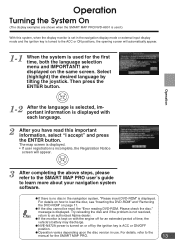
...to the manual for an extended period of time, the vehicle's battery may discharge. a NVE-N872A power is used for the first time, both the language selection menu and IMPORTANT! Operation Turning the System On (The display examples are displayed on or off for the SMART MAP PRO. 13 Select...to an authorized Alpine dealer. message is not resolved, Tips return to load the disc, see "Inserting the DVD-ROM" and "Removing the DVD-ROM" on with each language. 2 After you have read , the "Error reading DVD-ROM. a If there is no disc in the navigation system, "Please ...
...to the manual for an extended period of time, the vehicle's battery may discharge. a NVE-N872A power is used for the first time, both the language selection menu and IMPORTANT! Operation Turning the System On (The display examples are displayed on or off for the SMART MAP PRO. 13 Select...to an authorized Alpine dealer. message is not resolved, Tips return to load the disc, see "Inserting the DVD-ROM" and "Removing the DVD-ROM" on with each language. 2 After you have read , the "Error reading DVD-ROM. a If there is no disc in the navigation system, "Please ...
Installation Guide
Page 1
R Satellite Linked Navigation NVE-N872A Guide for Installation and Connections English Guide d'installation et de connexion Français Guía de instalación y conexiones Español
R Satellite Linked Navigation NVE-N872A Guide for Installation and Connections English Guide d'installation et de connexion Français Guía de instalación y conexiones Español
Installation Guide
Page 8
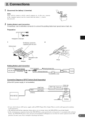
... computer etc. Preparation Navigation side lead 1 Solderless connector 2 (supplied with the unit) Vehicle lead Stopper Navigation side lead Pliers Parking Brake Lead Connection PARKING BRAKE NVE-N872A (Yellow/Blue) Pinch... Connector Parking brake lamp Parking brake lead Parking brake switch Battery Chassis Connection Diagram of the computer memory may be erased when the battery (-) lead is enough to connect the parking brake lead, speed sensor lead, etc. in systems...
... computer etc. Preparation Navigation side lead 1 Solderless connector 2 (supplied with the unit) Vehicle lead Stopper Navigation side lead Pliers Parking Brake Lead Connection PARKING BRAKE NVE-N872A (Yellow/Blue) Pinch... Connector Parking brake lamp Parking brake lead Parking brake switch Battery Chassis Connection Diagram of the computer memory may be erased when the battery (-) lead is enough to connect the parking brake lead, speed sensor lead, etc. in systems...
Installation Guide
Page 10
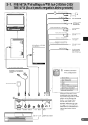
... 13P RGB Extension Cable Included Microphone for voice recognition/ Speak button for future system expansion 9 We strongly recommend that the installation be performed by a trained, authorized Alpine dealer. NVE-N872A Wiring Diagram With IVA-D310/IVA-D300/ TME-M770 (Touch panel-compatible Alpine products) (10A) Battery Lead (Yellow) ACC (Ignition) (Red) BATTERY To the Acc... speed pulse line may result in an accident and loss of chassis body with screw To the Illumination signal line POWER SUPPLY REMOTE IN / OUT NAVIGATION IN DISPLAY OUT SUBW.
... 13P RGB Extension Cable Included Microphone for voice recognition/ Speak button for future system expansion 9 We strongly recommend that the installation be performed by a trained, authorized Alpine dealer. NVE-N872A Wiring Diagram With IVA-D310/IVA-D300/ TME-M770 (Touch panel-compatible Alpine products) (10A) Battery Lead (Yellow) ACC (Ignition) (Red) BATTERY To the Acc... speed pulse line may result in an accident and loss of chassis body with screw To the Illumination signal line POWER SUPPLY REMOTE IN / OUT NAVIGATION IN DISPLAY OUT SUBW.
Installation Guide
Page 12
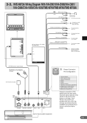
3-3. We strongly recommend that the installation be performed by a trained, authorized Alpine dealer. Use for voice recognition (Included) GPS Antenna (Included) A GPS ANTENNA 5 1 10...-INT function (-) output for Audio Mute 13P RGB Extension Cable Included Microphone for voice recognition/ Speak button for future system expansion 11 PRE IN/OUT REAR FRONT L Ai-NET R 2 1 VIDEO AUX OUT L AUDIO R VIDEO (...the brakes or air bags). Such failures may cause important safety features of life. NVE-N872A Wiring Diagram With IVA-D901/IVA-D900/IVA-C801/ IVA-C800/CVA-1006/CVA...
3-3. We strongly recommend that the installation be performed by a trained, authorized Alpine dealer. Use for voice recognition (Included) GPS Antenna (Included) A GPS ANTENNA 5 1 10...-INT function (-) output for Audio Mute 13P RGB Extension Cable Included Microphone for voice recognition/ Speak button for future system expansion 11 PRE IN/OUT REAR FRONT L Ai-NET R 2 1 VIDEO AUX OUT L AUDIO R VIDEO (...the brakes or air bags). Such failures may cause important safety features of life. NVE-N872A Wiring Diagram With IVA-D901/IVA-D900/IVA-C801/ IVA-C800/CVA-1006/CVA...
Installation Guide
Page 13
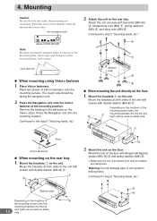
Air ventilation hole (Rear of NVE-N872A) Note: The main unit must be mounted within ±5 degrees of the... be used on either side. Continued to front. 2 Attach the unit on the Velcro strips. Press the Navigation unit onto the mounting location. Mount the unit on the floor. Mounting Caution Do not block the unit's fan... pieces of the mounting screw holes, the 3 1 mounting brackets (for the left and right) can be facing the navigation unit. 2 Press the Navigation unit onto the Velcro fastener at both sides of the unit with screws with double washer (M4×8) 3. 1 ...
Air ventilation hole (Rear of NVE-N872A) Note: The main unit must be mounted within ±5 degrees of the... be used on either side. Continued to front. 2 Attach the unit on the Velcro strips. Press the Navigation unit onto the mounting location. Mount the unit on the floor. Mounting Caution Do not block the unit's fan... pieces of the mounting screw holes, the 3 1 mounting brackets (for the left and right) can be facing the navigation unit. 2 Press the Navigation unit onto the Velcro fastener at both sides of the unit with screws with double washer (M4×8) 3. 1 ...


