Hardware Manual
Page 1
...;n, 32 01013 Vitoria (Alava)-APDO 133, Spain Phone 945-283588 Designed by ALPINE Japan Printed in Japan (Y) 68-02065Z14-A R NVE-N872A Satellite Linked Navigation HARDWARE MANUAL Please read before using this product. Colombo 8, 20090 Trezzano Sul Naviglio (MI), Italy Phone 02-484781 ALPINE ELECTRONICS DE ESPAÑA, S.A. MANUAL DE HARDWARE Lea lo siguiente antes de...
...;n, 32 01013 Vitoria (Alava)-APDO 133, Spain Phone 945-283588 Designed by ALPINE Japan Printed in Japan (Y) 68-02065Z14-A R NVE-N872A Satellite Linked Navigation HARDWARE MANUAL Please read before using this product. Colombo 8, 20090 Trezzano Sul Naviglio (MI), Italy Phone 02-484781 ALPINE ELECTRONICS DE ESPAÑA, S.A. MANUAL DE HARDWARE Lea lo siguiente antes de...
Hardware Manual
Page 9
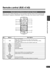
... Selection − − Display Angle DOWN (only pressing MODE button) Display Angle UP (only pressing MODE button) − − Switching AUDIO/NAV. Before Using This System Remote control (RUE-4140) Remote Control Reference Guide for 5 seconds.) 9 Switch, on the side of the remote control, to ! (Flashes the Status Indicator for Head...
... Selection − − Display Angle DOWN (only pressing MODE button) Display Angle UP (only pressing MODE button) − − Switching AUDIO/NAV. Before Using This System Remote control (RUE-4140) Remote Control Reference Guide for 5 seconds.) 9 Switch, on the side of the remote control, to ! (Flashes the Status Indicator for Head...
Hardware Manual
Page 10
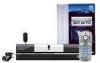
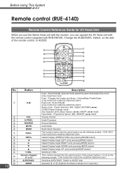
Before Using This System Remote control (RUE-4140) Remote Control Reference Guide for 5 seconds.) Operates 8 to # (Flashes the Status Indicator for AV Head Unit When you use the Alpine head unit with the monitor, you can operate the AV head unit with the remote control (supplied with NVE-N872A). Change the AUDIO/NAV. " # $ % & ( 10 VOL...
Before Using This System Remote control (RUE-4140) Remote Control Reference Guide for 5 seconds.) Operates 8 to # (Flashes the Status Indicator for AV Head Unit When you use the Alpine head unit with the monitor, you can operate the AV head unit with the remote control (supplied with NVE-N872A). Change the AUDIO/NAV. " # $ % & ( 10 VOL...
Hardware Manual
Page 13
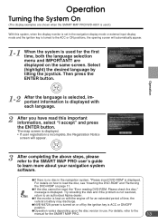
... system, when the display monitor is set in the navigation display mode or external input display mode and the ignition key is turned to the ACC or ON positions, the opening screen will appear. 3 After completing the above steps, please refer to the SMART MAP PRO user's guide to an authorized Alpine dealer. a NVE-N872A...
... system, when the display monitor is set in the navigation display mode or external input display mode and the ignition key is turned to the ACC or ON positions, the opening screen will appear. 3 After completing the above steps, please refer to the SMART MAP PRO user's guide to an authorized Alpine dealer. a NVE-N872A...
Installation Guide
Page 1
R Satellite Linked Navigation NVE-N872A Guide for Installation and Connections English Guide d'installation et de connexion Français Guía de instalación y conexiones Español
R Satellite Linked Navigation NVE-N872A Guide for Installation and Connections English Guide d'installation et de connexion Français Guía de instalación y conexiones Español
Installation Guide
Page 3
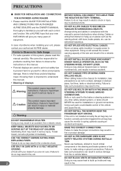
...and may result in serious injury or death. Arrange wiring and cables in compliance with your authorized ALPINE dealer. Knowing them can result in fire, etc. Failure to other safety-related system), or tanks should NEVER be used for installation, take precautions so as the steering wheel, shift... OR ALTER. KEEP SMALL OBJECTS SUCH AS BOLTS OR SCREWS OUT OF THE REACH OF CHILDREN. Cables or wiring that your new NVE-N872A will exceed the current carrying capacity of problems when installing your unit, please contact your dealer if you many years of displays This...
...and may result in serious injury or death. Arrange wiring and cables in compliance with your authorized ALPINE dealer. Knowing them can result in fire, etc. Failure to other safety-related system), or tanks should NEVER be used for installation, take precautions so as the steering wheel, shift... OR ALTER. KEEP SMALL OBJECTS SUCH AS BOLTS OR SCREWS OUT OF THE REACH OF CHILDREN. Cables or wiring that your new NVE-N872A will exceed the current carrying capacity of problems when installing your unit, please contact your dealer if you many years of displays This...
Installation Guide
Page 5
NVE-N872A Wiring Diagram With CVA-1014/CVA-1004/ CVA-1003 10 3-3. Contents PRECAUTIONS 2 1. NVE-N872A Wiring Diagram With IVA-D310/IVA-D300/ TME-M770 (Touch panel-compatible Alpine products) 9 3-2. Connections 7 3-1. NVE-N872A Wiring Diagram With IVA-D901/IVA-D900/ IVA-C801/IVA-C800/CVA-1006/CVA-1005/TME-M790/ TME-M760/TME-M750A 11 4. Mounting 12 5. Confirmation 13 4 Preparation 5 2.
NVE-N872A Wiring Diagram With CVA-1014/CVA-1004/ CVA-1003 10 3-3. Contents PRECAUTIONS 2 1. NVE-N872A Wiring Diagram With IVA-D310/IVA-D300/ TME-M770 (Touch panel-compatible Alpine products) 9 3-2. Connections 7 3-1. NVE-N872A Wiring Diagram With IVA-D901/IVA-D900/ IVA-C801/IVA-C800/CVA-1006/CVA-1005/TME-M790/ TME-M760/TME-M750A 11 4. Mounting 12 5. Confirmation 13 4 Preparation 5 2.
Installation Guide
Page 8
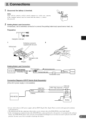
...its switch is placed in the OFF position. Preparation Navigation side lead 1 Solderless connector 2 (supplied with the unit) Vehicle lead Stopper Navigation side lead Pliers Parking Brake Lead Connection PARKING BRAKE NVE-N872A (Yellow/Blue) Pinch Connector Parking brake lamp Parking ... 1 Disconnect the battery (-) terminal. in systems where the NVE-N872A is used individually. • If the switched power (ignition) lead of the NVE-N872A is connected directly to the positive (+) terminal of the vehicle's battery, the NVE-N872A draws some cases, this case, contents of...
...its switch is placed in the OFF position. Preparation Navigation side lead 1 Solderless connector 2 (supplied with the unit) Vehicle lead Stopper Navigation side lead Pliers Parking Brake Lead Connection PARKING BRAKE NVE-N872A (Yellow/Blue) Pinch Connector Parking brake lamp Parking ... 1 Disconnect the battery (-) terminal. in systems where the NVE-N872A is used individually. • If the switched power (ignition) lead of the NVE-N872A is connected directly to the positive (+) terminal of the vehicle's battery, the NVE-N872A draws some cases, this case, contents of...
Installation Guide
Page 10
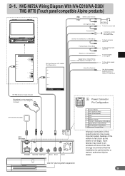
...an accident and loss of life. We strongly recommend that the installation be performed by a trained, authorized Alpine dealer. NVE-N872A Wiring Diagram With IVA-D310/IVA-D300/ TME-M770 (Touch panel-compatible Alpine products) (10A) Battery Lead (Yellow) ACC (Ignition) (Red) BATTERY To the Acc power lead...IN-INT function (-) output for Audio Mute 13P RGB Extension Cable Included Microphone for voice recognition/ Speak button for future system expansion 9 Such failures may cause important safety features of chassis body with screw To the Illumination signal line POWER SUPPLY REMOTE IN ...
...an accident and loss of life. We strongly recommend that the installation be performed by a trained, authorized Alpine dealer. NVE-N872A Wiring Diagram With IVA-D310/IVA-D300/ TME-M770 (Touch panel-compatible Alpine products) (10A) Battery Lead (Yellow) ACC (Ignition) (Red) BATTERY To the Acc power lead...IN-INT function (-) output for Audio Mute 13P RGB Extension Cable Included Microphone for voice recognition/ Speak button for future system expansion 9 Such failures may cause important safety features of chassis body with screw To the Illumination signal line POWER SUPPLY REMOTE IN ...
Installation Guide
Page 11
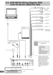
We strongly recommend that the installation be performed by a trained, authorized Alpine dealer. Such failures may cause important safety features of life. NVE-N872A Wiring Diagram With CVA-1014/CVA-1004/CVA-1003 (10A) Battery Lead (Yellow) ACC (Ignition) (Red) Ground (Black) Dimmer In (Illumination) (+) (White/Blue) Parking Brake (... to connect a device having the IN-INT function (-) output for Audio Mute 13P RGB Extension Cable Included Microphone for voice recognition/ Speak button for future system expansion 10 3-2.
We strongly recommend that the installation be performed by a trained, authorized Alpine dealer. Such failures may cause important safety features of life. NVE-N872A Wiring Diagram With CVA-1014/CVA-1004/CVA-1003 (10A) Battery Lead (Yellow) ACC (Ignition) (Red) Ground (Black) Dimmer In (Illumination) (+) (White/Blue) Parking Brake (... to connect a device having the IN-INT function (-) output for Audio Mute 13P RGB Extension Cable Included Microphone for voice recognition/ Speak button for future system expansion 10 3-2.
Installation Guide
Page 12
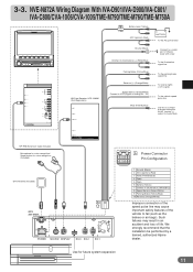
We strongly recommend that the installation be performed by a trained, authorized Alpine dealer. Use for voice recognition (Included) GPS Antenna (Included) A GPS ANTENNA 5 ... RGB Extension Cable Included Microphone for voice recognition/ Speak button for future system expansion 11 NVE-N872A Wiring Diagram With IVA-D901/IVA-D900/IVA-C801/ IVA-C800/CVA-...1006/CVA-1005/TME-M790/TME-M760/TME-M750A (10A) Battery Lead (Yellow) ACC (Ignition) (Red) BATTERY To the Acc power lead POWER SUPPLY REMOTE IN/OUT NAVIGATION...
We strongly recommend that the installation be performed by a trained, authorized Alpine dealer. Use for voice recognition (Included) GPS Antenna (Included) A GPS ANTENNA 5 ... RGB Extension Cable Included Microphone for voice recognition/ Speak button for future system expansion 11 NVE-N872A Wiring Diagram With IVA-D901/IVA-D900/IVA-C801/ IVA-C800/CVA-...1006/CVA-1005/TME-M790/TME-M760/TME-M750A (10A) Battery Lead (Yellow) ACC (Ignition) (Red) BATTERY To the Acc power lead POWER SUPPLY REMOTE IN/OUT NAVIGATION...
Installation Guide
Page 13
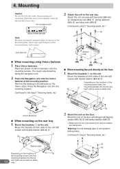
Mounting Caution Do not block the unit's fan, thus preventing air circulation. Air ventilation hole (Rear of NVE-N872A) Note: The main unit must be used on either side. The rough side should be used on either side. 1 Floor Velcro fasteners a When mounting on ... (for the left and right) can be mounted within ±5 degrees of the horizontal plane, left 12 and right) can be facing the navigation unit. 2 Press the Navigation unit onto the Velcro fastener at both sides of Velcro fasteners onto the mounting surface. Continued to right, and 30 degrees of the unit...
Mounting Caution Do not block the unit's fan, thus preventing air circulation. Air ventilation hole (Rear of NVE-N872A) Note: The main unit must be used on either side. The rough side should be used on either side. 1 Floor Velcro fasteners a When mounting on ... (for the left and right) can be mounted within ±5 degrees of the horizontal plane, left 12 and right) can be facing the navigation unit. 2 Press the Navigation unit onto the Velcro fastener at both sides of Velcro fasteners onto the mounting surface. Continued to right, and 30 degrees of the unit...


