Owners Manual
Page 2
... RCA video input terminals 24 Confirmation 25 Calibration Introduction 26 What is Detected 10 Moving object verification icon 10 Camera Image 10 About the rear camera guide 11 Error between "Calibration Mode" and "Normal Use Mode 26 Preparation 26 Accessory parts 26 Necessary tools 26 Necessary space for work 27 Prepare the Car Body 27 Affixing the calibration sheets .......27 About Operation in Calibration Mode 30 Performing Calibration 31 Information Specifications 35...
... RCA video input terminals 24 Confirmation 25 Calibration Introduction 26 What is Detected 10 Moving object verification icon 10 Camera Image 10 About the rear camera guide 11 Error between "Calibration Mode" and "Normal Use Mode 26 Preparation 26 Accessory parts 26 Necessary tools 26 Necessary space for work 27 Prepare the Car Body 27 Affixing the calibration sheets .......27 About Operation in Calibration Mode 30 Performing Calibration 31 Information Specifications 35...
Owners Manual
Page 3
... USE SPECIFIC VEHICLE CALIBRATION KIT OTHERWISE IT WILL NOT ACCURATELY DISPLAY IMAGES. Swallowing them can scan non-moving from looking ahead of the vehicle and cause an accident. The Object detection function assists the driver in an accident. USE THE CORRECT AMPERE RATING WHEN REPLACING FUSES. SERIOUS INJURY OR DEATH CAN RESULT. ~WARNING This symbol means important instructions. WHEN USING A CAMERA SYSTEM, THE DRIVER...
... USE SPECIFIC VEHICLE CALIBRATION KIT OTHERWISE IT WILL NOT ACCURATELY DISPLAY IMAGES. Swallowing them can scan non-moving from looking ahead of the vehicle and cause an accident. The Object detection function assists the driver in an accident. USE THE CORRECT AMPERE RATING WHEN REPLACING FUSES. SERIOUS INJURY OR DEATH CAN RESULT. ~WARNING This symbol means important instructions. WHEN USING A CAMERA SYSTEM, THE DRIVER...
Owners Manual
Page 4
... could cause the strength of the camera mounting to weaken, which may result in fire or damage to the volume of the car radio, etc., it to fall of being hit. USE SPECIFIED ACCESSORY PARTS AND INSTALL THEM SECURELY. Failure to the car body. USE THIS PRODUCT FOR MOBILE 12V APPLICATIONS. BE CAREFUL WHEN SETTING THE ALARM VOLUME. Objects that obstruct or hang up...
... could cause the strength of the camera mounting to weaken, which may result in fire or damage to the volume of the car radio, etc., it to fall of being hit. USE SPECIFIED ACCESSORY PARTS AND INSTALL THEM SECURELY. Failure to the car body. USE THIS PRODUCT FOR MOBILE 12V APPLICATIONS. BE CAREFUL WHEN SETTING THE ALARM VOLUME. Objects that obstruct or hang up...
Owners Manual
Page 5
... of the rear lamp. When connecting the HCE-C305R to the power cable of damage to the unit in damage to other fitting. HALT USE IMMEDIATELY IF A PROBLEM APPEARS. CHECK WIRING WHEN ATTACHING. This can result in shortcircuit, fire or electric shock. • About Calibration Settings Obstacle detection performance adjustment and guidance mark settings configuration require that the camera installation information be provided. Be sure to...
... of the rear lamp. When connecting the HCE-C305R to the power cable of damage to the unit in damage to other fitting. HALT USE IMMEDIATELY IF A PROBLEM APPEARS. CHECK WIRING WHEN ATTACHING. This can result in shortcircuit, fire or electric shock. • About Calibration Settings Obstacle detection performance adjustment and guidance mark settings configuration require that the camera installation information be provided. Be sure to...

Owners Manual
Page 6
... from the camera image and warns drivers with a display and an alarm. About Object Detection Function This camera system detects objects from vehicle are 4 different display configurations for each object detected. Feature This camera system displays a live video of the warning beeps. There are not detected. • You can adjust the sensitivity to "Adjusting Detection Sensitivity" (page 15). 5-EN A separately installed monitor...
... from the camera image and warns drivers with a display and an alarm. About Object Detection Function This camera system detects objects from vehicle are 4 different display configurations for each object detected. Feature This camera system displays a live video of the warning beeps. There are not detected. • You can adjust the sensitivity to "Adjusting Detection Sensitivity" (page 15). 5-EN A separately installed monitor...
Owners Manual
Page 11
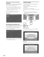
... HCE-C305R, you can select and switch image configurations. Rear View: Displays what is directly behind the car. The guidelines display varies with the image configuration. For details on how to switch image configurations, refer to view a wider than normal area behind the car. Use this icon is moving object verification icon may be different. f.::.:_ 10-EN Use this when you want to "Camera Operation...
... HCE-C305R, you can select and switch image configurations. Rear View: Displays what is directly behind the car. The guidelines display varies with the image configuration. For details on how to switch image configurations, refer to view a wider than normal area behind the car. Use this icon is moving object verification icon may be different. f.::.:_ 10-EN Use this when you want to "Camera Operation...

Owners Manual
Page 14
... calibration settings, refer to configure the guidance and install data. If there is an object on the downward slope, it is entered during the Calibration mode and ensures the most consistent detection results. Warning Message Displays This camera system displays warning messages in the upper part of the car on the screen if the system has not been calibrated. This data is necessary to "Calibration...
... calibration settings, refer to configure the guidance and install data. If there is an object on the downward slope, it is entered during the Calibration mode and ensures the most consistent detection results. Warning Message Displays This camera system displays warning messages in the upper part of the car on the screen if the system has not been calibrated. This data is necessary to "Calibration...

Owners Manual
Page 15
... screen. • Refer also to the Owners Manual of the product to display the camera image on the connected navigation/monitor. • Rear camera connection: ON setting Setting to ON is installed, actual conditions may be required depending on the navigation/monitor. • Camera guidelines display: OFF setting This camera system has its own, calibrated guidelines. Camera 0 eration Changing the Rear Image Configuration 1 Press VIEW. The image configuration changes every time VIEW...
... screen. • Refer also to the Owners Manual of the product to display the camera image on the connected navigation/monitor. • Rear camera connection: ON setting Setting to ON is installed, actual conditions may be required depending on the navigation/monitor. • Camera guidelines display: OFF setting This camera system has its own, calibrated guidelines. Camera 0 eration Changing the Rear Image Configuration 1 Press VIEW. The image configuration changes every time VIEW...
Owners Manual
Page 17
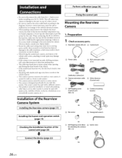
... case of the factory installed components (e.g. Preparation 1 Check accessory parts. ® CD Rearview camera (SO em) Control unit 0 ® Power cable @ RCA extension cable (3m) =[§] (Solderless connector) ® Camera extension cable (Bm) 00 ® Velcro fastener (Control unit) 0 Self-Tapping screw (Control unit) (M4x8) ® Camera mounting bracket Installation of the Rearview Camera System Installing the Rearview camera (page 17) Installing the buzzer and operation switch (page 19) Checking the installation location of the HCE-C305R has the...
... case of the factory installed components (e.g. Preparation 1 Check accessory parts. ® CD Rearview camera (SO em) Control unit 0 ® Power cable @ RCA extension cable (3m) =[§] (Solderless connector) ® Camera extension cable (Bm) 00 ® Velcro fastener (Control unit) 0 Self-Tapping screw (Control unit) (M4x8) ® Camera mounting bracket Installation of the Rearview Camera System Installing the Rearview camera (page 17) Installing the buzzer and operation switch (page 19) Checking the installation location of the HCE-C305R has the...

Owners Manual
Page 20
...@, and secure any dust, oil, etc., on the cable falling into the alarm unit. • If the alarm hole is closed off any slack cable around the waterproof pad @ using the cord clamp@. • Ensure the cable does not get the unit wet. Do not install in the car (under the seat, etc.) with the supplied cord clamp® . 19-EN 4 Secure the camera cable.
...@, and secure any dust, oil, etc., on the cable falling into the alarm unit. • If the alarm hole is closed off any slack cable around the waterproof pad @ using the cord clamp@. • Ensure the cable does not get the unit wet. Do not install in the car (under the seat, etc.) with the supplied cord clamp® . 19-EN 4 Secure the camera cable.
Owners Manual
Page 22
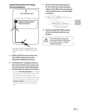
... HCE-C305R rearview camera mounting location (on rear bumper). a: Rubber grommet to pass camera wire from damage using split-loom tubing in injury or material property damages. 21-EN c: Connect the water-proof connector for Pickup Truck Installations t Front of pickup truck* Recommended camera power supply mounting location (inside of pickup truck cab to underside of pickup truck chassis. Special Instructions for the camera and camera extension cable...
... HCE-C305R rearview camera mounting location (on rear bumper). a: Rubber grommet to pass camera wire from damage using split-loom tubing in injury or material property damages. 21-EN c: Connect the water-proof connector for Pickup Truck Installations t Front of pickup truck* Recommended camera power supply mounting location (inside of pickup truck cab to underside of pickup truck chassis. Special Instructions for the camera and camera extension cable...
Owners Manual
Page 23
...plus side of the reverse lamp signal lead of the vehicle - - To Video Input Connector when connecting with the navigation or monitor that has no direct camera input connector I I SWITCH ® Dc Switch (Included) t I I BUZZER @ Buzzer extension cable (3m) (included) [J::::=:::tC::=[J I I CAMERA IN Camera extension Rearview camera cable (10m) (Included) (Included) [J::I VIDEO OUTPUT @ Ignition Key Battery - - Connections CD (Red) (Yellow) @ (Black) ACC @ I BATT I GND ® (Orange/White) I I REVERSE ® I I 0 (Orange/Black) CAMERA CONTROL I I ::R=E:A:R:tdll._:f_j_...
...plus side of the reverse lamp signal lead of the vehicle - - To Video Input Connector when connecting with the navigation or monitor that has no direct camera input connector I I SWITCH ® Dc Switch (Included) t I I BUZZER @ Buzzer extension cable (3m) (included) [J::::=:::tC::=[J I I CAMERA IN Camera extension Rearview camera cable (10m) (Included) (Included) [J::I VIDEO OUTPUT @ Ignition Key Battery - - Connections CD (Red) (Yellow) @ (Black) ACC @ I BATT I GND ® (Orange/White) I I REVERSE ® I I 0 (Orange/Black) CAMERA CONTROL I I ::R=E:A:R:tdll._:f_j_...
Owners Manual
Page 24
... (R). (J) Camera Control Lead Use to connect with products that do not have the camera screen display function other than the linkage with the navigation or monitor that lights when the transmission is shifted into the reverse position (R). ® Video Output Connector (Yellow) Connects to the plus side of the vehicle's battery. @Fuse 7.SA ® Ground Lead Connect this switch when calibration is performed. 23-EN Switches the video picture to...
... (R). (J) Camera Control Lead Use to connect with products that do not have the camera screen display function other than the linkage with the navigation or monitor that lights when the transmission is shifted into the reverse position (R). ® Video Output Connector (Yellow) Connects to the plus side of the vehicle's battery. @Fuse 7.SA ® Ground Lead Connect this switch when calibration is performed. 23-EN Switches the video picture to...
Owners Manual
Page 26
Refer to the Owner's Manual. 4 Make sure all factory components such as the seat raiL etc. Installing the Rearview camera:' (page 17) 2 Connect the battery(-) terminal. 3 Turn on the engine key. Make sure the unit is operating correctly by moving parts such as the brake lamps, etc., work correctly. 25-EN Also check for damage from sharp edges or protrusions. Make sure leads are not pinched by referring to "2. Confirmation 1 Securing leads, etc.
Refer to the Owner's Manual. 4 Make sure all factory components such as the seat raiL etc. Installing the Rearview camera:' (page 17) 2 Connect the battery(-) terminal. 3 Turn on the engine key. Make sure the unit is operating correctly by moving parts such as the brake lamps, etc., work correctly. 25-EN Also check for damage from sharp edges or protrusions. Make sure leads are not pinched by referring to "2. Confirmation 1 Securing leads, etc.
Owners Manual
Page 27
... calibration of the control unit to "OFF:' Setting ACC to configure the guidance and install data. Set the SETUP switch of the camera. Calibration must be performed. • If the vehicle height changes after calibration, the system must be re-calibrated. • Be sure the shift gear lever is Calibration? Switching between ~~calibration Mode" and 11Normal Use Mode" HCE-C305R has two modes: "Normal Use Mode" and "Calibration Mode:' You can be degraded. Preparation Accessory parts Calibration sheet CD Calibration sheet @ External...
... calibration of the control unit to "OFF:' Setting ACC to configure the guidance and install data. Set the SETUP switch of the camera. Calibration must be performed. • If the vehicle height changes after calibration, the system must be re-calibrated. • Be sure the shift gear lever is Calibration? Switching between ~~calibration Mode" and 11Normal Use Mode" HCE-C305R has two modes: "Normal Use Mode" and "Calibration Mode:' You can be degraded. Preparation Accessory parts Calibration sheet CD Calibration sheet @ External...
Owners Manual
Page 32
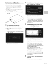
... VIEW, select 11Change" for (em) or (Inch), and press SET. Errors can result in the Top menu screen to align the end of the control unit to execute. If the area outside the camera range (black circle edge) might be saved. 1 Set the SETUP switch of the bumper The Top menu screen appears. to execute. 2 Set the ignition key to ACC ON. Performing Calibration • Measure and input calibration data carefully...
... VIEW, select 11Change" for (em) or (Inch), and press SET. Errors can result in the Top menu screen to align the end of the control unit to execute. If the area outside the camera range (black circle edge) might be saved. 1 Set the SETUP switch of the bumper The Top menu screen appears. to execute. 2 Set the ignition key to ACC ON. Performing Calibration • Measure and input calibration data carefully...
Owners Manual
Page 34
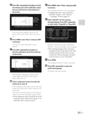
... adjust so that the bottom part of another connected device, set to execute. The screen will appear. • Language selection is also possible by selecting "Change" on the "Options" - If the warning message of this camera system overlaps the warning message of the calibration sheet lines up arrow, etc. 15 Press VIEW, select "Next:' and press SET. "Language" of the screen...
... adjust so that the bottom part of another connected device, set to execute. The screen will appear. • Language selection is also possible by selecting "Change" on the "Options" - If the warning message of this camera system overlaps the warning message of the calibration sheet lines up arrow, etc. 15 Press VIEW, select "Next:' and press SET. "Language" of the screen...
Owners Manual
Page 36
.... The connection is high, the screen may flicker. The video connection cable is difficult to the camera input of the camera is not correctly established. The control unit SETUP switch might be difficult to OFF. The rear camera image does not display, and the calibration mode appears. Turn the ignition key to OFF and then set to ON. The camera image sways. If a dark place or a partially bright light is captured...
.... The connection is high, the screen may flicker. The video connection cable is difficult to the camera input of the camera is not correctly established. The control unit SETUP switch might be difficult to OFF. The rear camera image does not display, and the calibration mode appears. Turn the ignition key to OFF and then set to ON. The camera image sways. If a dark place or a partially bright light is captured...

Owners Manual
Page 37
... changing the alarm volume. The alarm got louder or softer. The camera is not connected. Return to normal mode referring to a suitable level. Cause/Solution If there are noises on the radio, keep the camera cables and the video cables away from the actual distance, stop using this system and contact your ALPINE dealer. 36-EN Cause/Solution The reverse line is set the volume to ''Adjusting Alarm Volume...
... changing the alarm volume. The alarm got louder or softer. The camera is not connected. Return to normal mode referring to a suitable level. Cause/Solution If there are noises on the radio, keep the camera cables and the video cables away from the actual distance, stop using this system and contact your ALPINE dealer. 36-EN Cause/Solution The reverse line is set the volume to ''Adjusting Alarm Volume...

Owners Manual
Page 39
...-NAV-HELP (1-888-628-4357) Or visit our website at its option, repair or replace the product with a new or reconditioned product without Alpine's consent. ® Any product not distributed by over-driving the speaker (amplifier level is recommended to an Authorized Alpine Service Center or Alpine, Alpine will , at ; If the repairs are covered only in your Alpine car audio product has been installed...
...-NAV-HELP (1-888-628-4357) Or visit our website at its option, repair or replace the product with a new or reconditioned product without Alpine's consent. ® Any product not distributed by over-driving the speaker (amplifier level is recommended to an Authorized Alpine Service Center or Alpine, Alpine will , at ; If the repairs are covered only in your Alpine car audio product has been installed...


