TravelMate 6293 Service Guide
Page 7
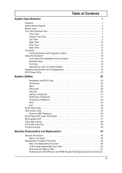
Table of Contents System Specifications 1 Features 1 System Block Diagram 4 Board Layort 5 Your Acer Notebook tour 7 Front View 7 Closed Front View 9 Left View 9 Right View 10 Rear View 10 Base View 11 Touchpad 12 Touchpad Basics (with ... SOP 37 Crisis disk creation 40 Crisis disk executing 44 Trouble shooting 45 Machine Disassembly and Replacement 47 General Information 48 Before You Begin 48 Disassembly Procedure Flowchart 49 Main unit disassembly flow chart 49 LCM module disassembly flow chart 50 Removing the Battery Pack 51 Removing the HDD/Wirless Card/RAM ...
Table of Contents System Specifications 1 Features 1 System Block Diagram 4 Board Layort 5 Your Acer Notebook tour 7 Front View 7 Closed Front View 9 Left View 9 Right View 10 Rear View 10 Base View 11 Touchpad 12 Touchpad Basics (with ... SOP 37 Crisis disk creation 40 Crisis disk executing 44 Trouble shooting 45 Machine Disassembly and Replacement 47 General Information 48 Before You Begin 48 Disassembly Procedure Flowchart 49 Main unit disassembly flow chart 49 LCM module disassembly flow chart 50 Removing the Battery Pack 51 Removing the HDD/Wirless Card/RAM ...
TravelMate 6293 Service Guide
Page 8
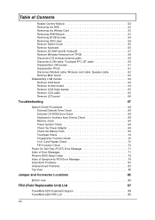
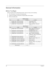
... TPCB 58 Disconnect 3G wireless antenna cable 59 Disconnect LCM cable, Touchpad FFC, BT cable 59 Disassemble LCM screws 61 Disassemble TPCB 61 Disconnect Modem cable, Wireless card cable, Speaker cable 62 Remove Main board 63 Disassembly LCM module 64 Remove LCM bezel 64 Remove Inverter board 64 Remove LCM hinge screws 65... Message 79 Intermittent Problems 83 Undetermined Problems 83 Top View 85 Jumper and Connector Locations 85 Bottom view 86 FRU (Field Replaceable Unit) List 87 TravelMate 6293 Exploded Diagram 88 TravelMate 6293 FRU List 89 VIII
... TPCB 58 Disconnect 3G wireless antenna cable 59 Disconnect LCM cable, Touchpad FFC, BT cable 59 Disassemble LCM screws 61 Disassemble TPCB 61 Disconnect Modem cable, Wireless card cable, Speaker cable 62 Remove Main board 63 Disassembly LCM module 64 Remove LCM bezel 64 Remove Inverter board 64 Remove LCM hinge screws 65... Message 79 Intermittent Problems 83 Undetermined Problems 83 Top View 85 Jumper and Connector Locations 85 Bottom view 86 FRU (Field Replaceable Unit) List 87 TravelMate 6293 Exploded Diagram 88 TravelMate 6293 FRU List 89 VIII
TravelMate 6293 Service Guide
Page 55
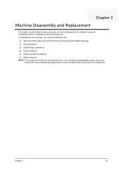
... ‰ Plastic tweezers NOTE: The screws for maintenance and troubleshooting. Chapter 3 47 During the disassembly process, group the screws with the corresponding components to disassemble the notebook computer TravelMate 6293 for the different components vary in size. Chapter 3 Machine Disassembly and Replacement This chapter contains step-by-step procedures on how to avoid mismatch when...
... ‰ Plastic tweezers NOTE: The screws for maintenance and troubleshooting. Chapter 3 47 During the disassembly process, group the screws with the corresponding components to disassemble the notebook computer TravelMate 6293 for the different components vary in size. Chapter 3 Machine Disassembly and Replacement This chapter contains step-by-step procedures on how to avoid mismatch when...
TravelMate 6293 Service Guide
Page 56
Unplug the AC adapter and all peripherals. 2. General Information Before You Begin Before proceeding with the disassembly procedure, make sure that you do the following: 1. Turn off the power to the system and all power and signal cables from the system. 3. SPEC ...
Unplug the AC adapter and all peripherals. 2. General Information Before You Begin Before proceeding with the disassembly procedure, make sure that you do the following: 1. Turn off the power to the system and all power and signal cables from the system. 3. SPEC ...
TravelMate 6293 Service Guide
Page 57
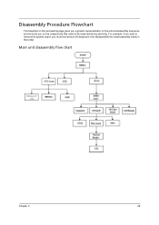
Disassembly Procedure Flowchart The flowchart on the succeeding page gives you a graphic representation on the entire disassembly sequence and instructs you must first remove the keyboard, then disassemble the inside assembly frame in that need to remove the system board, you on the components that order. For example, if you want to be removed during servicing. Main unit disassembly flow chart Chapter 3 49
Disassembly Procedure Flowchart The flowchart on the succeeding page gives you a graphic representation on the entire disassembly sequence and instructs you must first remove the keyboard, then disassemble the inside assembly frame in that need to remove the system board, you on the components that order. For example, if you want to be removed during servicing. Main unit disassembly flow chart Chapter 3 49
TravelMate 6293 Service Guide
Page 72
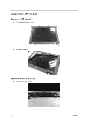
Remove LCM bezel. Remove Inverter board 5. Remove six LCM bezel mylar. 4. Disconnect Inverter cables. 64 Chapter 3 Disassembly LCM module Remove LCM bezel 3.
Remove LCM bezel. Remove Inverter board 5. Remove six LCM bezel mylar. 4. Disconnect Inverter cables. 64 Chapter 3 Disassembly LCM module Remove LCM bezel 3.


