TravelMate 290 Service Guide
Page 7
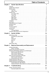
... 38 Boot 40 Exit 41 BIOS Flash Utility 42 System Diagnostic Diskette 42 Chapter 3 Machine Disassembly and Replacement 43 General Information 44 Before You Begin 44 Disassembly Procedure Flowchart 45 Removing ODD Module, Memory and HDD Module 48 Removing the ODD Module 48...48 Removing the Keyboard/LCD Module 49 Removing the Keyboard 49 Removing the LCD module 49 Disassembling the Main Unit 51 Disassembling the LCD Module 57 Disassembling the External Modules 59 Disassembling the HDD Module 59 Disassembling the Optical Disk Drive Module/Combo Drive Module . . . . .59 Chapter 4...
... 38 Boot 40 Exit 41 BIOS Flash Utility 42 System Diagnostic Diskette 42 Chapter 3 Machine Disassembly and Replacement 43 General Information 44 Before You Begin 44 Disassembly Procedure Flowchart 45 Removing ODD Module, Memory and HDD Module 48 Removing the ODD Module 48...48 Removing the Keyboard/LCD Module 49 Removing the Keyboard 49 Removing the LCD module 49 Disassembling the Main Unit 51 Disassembling the LCD Module 57 Disassembling the External Modules 59 Disassembling the HDD Module 59 Disassembling the Optical Disk Drive Module/Combo Drive Module . . . . .59 Chapter 4...

TravelMate 290 Service Guide
Page 51
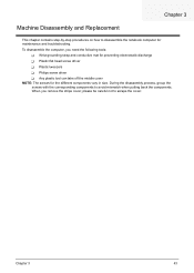
... computer, you remove the stripe cover, please be careful not to avoid mismatch when putting back the components. Chapter 3 43 During the disassembly process, group the screws with the corresponding components to scrape the cover. When you need the following tools: T Wrist grounding strap and conductive mat for ... screw driver T Plastic tweezers T Philips screw driver T Any plastic tool can take off the middle cover NOTE: The screws for maintenance and troubleshooting. Chapter 3 Machine Disassembly and Replacement This chapter contains step-by-step procedures on how to...
... computer, you remove the stripe cover, please be careful not to avoid mismatch when putting back the components. Chapter 3 43 During the disassembly process, group the screws with the corresponding components to scrape the cover. When you need the following tools: T Wrist grounding strap and conductive mat for ... screw driver T Plastic tweezers T Philips screw driver T Any plastic tool can take off the middle cover NOTE: The screws for maintenance and troubleshooting. Chapter 3 Machine Disassembly and Replacement This chapter contains step-by-step procedures on how to...

TravelMate 290 Service Guide
Page 52
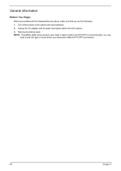
Remove the battery pack. General Information Before You Begin Before proceeding with the disassembly procedure, make sure that you disconnect different FFC/FPC/connectors. 44 Chapter 3 NOTE: TravelMate 290 series product uses mylar or tape to fasten the FFC/FPC/connectors/cable, you may need to the system and all power and signal cables from the system. 3. Unplug the AC adapter and all peripherals. 2. Turn off the power to tear the tape or mylar before you do the following: 1.
Remove the battery pack. General Information Before You Begin Before proceeding with the disassembly procedure, make sure that you disconnect different FFC/FPC/connectors. 44 Chapter 3 NOTE: TravelMate 290 series product uses mylar or tape to fasten the FFC/FPC/connectors/cable, you may need to the system and all power and signal cables from the system. 3. Unplug the AC adapter and all peripherals. 2. Turn off the power to tear the tape or mylar before you do the following: 1.
TravelMate 290 Service Guide
Page 53
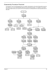
... you want to remove the system board, you on the components that order. Disassembly Procedure Flowchart The flowchart on the succeeding page gives you a graphic representation on the entire disassembly sequence and instructs you must first remove the keyboard, then disassemble the inside assembly frame in that need to be removed during servicing.
... you want to remove the system board, you on the components that order. Disassembly Procedure Flowchart The flowchart on the succeeding page gives you a graphic representation on the entire disassembly sequence and instructs you must first remove the keyboard, then disassemble the inside assembly frame in that need to be removed during servicing.

TravelMate 290 Service Guide
Page 59
... the order as shown. Remove the screw holding the launch board. 6. Take off the launch board. 7. Remove the two screws that secures the thermal plate. 8. Disassembling the Main Unit 1. Disconnect the touchpad FPC. 3. Disconnect the fan cable. 13. Remove the screw that fastens the power buttom. 4. See "Removing the Keyboard/LCD...
... the order as shown. Remove the screw holding the launch board. 6. Take off the launch board. 7. Remove the two screws that secures the thermal plate. 8. Disassembling the Main Unit 1. Disconnect the touchpad FPC. 3. Disconnect the fan cable. 13. Remove the screw that fastens the power buttom. 4. See "Removing the Keyboard/LCD...

TravelMate 290 Service Guide
Page 65
Remove the two LCD rubber feet and the two screw caps. 2. Tear off the tape fastening the inverter connector. 5. Remove the two screws holding the LCD inverter board. 7. Remove the four screws that fasten the LCD bezel. 3. Detach the LCD bezel carefully. 4. Disconnect the inverter board connector. 9. Chapter 3 57 Tear off the tape fastening the inverter cable. 6. one on each side. 10. Remove the screw holding the LCD; Then remove the LCD from the LCD panel. . Disconnect the high voltage cable and the inverter board. 8. Disassembling the LCD Module 1.
Remove the two LCD rubber feet and the two screw caps. 2. Tear off the tape fastening the inverter connector. 5. Remove the two screws holding the LCD inverter board. 7. Remove the four screws that fasten the LCD bezel. 3. Detach the LCD bezel carefully. 4. Disconnect the inverter board connector. 9. Chapter 3 57 Tear off the tape fastening the inverter cable. 6. one on each side. 10. Remove the screw holding the LCD; Then remove the LCD from the LCD panel. . Disconnect the high voltage cable and the inverter board. 8. Disassembling the LCD Module 1.

TravelMate 290 Service Guide
Page 67
... holder. 5. Remove the two screws holding the HDD carrier on the other side. 3. Detach the HDD cover. Then remove the optical device board. Disassembling the External Modules Disassembling the HDD Module 1. Remove the the optical device bracket. 6. Then remove the last two screws that fasten the optical device holder on the other...
... holder. 5. Remove the two screws holding the HDD carrier on the other side. 3. Detach the HDD cover. Then remove the optical device board. Disassembling the External Modules Disassembling the HDD Module 1. Remove the the optical device bracket. 6. Then remove the last two screws that fasten the optical device holder on the other...

TravelMate 290 Service Guide
Page 74
... through the sub-steps under step 2. Replace the CPU with another of earphone or external speakers. Replace main board. 3. Replace the main board. 3. Follow the disassembling steps in speakers are functioning properly, perform the following steps. The main board may be damaged. Please insert the diagnostic disk and run the display...
... through the sub-steps under step 2. Replace the CPU with another of earphone or external speakers. Replace main board. 3. Replace the main board. 3. Follow the disassembling steps in speakers are functioning properly, perform the following steps. The main board may be damaged. Please insert the diagnostic disk and run the display...
TravelMate 290 Service Guide
Page 113
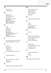
...Utility 33 Basic System Settings 35 Navigating 33 Startup Configuration 38 System Information 34 System Security 34, 41 D DIMM external 48 removing 48 Disassembly Battery Pack 46 CD-ROM/DVD-ROM Module 51 Floppy Disk Drive 57 Machine 43 Procedure Flowchart 45 E Error Symptom-to-Spare Part ... 79 I Intermittent Problems 72 J Jumper and Connector Locations 75 Top View 75 K Index Index Keyboard or Auxiliary Input Device Check 63 M Machine Disassembly 43 Memory Check 63 Model Definition 94 Modem Combo Card external 49 O Online Support Information 103 P Panel Bottom 11 Power System Check Battery Pack ...
...Utility 33 Basic System Settings 35 Navigating 33 Startup Configuration 38 System Information 34 System Security 34, 41 D DIMM external 48 removing 48 Disassembly Battery Pack 46 CD-ROM/DVD-ROM Module 51 Floppy Disk Drive 57 Machine 43 Procedure Flowchart 45 E Error Symptom-to-Spare Part ... 79 I Intermittent Problems 72 J Jumper and Connector Locations 75 Top View 75 K Index Index Keyboard or Auxiliary Input Device Check 63 M Machine Disassembly 43 Memory Check 63 Model Definition 94 Modem Combo Card external 49 O Online Support Information 103 P Panel Bottom 11 Power System Check Battery Pack ...

TravelMate 290 User's Guide
Page 76
Do not disassemble or dispose of them away from children and dispose of used with the same type as the product's battery we recommend. It should be a detachable ...
Do not disassemble or dispose of them away from children and dispose of used with the same type as the product's battery we recommend. It should be a detachable ...

TravelMate 290 User's Guide
Page 78
... the manufacturer's instructions. Note: Below regulatory information is for models with a telecommunications compliance label. This device complies with high-precision manufacturing techniques. Reverse engineering or disassembly is intended for limited viewing uses only. patents and other rights owners. This includes customer equipment previously labelled permitted or certified. Macrovision copyright protection notice...
... the manufacturer's instructions. Note: Below regulatory information is for models with a telecommunications compliance label. This device complies with high-precision manufacturing techniques. Reverse engineering or disassembly is intended for limited viewing uses only. patents and other rights owners. This includes customer equipment previously labelled permitted or certified. Macrovision copyright protection notice...
TravelMate 290E Service Guide
Page 7
...Main 34 Advanced 35 Security 38 Boot 40 Exit 41 BIOS Flash Utility 42 Chapter 3 Machine Disassembly and Replacement 43 General Information 44 Before You Begin 44 Disassembly Procedure Flowchart 45 Removing ODD Module, Memory and HDD Module 48 Removing the ODD Module 48... Keyboard/LCD Module 49 Removing the Keyboard 49 Removing the LCD module 49 Disassembling the Main Unit 51 Disassembling the LCD Module 57 Disassembling the External Modules 59 Disassembling the HDD Module 59 Disassembling the Optical Disk Drive Module/Combo Drive Module 59 Chapter 4 Troubleshooting 61 ...
...Main 34 Advanced 35 Security 38 Boot 40 Exit 41 BIOS Flash Utility 42 Chapter 3 Machine Disassembly and Replacement 43 General Information 44 Before You Begin 44 Disassembly Procedure Flowchart 45 Removing ODD Module, Memory and HDD Module 48 Removing the ODD Module 48... Keyboard/LCD Module 49 Removing the Keyboard 49 Removing the LCD module 49 Disassembling the Main Unit 51 Disassembling the LCD Module 57 Disassembling the External Modules 59 Disassembling the HDD Module 59 Disassembling the Optical Disk Drive Module/Combo Drive Module 59 Chapter 4 Troubleshooting 61 ...
TravelMate 290E Service Guide
Page 51
... computer, you remove the stripe cover, please be careful not to scrape the cover. During the disassembly process, group the screws with the corresponding components to avoid mismatch when putting back the components. Chapter 3 43 When you need the following tools: T Wrist ... screw driver T Plastic tweezers T Philips screw driver T Any plastic tool can take off the middle cover NOTE: The screws for maintenance and troubleshooting. Chapter 3 Machine Disassembly and Replacement This chapter contains step-by-step procedures on how to...
... computer, you remove the stripe cover, please be careful not to scrape the cover. During the disassembly process, group the screws with the corresponding components to avoid mismatch when putting back the components. Chapter 3 43 When you need the following tools: T Wrist ... screw driver T Plastic tweezers T Philips screw driver T Any plastic tool can take off the middle cover NOTE: The screws for maintenance and troubleshooting. Chapter 3 Machine Disassembly and Replacement This chapter contains step-by-step procedures on how to...
TravelMate 290E Service Guide
Page 52
Remove the battery pack. General Information Before You Begin Before proceeding with the disassembly procedure, make sure that you disconnect different FFC/FPC/connectors. 44 Chapter 3 Unplug the AC adapter and all peripherals. 2. NOTE: TravelMate 290E series product uses mylar or tape to fasten the FFC/FPC/connectors/cable, you may need to the system and all power and signal cables from the system. 3. Turn off the power to tear the tape or mylar before you do the following: 1.
Remove the battery pack. General Information Before You Begin Before proceeding with the disassembly procedure, make sure that you disconnect different FFC/FPC/connectors. 44 Chapter 3 Unplug the AC adapter and all peripherals. 2. NOTE: TravelMate 290E series product uses mylar or tape to fasten the FFC/FPC/connectors/cable, you may need to the system and all power and signal cables from the system. 3. Turn off the power to tear the tape or mylar before you do the following: 1.

TravelMate 290E Service Guide
Page 53
... Shielding P*4 Speaker Set Touchpad Main Board F*2 I*2 PCMCIA Slot Lower Case Chapter 3 45 Disassembly Procedure Flowchart The flowchart on the succeeding page gives you a graphic representation on the entire disassembly sequence and instructs you on the components that order. For example, if you must first remove... the keyboard, then disassemble the inside assembly frame in that need to remove the system board...
... Shielding P*4 Speaker Set Touchpad Main Board F*2 I*2 PCMCIA Slot Lower Case Chapter 3 45 Disassembly Procedure Flowchart The flowchart on the succeeding page gives you a graphic representation on the entire disassembly sequence and instructs you on the components that order. For example, if you must first remove... the keyboard, then disassemble the inside assembly frame in that need to remove the system board...

TravelMate 290E Service Guide
Page 59
... remove the screw that secures the thermal plate. 8. Disconnect the touchpad FPC. 3. Disconnect the fan cable. 13. Then take off the power button. 5. Chapter 3 51 Disassembling the Main Unit 1. Disconnect the modem card cable. 12. Remove the four screws according to the order as shown.
... remove the screw that secures the thermal plate. 8. Disconnect the touchpad FPC. 3. Disconnect the fan cable. 13. Then take off the power button. 5. Chapter 3 51 Disassembling the Main Unit 1. Disconnect the modem card cable. 12. Remove the four screws according to the order as shown.

TravelMate 290E Service Guide
Page 65
Detach the LCD bezel carefully. 4. Then remove the LCD from the LCD panel. . Chapter 3 57 Disassembling the LCD Module 1. Tear off the tape fastening the inverter cable. 6. Remove the two LCD rubber feet and the two screw caps. 2. Remove the screw holding the LCD; Remove the two screws holding the LCD inverter board. 7. Disconnect the inverter board connector. 9. Disconnect the high voltage cable and the inverter board. 8. Tear off the tape fastening the inverter connector. 5. Remove the four screws that fasten the LCD bezel. 3. one on each side. 10.
Detach the LCD bezel carefully. 4. Then remove the LCD from the LCD panel. . Chapter 3 57 Disassembling the LCD Module 1. Tear off the tape fastening the inverter cable. 6. Remove the two LCD rubber feet and the two screw caps. 2. Remove the screw holding the LCD; Remove the two screws holding the LCD inverter board. 7. Disconnect the inverter board connector. 9. Disconnect the high voltage cable and the inverter board. 8. Tear off the tape fastening the inverter connector. 5. Remove the four screws that fasten the LCD bezel. 3. one on each side. 10.

TravelMate 290E Service Guide
Page 67
...two screws that fasten the optical device holder on the other side. 3. Then remove another two screws that secure the holder. 4. Disassembling the Optical Disk Drive Module/Combo Drive Module 1. Take the optical disc drive from the optical device holder. 5. Remove the optical ...device bracket. 6. Remove another two screws fastening the HDD carrier on the other side. 3. Disassembling the External Modules Disassembling the HDD Module 1. Detach the HDD cover. Remove the two screws holding the optical device holder. 2. Then remove the...
...two screws that fasten the optical device holder on the other side. 3. Then remove another two screws that secure the holder. 4. Disassembling the Optical Disk Drive Module/Combo Drive Module 1. Take the optical disc drive from the optical device holder. 5. Remove the optical ...device bracket. 6. Remove another two screws fastening the HDD carrier on the other side. 3. Disassembling the External Modules Disassembling the HDD Module 1. Detach the HDD cover. Remove the two screws holding the optical device holder. 2. Then remove the...

TravelMate 290E Service Guide
Page 74
... test program and go to next step. Try different audio sources. If these devices work fine, go through the sub-steps under step 2. Follow the disassembling steps in the source devices. If not all have sound problem, the problem is in speakers are functioning properly, perform the following steps. If the...
... test program and go to next step. Try different audio sources. If these devices work fine, go through the sub-steps under step 2. Follow the disassembling steps in the source devices. If not all have sound problem, the problem is in speakers are functioning properly, perform the following steps. If the...
TravelMate 290E Service Guide
Page 113
...Utility 33 Basic System Settings 35 Navigating 33 Startup Configuration 38 System Information 34 System Security 34, 41 D DIMM external 48 removing 48 Disassembly Battery Pack 46 CD-ROM/DVD-ROM Module 51 Floppy Disk Drive 57 Machine 43 Procedure Flowchart 45 E Error Symptom-to-Spare Part ... I Intermittent Problems 72 J Jumper and Connector Locations 75 Top View 75 Bottom View 77 K Keyboard or Auxiliary Input Device Check 63 M Machine Disassembly 43 Memory Check 63 Model Definition 94 Modem Combo Card external 49 O Online Support Information 103 P Panel Bottom 11 Power System Check Battery Pack ...
...Utility 33 Basic System Settings 35 Navigating 33 Startup Configuration 38 System Information 34 System Security 34, 41 D DIMM external 48 removing 48 Disassembly Battery Pack 46 CD-ROM/DVD-ROM Module 51 Floppy Disk Drive 57 Machine 43 Procedure Flowchart 45 E Error Symptom-to-Spare Part ... I Intermittent Problems 72 J Jumper and Connector Locations 75 Top View 75 Bottom View 77 K Keyboard or Auxiliary Input Device Check 63 M Machine Disassembly 43 Memory Check 63 Model Definition 94 Modem Combo Card external 49 O Online Support Information 103 P Panel Bottom 11 Power System Check Battery Pack ...


