TravelMate 2310 Service Guide
Page 40
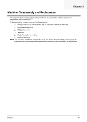
... T Flat-bladed screw driver T Phillips screw driver T Tweezers T Plastic Flat-bladed screw driver T Hexed Screw Driver NOTE: The screws for maintenance and troubleshooting. Chapter 3 Machine Disassembly and Replacement This chapter contains step-by-step procedures on how to avoid mismatch when putting back the components. During the...
... T Flat-bladed screw driver T Phillips screw driver T Tweezers T Plastic Flat-bladed screw driver T Hexed Screw Driver NOTE: The screws for maintenance and troubleshooting. Chapter 3 Machine Disassembly and Replacement This chapter contains step-by-step procedures on how to avoid mismatch when putting back the components. During the...
TravelMate 2310 Service Guide
Page 41
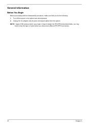
General Information Before You Begin Before proceeding with the disassembly procedure, make sure that you disconnect different FFC/FPC/connectors. 47 Chapter 3 NOTE: Aspire 9100 series product uses mylar or tape to fasten the FFC/FPC/connectors/cable, you may need to the system and all power and signal cables from the system . Turn off the power to tear the tape or mylar before you do the following: 1. Unplug the AC adapter and all peripherals. 2.
General Information Before You Begin Before proceeding with the disassembly procedure, make sure that you disconnect different FFC/FPC/connectors. 47 Chapter 3 NOTE: Aspire 9100 series product uses mylar or tape to fasten the FFC/FPC/connectors/cable, you may need to the system and all power and signal cables from the system . Turn off the power to tear the tape or mylar before you do the following: 1. Unplug the AC adapter and all peripherals. 2.
TravelMate 2310 Service Guide
Page 42
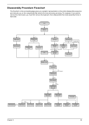
... B*5 E*16+B*2 Lower and Upper Case Assembly Lower Case Assembly *3 VGA Heatsink E*2 *2 screw nuts Main Board 3-in that order. Disassembly Procedure Flowchart The flowchart on the succeeding page gives you a graphic representation on the components that need to remove the main board, you... on the entire disassembly sequence and instructs you must first remove the keyboard, then disassemble the inside assembly frame in -1 Cover *4 Speaker Set B*2 Modem Board Upper Case Assembly Touchpad Touchpad...
... B*5 E*16+B*2 Lower and Upper Case Assembly Lower Case Assembly *3 VGA Heatsink E*2 *2 screw nuts Main Board 3-in that order. Disassembly Procedure Flowchart The flowchart on the succeeding page gives you a graphic representation on the components that need to remove the main board, you... on the entire disassembly sequence and instructs you must first remove the keyboard, then disassemble the inside assembly frame in -1 Cover *4 Speaker Set B*2 Modem Board Upper Case Assembly Touchpad Touchpad...

TravelMate 2310 Service Guide
Page 49
Disassembling the Upper Case Assembly 1. Then detach the touchpad board to touchpad FFC. 2. Disconnect the microphone cable then remove the upper case assembly. Disconnect the touchpad ... touchpad board. 55 Chapter 3 Disconnect the touchpad board to main board FFC from the main board. 4. Disconnect the touchpad board to the lower case assembly. 8. Disassembling the Main Unit Separate the Main Unit Into the Upper and the Lower Case Assembly 1. Disconnect the bluetooth cable. 5. Remove the five screws that secure...
Disassembling the Upper Case Assembly 1. Then detach the touchpad board to touchpad FFC. 2. Disconnect the microphone cable then remove the upper case assembly. Disconnect the touchpad ... touchpad board. 55 Chapter 3 Disconnect the touchpad board to main board FFC from the main board. 4. Disconnect the touchpad board to the lower case assembly. 8. Disassembling the Main Unit Separate the Main Unit Into the Upper and the Lower Case Assembly 1. Disconnect the bluetooth cable. 5. Remove the five screws that secure...

TravelMate 2310 Service Guide
Page 50
... assembly. 8. 4. Remove the touchpad board to touchpad FFC. 7. Disconnect the MDC cable from the upper case. 6. Remove the two screws that secure the touchpad board. 5. Disassembling the Lower Case Assembly 1. Disconnect the bluetooth module then remove it. Remove the three screws that secure the bluetooth module. 12. Remove the touchpad board...
... assembly. 8. 4. Remove the touchpad board to touchpad FFC. 7. Disconnect the MDC cable from the upper case. 6. Remove the two screws that secure the touchpad board. 5. Disassembling the Lower Case Assembly 1. Disconnect the bluetooth module then remove it. Remove the three screws that secure the bluetooth module. 12. Remove the touchpad board...
TravelMate 2310 Service Guide
Page 52
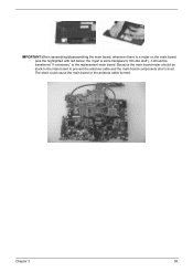
the mylar is a mylar on the main board (see the highlighted with red below; Because the main board mylar should be stuck to the main board to the replacement main board. Chapter 3 58 The short could cause the main board or the antenna cable burned. IMPORTANT:When assembling/disassembling the main board, whenever there is sami-transparent, film-like stuff ), it should be transferred "if necessary" to prevent the antenna cable and the main board components short circuit.
the mylar is a mylar on the main board (see the highlighted with red below; Because the main board mylar should be stuck to the main board to the replacement main board. Chapter 3 58 The short could cause the main board or the antenna cable burned. IMPORTANT:When assembling/disassembling the main board, whenever there is sami-transparent, film-like stuff ), it should be transferred "if necessary" to prevent the antenna cable and the main board components short circuit.
TravelMate 2310 Service Guide
Page 53
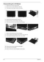
Disassembling the LCD Module 1. Then remove the three screws that secure the LCD bracket. 8. Then detach the LCD panel from the LCD module. 4. Remove the three ...
Disassembling the LCD Module 1. Then remove the three screws that secure the LCD bracket. 8. Then detach the LCD panel from the LCD module. 4. Remove the three ...

TravelMate 2310 Service Guide
Page 55
Disassembling the Optical Drive Module 1. Remove the four screws as shown. 4. Push the ODD holder as the picture shows. 2. Disconnect the ODD connector board then remove it. 61 Chapter 3 Remove the two screws holding the HDD bracket on one side. 2. Detach the ODD holder. 5. Remove another two screws holding the HDD bracket on the other side. 3. Disassembling the External Modules Disassembling the HDD Module 1. Remove the two screws that secure the optical disc drive and the ODD holder. 3. Then take the hard disc drive out from the HDD bracket.
Disassembling the Optical Drive Module 1. Remove the four screws as shown. 4. Push the ODD holder as the picture shows. 2. Disconnect the ODD connector board then remove it. 61 Chapter 3 Remove the two screws holding the HDD bracket on one side. 2. Detach the ODD holder. 5. Remove another two screws holding the HDD bracket on the other side. 3. Disassembling the External Modules Disassembling the HDD Module 1. Remove the two screws that secure the optical disc drive and the ODD holder. 3. Then take the hard disc drive out from the HDD bracket.

TravelMate 2310 User's Guide
Page 61
... When the power cord or plug is properly grounded. 15 Use only the proper type of electric shock from the wall outlet before serving or disassembling this product yourself, as the product's battery we recommend in your accessories box) for service. 12 The notebook PC series uses lithium batteries. ...c If the product has been exposed to service this equipment. 17 Avoid using a telephone (other risks. Do not disassemble or dispose of any kind on the product. 10 Do not attempt to rain or water. Never spill liquid of them away from the ...
... When the power cord or plug is properly grounded. 15 Use only the proper type of electric shock from the wall outlet before serving or disassembling this product yourself, as the product's battery we recommend in your accessories box) for service. 12 The notebook PC series uses lithium batteries. ...c If the product has been exposed to service this equipment. 17 Avoid using a telephone (other risks. Do not disassemble or dispose of any kind on the product. 10 Do not attempt to rain or water. Never spill liquid of them away from the ...

TravelMate 2310 User's Guide
Page 63
... with wireless LAN and/or Bluetooth only. Depending on configurations, this copyright protection technology must be authorized by Macrovision, and is prohibited. Reverse engineering or disassembly is intended for models with the radio frequency and safety standards of this product may or may not contain wireless radio devices (such as wireless...
... with wireless LAN and/or Bluetooth only. Depending on configurations, this copyright protection technology must be authorized by Macrovision, and is prohibited. Reverse engineering or disassembly is intended for models with the radio frequency and safety standards of this product may or may not contain wireless radio devices (such as wireless...


