
User Manual
Page 11
TMDS Data 2/4 Shield 15. NC 16. NC 20. NC 24. Logic Ground 4. NC 17. TMDS Data 0/5 Shield 8. TMDS Data1- 21. NC 2. Hot Plug Detect 5. DDC Data 19. TMDS Clock Shield 11. NC 9. TMDS Clock+ 12. TMDS Data2- 13. TMDS Data0- 6. TMDS Data2+ 14. +5V Power 3. TMDS Data0+ 7. NC 10. DDC Clock 18. TMDS Data 1/3 Shield 23. 24-Pin Color Display Signal Cable* PIN Meaning PIN Meaning 1. TMDS Data1+ 22. DDC TMDS Clock- * only for certain models EN-10
TMDS Data 2/4 Shield 15. NC 16. NC 20. NC 24. Logic Ground 4. NC 17. TMDS Data 0/5 Shield 8. TMDS Data1- 21. NC 2. Hot Plug Detect 5. DDC Data 19. TMDS Clock Shield 11. NC 9. TMDS Clock+ 12. TMDS Data2- 13. TMDS Data0- 6. TMDS Data2+ 14. +5V Power 3. TMDS Data0+ 7. NC 10. DDC Clock 18. TMDS Data 1/3 Shield 23. 24-Pin Color Display Signal Cable* PIN Meaning PIN Meaning 1. TMDS Data1+ 22. DDC TMDS Clock- * only for certain models EN-10
User Manual
Page 21
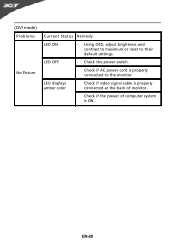
(DVI mode) Problems No Picture Current Status Remedy LED ON · Using OSD, adjust brightness and contrast to maximum or reset to the monitor. LED displays amber color · Check if video signal cable is properly connected at the back of monitor. · Check if the power of computer system is properly connected to their default settings. EN-20 LED OFF · Check the power switch. · Check if AC power cord is ON.
(DVI mode) Problems No Picture Current Status Remedy LED ON · Using OSD, adjust brightness and contrast to maximum or reset to the monitor. LED displays amber color · Check if video signal cable is properly connected at the back of monitor. · Check if the power of computer system is properly connected to their default settings. EN-20 LED OFF · Check the power switch. · Check if AC power cord is ON.


