Altos G540 User's Guide EN
Page 6
... unit. f If the product exhibits a distinct change in your area. 14 Use only the proper type of fire or explosion. Batteries may present a risk of power supply cord set (provided in performance, indicating a need for this product from children. Promptly dispose used batteries according to regulations applicable to qualified service personnel under...
... unit. f If the product exhibits a distinct change in your area. 14 Use only the proper type of fire or explosion. Batteries may present a risk of power supply cord set (provided in performance, indicating a need for this product from children. Promptly dispose used batteries according to regulations applicable to qualified service personnel under...
Altos G540 User's Guide EN
Page 7
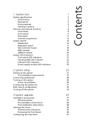
... module 20 System LED indicators 21 Front panel LED indicators 21 Hot-plug HDD LED indicator 22 LAN port LED indicators 22 Power supply module LED indicators 23 2 System setup 25 Setting up the system 27 Pre-installation requirements 27 Connecting peripherals 28 Turning on the ...system 29 Power-on problems 30 Configuring the system OS 31 Rack mount configuration 32 Turning off the system 33 3 System upgrade 35 Installation precautions...
... module 20 System LED indicators 21 Front panel LED indicators 21 Hot-plug HDD LED indicator 22 LAN port LED indicators 22 Power supply module LED indicators 23 2 System setup 25 Setting up the system 27 Pre-installation requirements 27 Connecting peripherals 28 Turning on the ...system 29 Power-on problems 30 Configuring the system OS 31 Rack mount configuration 32 Turning off the system 33 3 System upgrade 35 Installation precautions...
Altos G540 User's Guide EN
Page 8
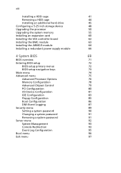
... memory 55 Installing an expansion card 60 Installing the SAS controller board 62 Installing the BMC module 63 Installing the ARMC/3 module 64 Installing a redundant power supply module 66 4 System BIOS 69 BIOS overview 71 Entering BIOS setup 72 BIOS setup primary menus 72 BIOS setup navigation keys 73 Main menu 74...
... memory 55 Installing an expansion card 60 Installing the SAS controller board 62 Installing the BMC module 63 Installing the ARMC/3 module 64 Installing a redundant power supply module 66 4 System BIOS 69 BIOS overview 71 Entering BIOS setup 72 BIOS setup primary menus 72 BIOS setup navigation keys 73 Main menu 74...

Altos G540 User's Guide EN
Page 15
... • Parallel port • Four rear USB 2.0 ports • Two Gigabit LAN ports (RJ-45) Power supply and system fan • 610-watts power supply with redundant option • System fan with redundant option Hardware monitoring and server management • Winbond W83792D hardware... monitoring IC for voltage, temperature, and fan speed detection • LED indicators for constant monitoring of basic system function • Acer ...
... • Parallel port • Four rear USB 2.0 ports • Two Gigabit LAN ports (RJ-45) Power supply and system fan • 610-watts power supply with redundant option • System fan with redundant option Hardware monitoring and server management • Winbond W83792D hardware... monitoring IC for voltage, temperature, and fan speed detection • LED indicators for constant monitoring of basic system function • Acer ...
Altos G540 User's Guide EN
Page 17
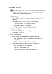
...- IPMI (Intelligent Platform Management Interface) 2.0 compliant - 7 Hardware options Note: To purchase the any of the following hardware options, contact your local Acer representative. • Media storage • LSI 1068 SAS controller board provides both SAS and SATA2 support • LSI MegaRAID SAS RAID controller board ...Backup battery unit (BBU) option • Ultra 320 SCSI HBA (for backup devices only) • Redundant modules • Hot-swap redundant power supply • Redundant system fan • Server management • BMC (Baseboard Management Controller) module -
...- IPMI (Intelligent Platform Management Interface) 2.0 compliant - 7 Hardware options Note: To purchase the any of the following hardware options, contact your local Acer representative. • Media storage • LSI 1068 SAS controller board provides both SAS and SATA2 support • LSI MegaRAID SAS RAID controller board ...Backup battery unit (BBU) option • Ultra 320 SCSI HBA (for backup devices only) • Redundant modules • Hot-swap redundant power supply • Redundant system fan • Server management • BMC (Baseboard Management Controller) module -
Altos G540 User's Guide EN
Page 21
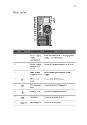
PS/2 mouse port Connects to serial devices. Serial port Connects to a PS/2 mouse. 11 Rear panel No. Icon 1 2 3 4 5 6 7 8 Component Description Power supply module release latch Push down the latch to parallel devices. Power supply module cord socket Connect the system power cord here. Main power Provides the system's main power supply module supply. port Parallel port Connects to disengage the module from the chassis. PS/2 keyboard Connects to monitors. Monitor port Connects to a PS/2 keyboard.
PS/2 mouse port Connects to serial devices. Serial port Connects to a PS/2 mouse. 11 Rear panel No. Icon 1 2 3 4 5 6 7 8 Component Description Power supply module release latch Push down the latch to parallel devices. Power supply module cord socket Connect the system power cord here. Main power Provides the system's main power supply module supply. port Parallel port Connects to disengage the module from the chassis. PS/2 keyboard Connects to monitors. Monitor port Connects to a PS/2 keyboard.
Altos G540 User's Guide EN
Page 22
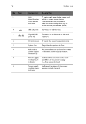
... indicator Indicates the occurrence of a fault condition in the power supply module. (green/amber) Power supply module status indicator Indicates the status of identification during servicing or maintenance procedures. (blue) Connects to USB devices. PCI ... ports 1/2 Connects to mark a particular server unit within a server group (when rack-mounted) for purpose of the power supply module. (green) Redundant power supply module bay Accommodates an optional hot-swap redundant power supply module. 12 No. Icon 9 10 11 12 13 14 15 16 1 System tour Component Unit identification (UID)...
... indicator Indicates the occurrence of a fault condition in the power supply module. (green/amber) Power supply module status indicator Indicates the status of identification during servicing or maintenance procedures. (blue) Connects to USB devices. PCI ... ports 1/2 Connects to mark a particular server unit within a server group (when rack-mounted) for purpose of the power supply module. (green) Redundant power supply module bay Accommodates an optional hot-swap redundant power supply module. 12 No. Icon 9 10 11 12 13 14 15 16 1 System tour Component Unit identification (UID)...

Altos G540 User's Guide EN
Page 23
Component 1 Redundant power supply module bay 2 Air duct 3 Heat sink fan (HSF) assemblies 4 Release sliders for the 5.25-inch devices 5 Release sliders for the HDD cages 6 Mainboard 7 PCI slot lock levers 8 System fan Users have the option to purchase a redundant system fan unit. 13 Internal components No.
Component 1 Redundant power supply module bay 2 Air duct 3 Heat sink fan (HSF) assemblies 4 Release sliders for the 5.25-inch devices 5 Release sliders for the HDD cages 6 Mainboard 7 PCI slot lock levers 8 System fan Users have the option to purchase a redundant system fan unit. 13 Internal components No.
Altos G540 User's Guide EN
Page 31
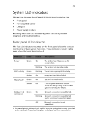
...standby mode. To purchase this option, contact your local Acer representative. Front panel LED indicators The five LED indicators mounted on the: • Front panel • Hot-plug HDD carrier • LAN port • Power supply module Knowing what each LED indicator signifies can aid in... normal mode. Indicator Color Status Description Power Green On The system has AC power and is powered on the mainboard.
...standby mode. To purchase this option, contact your local Acer representative. Front panel LED indicators The five LED indicators mounted on the: • Front panel • Hot-plug HDD carrier • LAN port • Power supply module Knowing what each LED indicator signifies can aid in... normal mode. Indicator Color Status Description Power Green On The system has AC power and is powered on the mainboard.
Altos G540 User's Guide EN
Page 33
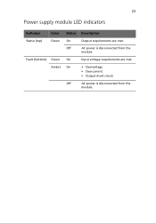
Fault (bottom) Green On Input voltage requirements are met. Amber On • Overvoltage • Overcurrent • Output short circuit Off AC power is disconnected from the module. 23 Power supply module LED indicators Indicator Color Status Description Status (top) Green On Output requirements are met. Off AC power is disconnected from the module.
Fault (bottom) Green On Input voltage requirements are met. Amber On • Overvoltage • Overcurrent • Output short circuit Off AC power is disconnected from the module. 23 Power supply module LED indicators Indicator Color Status Description Status (top) Green On Output requirements are met. Off AC power is disconnected from the module.
Altos G540 User's Guide EN
Page 57
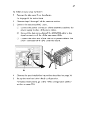
...for instructions. 2 Observe steps 2 through 5 of the previous section. 3 Connect the easy-swap HDD cables. (1) Connect the power connectors of the SAS/SATA2 cable to the power supply module HDD power cables. (2) Connect the data connectors of the SAS/SATA2 cable to the signal connectors of the of the easy-swap... HDDs. (3) Connect the other end of the SAS/SATA2 power cable to the "RAID configuration utilities" section on page...
...for instructions. 2 Observe steps 2 through 5 of the previous section. 3 Connect the easy-swap HDD cables. (1) Connect the power connectors of the SAS/SATA2 cable to the power supply module HDD power cables. (2) Connect the data connectors of the SAS/SATA2 cable to the signal connectors of the of the easy-swap... HDDs. (3) Connect the other end of the SAS/SATA2 power cable to the "RAID configuration utilities" section on page...
Altos G540 User's Guide EN
Page 76
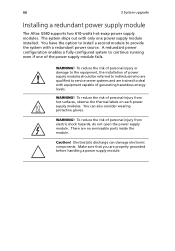
...power supply module The Altos G540 supports two 610-watts hot-swap power supply modules. A redundant power configuration enables a fully-configured system to continue running even if one power supply module installed. Electrostatic discharge can also consider wearing protective gloves. You can damage electronic components. WARNING! To reduce the risk of the power supply... WARNING! To reduce the risk of personal injury or damage to the equipment, the installation of power supply modules should be referred to individuals who are qualified to service server systems and are trained to ...
...power supply module The Altos G540 supports two 610-watts hot-swap power supply modules. A redundant power configuration enables a fully-configured system to continue running even if one power supply module installed. Electrostatic discharge can also consider wearing protective gloves. You can damage electronic components. WARNING! To reduce the risk of the power supply... WARNING! To reduce the risk of personal injury or damage to the equipment, the installation of power supply modules should be referred to individuals who are qualified to service server systems and are trained to ...
Altos G540 User's Guide EN
Page 77
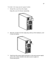
67 To install a hot-swap power supply module: 1 Detach the cover from the chassis. Keep the cover for future reassembly. 2 Slide the module into the empty bay until you feel resistance, and it locks into place. 3 Verify that the power status indicators on the main power supply and on the newly installed redundant power supply are illuminated green.
67 To install a hot-swap power supply module: 1 Detach the cover from the chassis. Keep the cover for future reassembly. 2 Slide the module into the empty bay until you feel resistance, and it locks into place. 3 Verify that the power status indicators on the main power supply and on the newly installed redundant power supply are illuminated green.
Altos G540 User's Guide EN
Page 113
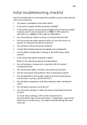
...a NEMA 5-15R outlet for 100-120 V or a NEMA 6-15R outlet for the problem you press the system power button to turn the server on (power on add-in boards sharing the same interrupt. 103 Initial troubleshooting checklist Use the checklist below to eliminate the possible cause... connected and secured? • Did you 're encountering. • AC power is available at the wall outlet? • Is the power supply module properly installed? • Is the system power cord properly plugged into the power supply module socket? Refer to the operating system documentation. • Are all hardware...
...a NEMA 5-15R outlet for 100-120 V or a NEMA 6-15R outlet for the problem you press the system power button to turn the server on (power on add-in boards sharing the same interrupt. 103 Initial troubleshooting checklist Use the checklist below to eliminate the possible cause... connected and secured? • Did you 're encountering. • AC power is available at the wall outlet? • Is the power supply module properly installed? • Is the system power cord properly plugged into the power supply module socket? Refer to the operating system documentation. • Are all hardware...
Altos G540 User's Guide EN
Page 114
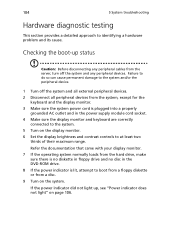
...make sure there is no diskette in floppy drive and no disc in the DVD-ROM drive. 8 If the power indicator is plugged into a properly grounded AC outlet and in the power supply module cord socket. 4 Make sure the display monitor and keyboard are correctly connected to the system. 5 Turn on... from the system, except for the keyboard and the display monitor. 3 Make sure the system power cord is lit, attempt to identifying a hardware problem and its cause. Checking the boot-up , see "Power indicator does not light" on the display monitor. 6 Set the display brightness and contrast controls ...
...make sure there is no diskette in floppy drive and no disc in the DVD-ROM drive. 8 If the power indicator is plugged into a properly grounded AC outlet and in the power supply module cord socket. 4 Make sure the display monitor and keyboard are correctly connected to the system. 5 Turn on... from the system, except for the keyboard and the display monitor. 3 Make sure the system power cord is lit, attempt to identifying a hardware problem and its cause. Checking the boot-up , see "Power indicator does not light" on the display monitor. 6 Set the display brightness and contrast controls ...
Altos G540 User's Guide EN
Page 116
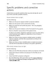
... and that the wall outlet has power. Test it by plugging another device. • Make sure the power indicator on the front panel is successful, install the cards back in cares and see if the system boots. Do the following : • Make sure the power supply module is properly installed. •... Make sure the power cord is set correctly. • Check that FDD is properly configured. • Run the BIOS setup utility and make ...
... and that the wall outlet has power. Test it by plugging another device. • Make sure the power indicator on the front panel is successful, install the cards back in cares and see if the system boots. Do the following : • Make sure the power supply module is properly installed. •... Make sure the power cord is set correctly. • Check that FDD is properly configured. • Run the BIOS setup utility and make ...
Altos G540 User's Guide EN
Page 144
... L LAN ports location 12 network connection indicator 22 network speed indicator 22 troubleshooting 108 LED indicators front panel 21 HDD carrier 22 LAN port 22 power supply module 23 LSI Logic Config Utility 116 LSI MegaRAID SAS RAID Configuration Utility 117 M mechanical specifications chassis 6 mainboard 6 media storage specification 4 upgrade option 7 memory BIOS...
... L LAN ports location 12 network connection indicator 22 network speed indicator 22 troubleshooting 108 LED indicators front panel 21 HDD carrier 22 LAN port 22 power supply module 23 LSI Logic Config Utility 116 LSI MegaRAID SAS RAID Configuration Utility 117 M mechanical specifications chassis 6 mainboard 6 media storage specification 4 upgrade option 7 memory BIOS...
Altos G540 User's Guide EN
Page 145
... 11 indicator, location 9 indicator, status 21 troubleshooting 106 turn off 33 turn on 29 power off via hardware 33 via software 33 power supply module fault indicator, description 23 fault indicator, location 12 install 66 redundant bay 13 release ...bridge 16 specification chipset 3 environmental 6 hardware monitoring 5 I/O ports 5 mechanical 6 media storage 4 memory 3 networking 4 operating system 5 PCI interface 4 power supply 5 processor 3 server management 5 system fan 5 video controller 4 status/fault indicator description 21 location 9 supervisor password 89 system boards ARMC/3 module 20...
... 11 indicator, location 9 indicator, status 21 troubleshooting 106 turn off 33 turn on 29 power off via hardware 33 via software 33 power supply module fault indicator, description 23 fault indicator, location 12 install 66 redundant bay 13 release ...bridge 16 specification chipset 3 environmental 6 hardware monitoring 5 I/O ports 5 mechanical 6 media storage 4 memory 3 networking 4 operating system 5 PCI interface 4 power supply 5 processor 3 server management 5 system fan 5 video controller 4 status/fault indicator description 21 location 9 supervisor password 89 system boards ARMC/3 module 20...
Altos G540 User's Guide EN
Page 146
... 37 expansion card 60 hard drive 41 installation precautions 37 memory 55 post-installation instructions 38 preinstallation instructions 38 processor 50 redundant power supply module 66 SAS controller board 62 T thermal grease 52 troubleshooting display problems 109 DVD-ROM drive problems 107 FAQ 106 FDD ...problem 106 hardware diagnostics 104 HDD problem 107 initial checklist 103 initial startup problems 102 memory problem 107 network problems 108 power indicator problem 106 software program problem 108 system reset 101 USB device problems 108 U UID switch 12 unit identification, see UID...
... 37 expansion card 60 hard drive 41 installation precautions 37 memory 55 post-installation instructions 38 preinstallation instructions 38 processor 50 redundant power supply module 66 SAS controller board 62 T thermal grease 52 troubleshooting display problems 109 DVD-ROM drive problems 107 FAQ 106 FDD ...problem 106 hardware diagnostics 104 HDD problem 107 initial checklist 103 initial startup problems 102 memory problem 107 network problems 108 power indicator problem 106 software program problem 108 system reset 101 USB device problems 108 U UID switch 12 unit identification, see UID...


