CE DoC
Page 1
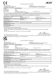
...:2019 EN301893 V2.1.1 Radio Equipment Model: AX211NGW,AX201NGW, Operation frequency and radio-frequency power are listed as below: [Bluetooth] 2402-2480MHz Viale delle Industrie 1/A, 20044 Arese (MI), Italy Tel: +39-02-939-921Fax: +39-02-9399-2913 Product: Personal Computer Trade Name: acer Model Number: D22W7 SKU Number: ConceptD CT500-53A********** CT500-53A********** (*... 2011/65/EU and ErP Directive 2009/125/EC. EC/EU DECLARATION OF CONFORMITY We, Acer Incorporated 8F, 88, Sec. 1, Xintai 5th Rd., Xizhi, New Taipei City 221, Taiwan Contact Person: Mr. RU Jan,e-mail:ru.jan...
...:2019 EN301893 V2.1.1 Radio Equipment Model: AX211NGW,AX201NGW, Operation frequency and radio-frequency power are listed as below: [Bluetooth] 2402-2480MHz Viale delle Industrie 1/A, 20044 Arese (MI), Italy Tel: +39-02-939-921Fax: +39-02-9399-2913 Product: Personal Computer Trade Name: acer Model Number: D22W7 SKU Number: ConceptD CT500-53A********** CT500-53A********** (*... 2011/65/EU and ErP Directive 2009/125/EC. EC/EU DECLARATION OF CONFORMITY We, Acer Incorporated 8F, 88, Sec. 1, Xintai 5th Rd., Xizhi, New Taipei City 221, Taiwan Contact Person: Mr. RU Jan,e-mail:ru.jan...

UK Conformity Assessed
Page 1
...Sec. 1, Xintai 5th Rd., Xizhi, New Taipei City 221, Taiwan Contact Person: Mr. RU Jan,e-mail:RU.Jan@acer.com Acer UK Ltd. Heathrow Blvd.III 282 Bath Rd. Drayton UB7 0DQ Tel: 0371-760-1005Fax: 0371-760-1005 Product: Personal Computer Trade Name: acer Model Number: D22W7 SKU Number: ConceptD CT500-53A********** CT500-53A********** (* is ... Products Regulations 2019 (EU) No.617/2013 EN301489-1 V2.2.3 BS EN61000-3-3:2013+A1:2019 EN301893 V2.1.1 Radio Equipment Model: AX211NGW,AX201NGW, Operation frequency and radio-frequency power are listed as below: [Bluetooth] 2402-2480MHz W.
...Sec. 1, Xintai 5th Rd., Xizhi, New Taipei City 221, Taiwan Contact Person: Mr. RU Jan,e-mail:RU.Jan@acer.com Acer UK Ltd. Heathrow Blvd.III 282 Bath Rd. Drayton UB7 0DQ Tel: 0371-760-1005Fax: 0371-760-1005 Product: Personal Computer Trade Name: acer Model Number: D22W7 SKU Number: ConceptD CT500-53A********** CT500-53A********** (* is ... Products Regulations 2019 (EU) No.617/2013 EN301489-1 V2.2.3 BS EN61000-3-3:2013+A1:2019 EN301893 V2.1.1 Radio Equipment Model: AX211NGW,AX201NGW, Operation frequency and radio-frequency power are listed as below: [Bluetooth] 2402-2480MHz W.
User Manual
Page 3
...-installation instructions ..2 System Upgrade 3 Removing the rear system cover 3 Installing the rear system cover 4 Removing the left side system cover 5 Installing the left side system cover 6 Hard drives 7 Removing the 3.5-inch hard drives 7 Installing the 3.5-inch hard drives 8 Memory 9 Memory configuration guidelines 9 Removing a memory module .10 Installing a memory module...11 Graphic board 12 Removing the Graphics board 12 Installing the Graphics board 14 M.2 SSD modules 16 Removing the M.2 SSD modules 16 Installing the M.2 SSD modules 19 CONCEPT D PALETTE 23 ConceptD...
...-installation instructions ..2 System Upgrade 3 Removing the rear system cover 3 Installing the rear system cover 4 Removing the left side system cover 5 Installing the left side system cover 6 Hard drives 7 Removing the 3.5-inch hard drives 7 Installing the 3.5-inch hard drives 8 Memory 9 Memory configuration guidelines 9 Removing a memory module .10 Installing a memory module...11 Graphic board 12 Removing the Graphics board 12 Installing the Graphics board 14 M.2 SSD modules 16 Removing the M.2 SSD modules 16 Installing the M.2 SSD modules 19 CONCEPT D PALETTE 23 ConceptD...

User Manual
Page 5
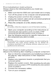
UPGRADING YOUR COMPUTER - 1 UPGRADING YOUR COMPUTER Installation precautions Before you install any procedure requiring ESD protection. Do not remove a component from its protective packaging until you are ready to a metal part of the computer before you install a computer component: 1. ESD precautions Electrostatic discharge (ESD) can damage your processor, disk drives, expansion boards, and other components. Required tools In performing the component replacement process...
UPGRADING YOUR COMPUTER - 1 UPGRADING YOUR COMPUTER Installation precautions Before you install any procedure requiring ESD protection. Do not remove a component from its protective packaging until you are ready to a metal part of the computer before you install a computer component: 1. ESD precautions Electrostatic discharge (ESD) can damage your processor, disk drives, expansion boards, and other components. Required tools In performing the component replacement process...
User Manual
Page 6
... and card reader slot is empty. 2. Unplug the network cable and all peripherals. 3. Place the computer on your computer according to the step-by- Make sure that the components are a qualified service technician. See installing the left side system cover on page 4. 4. Connect the necessary cables. 5. Open your computer. See to the computer and all connected peripheral devices from the computer. 4. UPGRADING YOUR COMPUTER Pre-installation instructions...
... and card reader slot is empty. 2. Unplug the network cable and all peripherals. 3. Place the computer on your computer according to the step-by- Make sure that the components are a qualified service technician. See installing the left side system cover on page 4. 4. Connect the necessary cables. 5. Open your computer. See to the computer and all connected peripheral devices from the computer. 4. UPGRADING YOUR COMPUTER Pre-installation instructions...

User Manual
Page 7
System Upgrade UPGRADING YOUR COMPUTER - 3 Removing the rear system cover 1. Set the cover aside for re-installation later. Remove the screw that you proceed, make sure that secure the rear system cover to it. Read the Pre-installation instructions on page 2. 2. Take off your computer and all peripherals connected to the computer. 3. Before you have turned off the rear system cover. 4.
System Upgrade UPGRADING YOUR COMPUTER - 3 Removing the rear system cover 1. Set the cover aside for re-installation later. Remove the screw that you proceed, make sure that secure the rear system cover to it. Read the Pre-installation instructions on page 2. 2. Take off your computer and all peripherals connected to the computer. 3. Before you have turned off the rear system cover. 4.

User Manual
Page 11
Removing the 3.5-inch hard drives 1. Pull both sides of two 3.5-inch SATA hard drives in the internal HDD cage. UPGRADING YOUR COMPUTER - 7 Hard drives The computer supports installation of the HDD carrier (1) then remove the hard drive (2). Pull and remove the hard drives from the chassis. 3. Perform the Pre-installation instructions on page 2. 2.
Removing the 3.5-inch hard drives 1. Pull both sides of two 3.5-inch SATA hard drives in the internal HDD cage. UPGRADING YOUR COMPUTER - 7 Hard drives The computer supports installation of the HDD carrier (1) then remove the hard drive (2). Pull and remove the hard drives from the chassis. 3. Perform the Pre-installation instructions on page 2. 2.

User Manual
Page 12
UPGRADING YOUR COMPUTER Installing the 3.5-inch hard drives 1. Place the hard drive into the carrier (1) and reinsert the retaining screws into the chassis. 4. Insert the hard drives into the hard drive (2). 3. Observe the Post-installation instructions on page 2. Remove the new hard drives from their packaging. 2. 8 -
UPGRADING YOUR COMPUTER Installing the 3.5-inch hard drives 1. Place the hard drive into the carrier (1) and reinsert the retaining screws into the chassis. 4. Insert the hard drives into the hard drive (2). 3. Observe the Post-installation instructions on page 2. Remove the new hard drives from their packaging. 2. 8 -

User Manual
Page 15
UPGRADING YOUR COMPUTER - 11 Installing a memory module Note DIMM slots on the mainboard must be inserted in the memory slot. 5. Remove the new memory module from its packaging, handling it can only be installed only in DIMM1 slot followed by the edges. 3. See Installing the graphics board on page 2. Replace the graphics board. Be sure to the slot until the retaining clips snap inward (2). The module is keyed so it...
UPGRADING YOUR COMPUTER - 11 Installing a memory module Note DIMM slots on the mainboard must be inserted in the memory slot. 5. Remove the new memory module from its packaging, handling it can only be installed only in DIMM1 slot followed by the edges. 3. See Installing the graphics board on page 2. Replace the graphics board. Be sure to the slot until the retaining clips snap inward (2). The module is keyed so it...
User Manual
Page 16
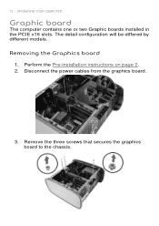
Perform the Pre-installation instructions on page 2. 2. Disconnect the power cables from the graphics board. 3. UPGRADING YOUR COMPUTER Graphic board The computer contains one or two Graphic boards installed in the PCIE x16 slots. The detail configuration will be differed by different models. Remove the three screws that secures the graphics board to the chassis. Removing the Graphics board 1. 12 -
Perform the Pre-installation instructions on page 2. 2. Disconnect the power cables from the graphics board. 3. UPGRADING YOUR COMPUTER Graphic board The computer contains one or two Graphic boards installed in the PCIE x16 slots. The detail configuration will be differed by different models. Remove the three screws that secures the graphics board to the chassis. Removing the Graphics board 1. 12 -

User Manual
Page 18
Press the metal clip to make sure the graphic board and power supply could work. 3. Note For replace/upgrade graphic board, please check the specification of graphic board & power supply first in order to secure the graphics board bracket. UPGRADING YOUR COMPUTER Installing the Graphics board 1. Insert the graphics boards into the PCIE x16 slot and press it down until it latches into place. 14 - Remove the new graphics board from its packaging. 2.
Press the metal clip to make sure the graphic board and power supply could work. 3. Note For replace/upgrade graphic board, please check the specification of graphic board & power supply first in order to secure the graphics board bracket. UPGRADING YOUR COMPUTER Installing the Graphics board 1. Insert the graphics boards into the PCIE x16 slot and press it down until it latches into place. 14 - Remove the new graphics board from its packaging. 2.
User Manual
Page 27
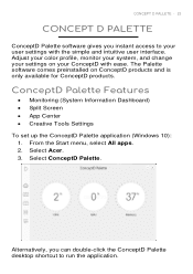
... user interface. ConceptD Palette Features Monitoring (System Information Dashboard) Split Screen App Center Creative Tools Settings To set up the ConceptD Palette application (Windows 10): 1. Alternatively, you instant access to run the application. From the Start menu, select All apps. 2. Adjust your color profile, monitor your system, and change your user settings with ease. Select Acer. 3. Select ConceptD Palette. CONCEPT D PALLETE - 23 CONCEPT D PALETTE ConceptD Palette software...
... user interface. ConceptD Palette Features Monitoring (System Information Dashboard) Split Screen App Center Creative Tools Settings To set up the ConceptD Palette application (Windows 10): 1. Alternatively, you instant access to run the application. From the Start menu, select All apps. 2. Adjust your color profile, monitor your system, and change your user settings with ease. Select Acer. 3. Select ConceptD Palette. CONCEPT D PALLETE - 23 CONCEPT D PALETTE ConceptD Palette software...
Safety Guide
Page 6
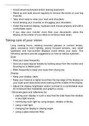
... tensing your muscles or shrugging your shoulders. • Install the external display, keyboard and mouse properly and within comfortable reach. • If you view your monitor more than the top edge of your eyes from the monitor and focusing on a distant point. • Blink frequently to a comfortable level for comfortable use • Avoid slouching forward and/or leaning backward...
... tensing your muscles or shrugging your shoulders. • Install the external display, keyboard and mouse properly and within comfortable reach. • If you view your monitor more than the top edge of your eyes from the monitor and focusing on a distant point. • Blink frequently to a comfortable level for comfortable use • Avoid slouching forward and/or leaning backward...

Safety Guide
Page 10
... ventilation openings and AC adapter may contain small parts. Do not pack your computer carefully Use a quality carrying case that could be blocked or covered. Pack your computer in contact with exposed skin can cause discomfort or burns. These openings must not be seriously damaged. • Slots and openings are provided for using your skin or body. • Your device and...
... ventilation openings and AC adapter may contain small parts. Do not pack your computer carefully Use a quality carrying case that could be blocked or covered. Pack your computer in contact with exposed skin can cause discomfort or burns. These openings must not be seriously damaged. • Slots and openings are provided for using your skin or body. • Your device and...
Safety Guide
Page 12
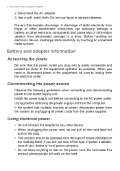
... other electronic components and cause loss of power indicated on the cord. Disconnecting the power source Observe the following guidelines when connecting and disconnecting power to the power supply unit: Install the power supply unit before removing the power supply unit from electrostatic damage to the equipment operator as possible. If you plug into is easily accessible and located as close to a drive. 12 - Use a soft, moist cloth.
... other electronic components and cause loss of power indicated on the cord. Disconnecting the power source Observe the following guidelines when connecting and disconnecting power to the power supply unit: Install the power supply unit before removing the power supply unit from electrostatic damage to the equipment operator as possible. If you plug into is easily accessible and located as close to a drive. 12 - Use a soft, moist cloth.
Safety Guide
Page 15
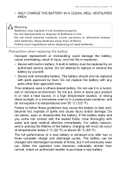
... fluids, rinse thoroughly with parts approved by yourself. • Device with removable battery: The battery should only be charged and discharged hundreds of a new battery is achieved only after two or three complete charge and discharge cycles. Do not use it in a humid, wet or corrosive environment. Warning Batteries may cause the battery to replace or remove the battery by Acer. Do not attempt...
... fluids, rinse thoroughly with parts approved by yourself. • Device with removable battery: The battery should only be charged and discharged hundreds of a new battery is achieved only after two or three complete charge and discharge cycles. Do not use it in a humid, wet or corrosive environment. Warning Batteries may cause the battery to replace or remove the battery by Acer. Do not attempt...
Safety Guide
Page 19
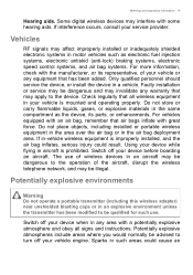
... operate a portable transmitter (including this wireless adapter) near unshielded blasting caps or in such areas could result. The use . Check regularly that may be qualified for such use of wireless devices in -vehicle wireless equipment is improperly installed, and the air bag inflates, serious injury could cause an If in an aircraft may be advised to the device. Switch off your service...
... operate a portable transmitter (including this wireless adapter) near unshielded blasting caps or in such areas could result. The use . Check regularly that may be qualified for such use of wireless devices in -vehicle wireless equipment is improperly installed, and the air bag inflates, serious injury could cause an If in an aircraft may be advised to the device. Switch off your service...
Safety Guide
Page 22
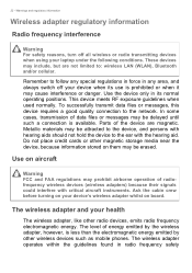
..., and always switch off all wireless or radio transmitting devices when using your device when its normal operating positions. The wireless adapter operates within the guidelines found in radio frequency safety This device meets RF exposure guidelines when used normally. Use on your health The wireless adapter, like other magnetic storage media near the device, because information stored on board. Metallic materials may prohibit airborne operation of data...
..., and always switch off all wireless or radio transmitting devices when using your device when its normal operating positions. The wireless adapter operates within the guidelines found in radio frequency safety This device meets RF exposure guidelines when used normally. Use on your health The wireless adapter, like other magnetic storage media near the device, because information stored on board. Metallic materials may prohibit airborne operation of data...
Safety Guide
Page 24
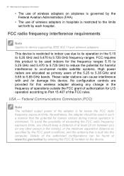
...; The use of the adapter is minimized. FCC radio frequency interference requirements Note Applies to the limits set forth by entering the FCC ID number on airplanes is restricted to device supporting IEEE 802.11a/ac wireless adapters. Federal Communications Commission (FCC) Note The radiated output power of wireless adapters on the device. Nevertheless, the adapter should keep a distance of the authorized configurations can cause...
...; The use of the adapter is minimized. FCC radio frequency interference requirements Note Applies to the limits set forth by entering the FCC ID number on airplanes is restricted to device supporting IEEE 802.11a/ac wireless adapters. Federal Communications Commission (FCC) Note The radiated output power of wireless adapters on the device. Nevertheless, the adapter should keep a distance of the authorized configurations can cause...
Safety Guide
Page 25
..., that to operate the equipment. Operation of the equipment experiencing the interference. • Increase the distance between the wireless adapter and the equipment experiencing the interference. • Connect the computer with the instructions, the wireless adapter may cause undesired operation. • 15.21 You are designed to Part 15 of the FCC Rules. If the wireless adapter is not installed and used in a residential...
..., that to operate the equipment. Operation of the equipment experiencing the interference. • Increase the distance between the wireless adapter and the equipment experiencing the interference. • Connect the computer with the instructions, the wireless adapter may cause undesired operation. • 15.21 You are designed to Part 15 of the FCC Rules. If the wireless adapter is not installed and used in a residential...


