Aspire X1700 / Veriton X270 Service Guide
Page 7
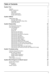
... Entering CMOS setup 8 Navigating Through the Setup Utility 8 Setup Utility Menus 9 System Disassembly 23 Pre-disassembly Procedure 24 Main Unit Disassembly 25 X1700 model 25 X270 model 26 Screw List 27 Removing the Side Panel 28 Removing the Front Bezel 29 Removing the Heat Sink Fan Assembly 30... Removing the Processor 32 Removing the Optical Drive 34 Removing the Hard Disk Drive 37 Removing the Power Supply 40 Removing the Memory Modules 42 ...
... Entering CMOS setup 8 Navigating Through the Setup Utility 8 Setup Utility Menus 9 System Disassembly 23 Pre-disassembly Procedure 24 Main Unit Disassembly 25 X1700 model 25 X270 model 26 Screw List 27 Removing the Side Panel 28 Removing the Front Bezel 29 Removing the Heat Sink Fan Assembly 30... Removing the Processor 32 Removing the Optical Drive 34 Removing the Hard Disk Drive 37 Removing the Power Supply 40 Removing the Memory Modules 42 ...
Aspire X1700 / Veriton X270 Service Guide
Page 9
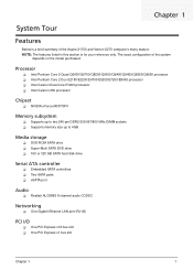
...of the system depends on the model purchased. The exact configuration of the Aspire X1700 and Veriton X270 computer's many feature: NOTE: The features listed in this section is for your reference only. Processor Intel Pentium Core 2 Quad Q6600/Q6700/Q8200/Q9300/Q9400/Q9450/...Q9550/Q9650 processor Intel Pentium Core 2 Duo E2180/E2200/E4700/E5200/E7200/E8400 processor Intel Celeron Dual-Core E1200 processor Intel Celeron 450 processor Chipset NVIDIA nForce MCP73PV Memory subsystem Supports up...
...of the system depends on the model purchased. The exact configuration of the Aspire X1700 and Veriton X270 computer's many feature: NOTE: The features listed in this section is for your reference only. Processor Intel Pentium Core 2 Quad Q6600/Q6700/Q8200/Q9300/Q9400/Q9450/...Q9550/Q9650 processor Intel Pentium Core 2 Duo E2180/E2200/E4700/E5200/E7200/E8400 processor Intel Celeron Dual-Core E1200 processor Intel Celeron 450 processor Chipset NVIDIA nForce MCP73PV Memory subsystem Supports up...

Aspire X1700 / Veriton X270 Service Guide
Page 18
... of the system. Product Information The Product Information menu displays basic information about the system. Version number of CPU installed on the system. Parameter Processor Type Processor Speed System Memory System Manufacturer Product Name System Serial Number System BIOS Version BIOS Release Date Asset Tag Number Description Type of the BIOS setup...
... of the system. Product Information The Product Information menu displays basic information about the system. Version number of CPU installed on the system. Parameter Processor Type Processor Speed System Memory System Manufacturer Product Name System Serial Number System BIOS Version BIOS Release Date Asset Tag Number Description Type of the BIOS setup...

Aspire X1700 / Veriton X270 Service Guide
Page 21
Enables or disables remapping of overlapped PCI memory above the total physical memory. When enabled, the processor disables code execution when a worm attempts to change the setting. Note: A full reset is required to insert a code in the buffer ...display support. Option Enabled Disabled Enabled Disabled Enabled Disabled Enabled Disabled Disabled Enabled Auto PCIE Onboard VGA Chapter 2 13 When disabled, the processor forces the Execute Disable (XD) Bit feature flag to always return to reduce power consumption. Enables or disables the Virtualization Technology (VT) availability.
Enables or disables remapping of overlapped PCI memory above the total physical memory. When enabled, the processor disables code execution when a worm attempts to change the setting. Note: A full reset is required to insert a code in the buffer ...display support. Option Enabled Disabled Enabled Disabled Enabled Disabled Enabled Disabled Disabled Enabled Auto PCIE Onboard VGA Chapter 2 13 When disabled, the processor forces the Execute Disable (XD) Bit feature flag to always return to reduce power consumption. Enables or disables the Virtualization Technology (VT) availability.

Aspire X1700 / Veriton X270 Service Guide
Page 25
Option Enabled Disabled Chapter 2 17 Note: Remember to lock up. Frequency/Voltage Control Parameter Spread Spectrum Description Enables or disables the reduction of the mainboard's EMI. A slight jitter can introduce a temporary boost in clock speed causing the overclocked processor to disable the Spread Spectrum feature if you are overclocking.
Option Enabled Disabled Chapter 2 17 Note: Remember to lock up. Frequency/Voltage Control Parameter Spread Spectrum Description Enables or disables the reduction of the mainboard's EMI. A slight jitter can introduce a temporary boost in clock speed causing the overclocked processor to disable the Spread Spectrum feature if you are overclocking.
Aspire X1700 / Veriton X270 Service Guide
Page 39
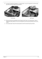
Lay down in an upright position, on the heat sink fan assembly touch the work surface. 7. Remove the heat sink fan assembly from the chassis then lay it down the heat sink fan assembly, in an upright position-with the thermal patch facing upward. Use an alcohol pad to wipe off the thermal grease from the mainboard. X1700 model X270 model 6. 5. Chapter 3 31 Do not let the thermal patch on top of the optical drive, as shown below, then disconnect the fan cable from both the heat sink and the processor.
Lay down in an upright position, on the heat sink fan assembly touch the work surface. 7. Remove the heat sink fan assembly from the chassis then lay it down the heat sink fan assembly, in an upright position-with the thermal patch facing upward. Use an alcohol pad to wipe off the thermal grease from the mainboard. X1700 model X270 model 6. 5. Chapter 3 31 Do not let the thermal patch on top of the optical drive, as shown below, then disconnect the fan cable from both the heat sink and the processor.

Aspire X1700 / Veriton X270 Service Guide
Page 40
Pull the load lever to create a backup file of all important data. Removing the Processor IMPORTANT:Before removing a processor from the mainboard, make sure to the fully open, upright position (2) and lift the load plate (3). 32 Chapter 3 See "Removing the Heat Sink Fan Assembly" on page 29. 3. See "Removing the Front Bezel" on page 30. 4. See "Removing the Side Panel" on . WARNING:The processor becomes very hot when the system is on page 28. 2. Release the load lever (1). 5. Allow it to cool off first before handling. 1.
Pull the load lever to create a backup file of all important data. Removing the Processor IMPORTANT:Before removing a processor from the mainboard, make sure to the fully open, upright position (2) and lift the load plate (3). 32 Chapter 3 See "Removing the Heat Sink Fan Assembly" on page 29. 3. See "Removing the Front Bezel" on page 30. 4. See "Removing the Side Panel" on . WARNING:The processor becomes very hot when the system is on page 28. 2. Release the load lever (1). 5. Allow it to cool off first before handling. 1.

Aspire X1700 / Veriton X270 Service Guide
Page 41
Chapter 3 33 IMPORTANT:If you are going to install a new processor, note the arrow on the corner to make sure the processor is properly oriented over the socket. Pull out the processor from the socket. 6.
Chapter 3 33 IMPORTANT:If you are going to install a new processor, note the arrow on the corner to make sure the processor is properly oriented over the socket. Pull out the processor from the socket. 6.
Aspire X1700 / Veriton X270 Service Guide
Page 42
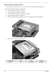
...'s optical drive: 1. Screw (Quantity) M3xL5 (1) Color Black Torque 5.5 to remove the X1700 and X270 computers' optical drive. See "Removing the Front Bezel" on page 32. 5. See "Removing the Processor" on page 29. 3. Remove the screw (B) from the rear of the optical drive and the mainboard. 6. See "Removing the Heat Sink Fan Assembly...
...'s optical drive: 1. Screw (Quantity) M3xL5 (1) Color Black Torque 5.5 to remove the X1700 and X270 computers' optical drive. See "Removing the Front Bezel" on page 32. 5. See "Removing the Processor" on page 29. 3. Remove the screw (B) from the rear of the optical drive and the mainboard. 6. See "Removing the Heat Sink Fan Assembly...

Aspire X1700 / Veriton X270 Service Guide
Page 43
See "Removing the Front Bezel" on page 32. 5. Disconnect the data and power cables from the rear of the drive bay. Pull the drive out of the optical drive and the mainboard. 7. To remove the X270 computer's optical drive: 1. See "Removing the Processor" on page 29. 3. See "Removing the Side Panel" on page 30. 4. Chapter 3 35 See "Removing the Heat Sink Fan Assembly" on page 28. 2.
See "Removing the Front Bezel" on page 32. 5. Disconnect the data and power cables from the rear of the drive bay. Pull the drive out of the optical drive and the mainboard. 7. To remove the X270 computer's optical drive: 1. See "Removing the Processor" on page 29. 3. See "Removing the Side Panel" on page 30. 4. Chapter 3 35 See "Removing the Heat Sink Fan Assembly" on page 28. 2.
Aspire X1700 / Veriton X270 Service Guide
Page 45
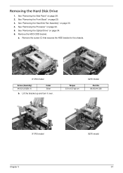
Removing the Hard Disk Drive 1. See "Removing the Front Bezel" on page 30. 4. a. Lift the bracket up and turn it over. See "Removing the Heat Sink Fan Assembly" on page 29. 3. See "Removing the Side Panel" on page 32. 5. Remove the HDD-ODD bracket. X1700 model Screw (Quantity) #6-32 L6 BZN (1) Color Silver b. See "Removing the Processor" on page 28. 2. See "Removing the Optical Drive" on page 34. 6. Remove the screw (C) that secures the HDD bracket to 6.5 kgf-cm X270 model Part No. 86.00J44.C60 X1700 model Chapter 3 X270 model 37 Torque 5.5 to the chassis.
Removing the Hard Disk Drive 1. See "Removing the Front Bezel" on page 30. 4. a. Lift the bracket up and turn it over. See "Removing the Heat Sink Fan Assembly" on page 29. 3. See "Removing the Side Panel" on page 32. 5. Remove the HDD-ODD bracket. X1700 model Screw (Quantity) #6-32 L6 BZN (1) Color Silver b. See "Removing the Processor" on page 28. 2. See "Removing the Optical Drive" on page 34. 6. Remove the screw (C) that secures the HDD bracket to 6.5 kgf-cm X270 model Part No. 86.00J44.C60 X1700 model Chapter 3 X270 model 37 Torque 5.5 to the chassis.
Aspire X1700 / Veriton X270 Service Guide
Page 48
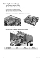
See "Removing the Processor" on page 28. 2. Disconnect the 4-pin and 24-pin power supply cables from the mainboard. Remove the screw (C) that secures the power supply to 6.3 kgf-... "Removing the Heat Sink Fan Assembly" on page 37. 7. See "Removing the Front Bezel" on page 34. 6. See "Removing the Optical Drive" on page 29. 3. X1700 model 8. X270 model Screw (Quantity) #6-32 L6 BZN (1) Color Silver Torque 5.7 to the chassis.
See "Removing the Processor" on page 28. 2. Disconnect the 4-pin and 24-pin power supply cables from the mainboard. Remove the screw (C) that secures the power supply to 6.3 kgf-... "Removing the Heat Sink Fan Assembly" on page 37. 7. See "Removing the Front Bezel" on page 34. 6. See "Removing the Optical Drive" on page 29. 3. X1700 model 8. X270 model Screw (Quantity) #6-32 L6 BZN (1) Color Silver Torque 5.7 to the chassis.

Aspire X1700 / Veriton X270 Service Guide
Page 50
See "Removing the Optical Drive" on page 30. 4. X1700 model X270 model 42 Chapter 3 See "Removing the Heat Sink Fan Assembly" on page 34. 6. See "Removing the Front Bezel" on page 28. 2. Gently pull ... upward to create a backup file of the DIMM slot outward to release the DIMM (1). 8. See "Removing the Side Panel" on page 29. 3. See "Removing the Processor" on page 37. 7. See "Removing the Hard Disk Drive" on page 32. 5. Removing the Memory Modules IMPORTANT:Before removing any DIMM from the memory board...
See "Removing the Optical Drive" on page 30. 4. X1700 model X270 model 42 Chapter 3 See "Removing the Heat Sink Fan Assembly" on page 34. 6. See "Removing the Front Bezel" on page 28. 2. Gently pull ... upward to create a backup file of the DIMM slot outward to release the DIMM (1). 8. See "Removing the Side Panel" on page 29. 3. See "Removing the Processor" on page 37. 7. See "Removing the Hard Disk Drive" on page 32. 5. Removing the Memory Modules IMPORTANT:Before removing any DIMM from the memory board...

Aspire X1700 / Veriton X270 Service Guide
Page 51
See "Removing the Hard Disk Drive" on page 30. 4. See "Removing the Heat Sink Fan Assembly" on page 37. 7. Part No. 86.9A5G6.162 Chapter 3 43 See "Removing the Optical Drive" on page 32. 5. Gently pull the card to the chassis. Removing the VGA Card (X1700 model) 1. See "Removing the Processor" on page 34. 6. See "Removing the Front Bezel" on page 28. 2. Remove the screw (E) that secures the card to remove it from the mainboard. Screw (Quantity) #6-32 5MM NI (1) Color Silver Torque 5.5 to 6.5 kgf-cm 8. See "Removing the Side Panel" on page 29. 3.
See "Removing the Hard Disk Drive" on page 30. 4. See "Removing the Heat Sink Fan Assembly" on page 37. 7. Part No. 86.9A5G6.162 Chapter 3 43 See "Removing the Optical Drive" on page 32. 5. Gently pull the card to the chassis. Removing the VGA Card (X1700 model) 1. See "Removing the Processor" on page 34. 6. See "Removing the Front Bezel" on page 28. 2. Remove the screw (E) that secures the card to remove it from the mainboard. Screw (Quantity) #6-32 5MM NI (1) Color Silver Torque 5.5 to 6.5 kgf-cm 8. See "Removing the Side Panel" on page 29. 3.

Aspire X1700 / Veriton X270 Service Guide
Page 52
See "Removing the Optical Drive" on page 28. 2. See "Removing the Side Panel" on page 34. 6. Gently pull the card to the chassis. See "Removing the Heat Sink Fan Assembly" on page 29. 3. Remove the screw (E) that secures the card to remove it from the mainboard. Screw (Quantity) #6-32 5MM NI (1) Color Silver Torque 5.5 to 6.5 kgf-cm 8. Part No. 86.9A5G6.162 44 Chapter 3 See "Removing the Front Bezel" on page 30. 4. See "Removing the Processor" on page 37. 7. See "Removing the Hard Disk Drive" on page 32. 5. Removing the TV Tuner Card (X1700 model) 1.
See "Removing the Optical Drive" on page 28. 2. See "Removing the Side Panel" on page 34. 6. Gently pull the card to the chassis. See "Removing the Heat Sink Fan Assembly" on page 29. 3. Remove the screw (E) that secures the card to remove it from the mainboard. Screw (Quantity) #6-32 5MM NI (1) Color Silver Torque 5.5 to 6.5 kgf-cm 8. Part No. 86.9A5G6.162 44 Chapter 3 See "Removing the Front Bezel" on page 30. 4. See "Removing the Processor" on page 37. 7. See "Removing the Hard Disk Drive" on page 32. 5. Removing the TV Tuner Card (X1700 model) 1.

Aspire X1700 / Veriton X270 Service Guide
Page 53
See "Removing the Processor" on page 42. 8. See "Removing the Memory Modules" on page 32. 5. Disconnect one end of the USB, 1394, and audio cables from the I /O and Card Reader Boards 1. Removing the Front I /O and card reader boards. X1700 model 9. See "Removing the Heat Sink Fan Assembly" on page 28. 2. X270 model Chapter 3 45 See "Removing the Side Panel" on page 30. 4. See "Removing the Front Bezel" on page 34. 6. See "Removing the Optical Drive" on page 29. 3. See "Removing the Hard Disk Drive" on page 37. 7. Open the cable retention clip.
See "Removing the Processor" on page 42. 8. See "Removing the Memory Modules" on page 32. 5. Disconnect one end of the USB, 1394, and audio cables from the I /O and Card Reader Boards 1. Removing the Front I /O and card reader boards. X1700 model 9. See "Removing the Heat Sink Fan Assembly" on page 28. 2. X270 model Chapter 3 45 See "Removing the Side Panel" on page 30. 4. See "Removing the Front Bezel" on page 34. 6. See "Removing the Optical Drive" on page 29. 3. See "Removing the Hard Disk Drive" on page 37. 7. Open the cable retention clip.

Aspire X1700 / Veriton X270 Service Guide
Page 57
See "Removing the Processor" on page 45. 11. See "Removing the Front I/O and Card Reader Boards" on page 32. 5. Screw (Quantity) M3xL5 (1) Color Black Torque 5.5 to 6.5 kgf-cm Part .... 12. Removing the Mainboard 1. See "Removing the Side Panel" on page 29. 3. See "Removing the Memory Modules" on page 43. 9. See "Removing the VGA Card (X1700 model)" on page 42. 8. Remove the screw (B) on page 30. 4. See "Removing the Heat Sink Fan Assembly" on the rear panel. See "Removing the Hard...
See "Removing the Processor" on page 45. 11. See "Removing the Front I/O and Card Reader Boards" on page 32. 5. Screw (Quantity) M3xL5 (1) Color Black Torque 5.5 to 6.5 kgf-cm Part .... 12. Removing the Mainboard 1. See "Removing the Side Panel" on page 29. 3. See "Removing the Memory Modules" on page 43. 9. See "Removing the VGA Card (X1700 model)" on page 42. 8. Remove the screw (B) on page 30. 4. See "Removing the Heat Sink Fan Assembly" on the rear panel. See "Removing the Hard...
Aspire X1700 / Veriton X270 Service Guide
Page 59
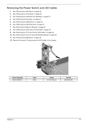
... Torque 5.7 to the chassis. Removing the Power Switch and LED Cables 1. See "Removing the TV Tuner Card (X1700 model)" on page 49. 12. See "Removing the Processor" on page 43. 9. See "Removing the VGA Card (X1700 model)" on page 32. 5. Remove the screw (C) that secures the LED bracket to 6.3 kgf-cm Part No...
... Torque 5.7 to the chassis. Removing the Power Switch and LED Cables 1. See "Removing the TV Tuner Card (X1700 model)" on page 49. 12. See "Removing the Processor" on page 43. 9. See "Removing the VGA Card (X1700 model)" on page 32. 5. Remove the screw (C) that secures the LED bracket to 6.3 kgf-cm Part No...
Aspire X1700 / Veriton X270 Service Guide
Page 62
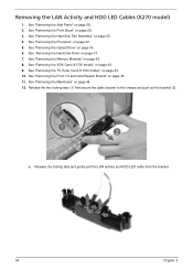
... Assembly" on page 28. 2. See "Removing the Memory Modules" on page 43. 9. See "Removing the VGA Card (X1700 model)" on page 42. 8. See "Removing the Mainboard" on page 32. 5. c. See "Removing the Processor" on page 49. 12. See "Removing the Hard Disk Drive" on page 34. 6. Removing the LAN Activity and... the Front Bezel" on page 45. 11. See "Removing the Front I/O and Card Reader Boards" on page 29. 3. See "Removing the TV Tuner Card (X1700 model)" on page 44. 10. Release the locking tabs and gently pull the LAN activity and HDD LED cable from the bracket. 54 Chapter 3
... Assembly" on page 28. 2. See "Removing the Memory Modules" on page 43. 9. See "Removing the VGA Card (X1700 model)" on page 42. 8. See "Removing the Mainboard" on page 32. 5. c. See "Removing the Processor" on page 49. 12. See "Removing the Hard Disk Drive" on page 34. 6. Removing the LAN Activity and... the Front Bezel" on page 45. 11. See "Removing the Front I/O and Card Reader Boards" on page 29. 3. See "Removing the TV Tuner Card (X1700 model)" on page 44. 10. Release the locking tabs and gently pull the LAN activity and HDD LED cable from the bracket. 54 Chapter 3
Aspire X1700 / Veriton X270 Service Guide
Page 69
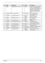
... Bottom: VGA Port 16 HDMI HDMI port 17 PSKBM1 Top: PS2 Mouse Port Bottom: PS2 Keyboard Port 18 ATX12V1 4-pin ATX power connector 19 CPU1 Processor socket 20 CPU_FAN Processor fan cable connector 21 DIMM1 and 2 System memory slots 22 GPIO33 GPIO32 General Purpose Input and Output jumper Chapter 5 61
... Bottom: VGA Port 16 HDMI HDMI port 17 PSKBM1 Top: PS2 Mouse Port Bottom: PS2 Keyboard Port 18 ATX12V1 4-pin ATX power connector 19 CPU1 Processor socket 20 CPU_FAN Processor fan cable connector 21 DIMM1 and 2 System memory slots 22 GPIO33 GPIO32 General Purpose Input and Output jumper Chapter 5 61


