
Acer V5-471 Notebook Service Guide
Page 5
... Dimensions and Weight 1-10 Environment 1-10 Notebook Tour 1-11 Open Front View 1-11 Close Front View 1-12 Left View 1-13 Right View 1-14 Base View 1-15 Touchpad Basics 1-16 Keyboard 1-17 D2D Recovery 1-21 System Block Diagram 1-22 Specification Tables 1-23 CHAPTER 2 System Utilities BIOS Setup Utility 2-3 Navigating the BIOS Utility...
... Dimensions and Weight 1-10 Environment 1-10 Notebook Tour 1-11 Open Front View 1-11 Close Front View 1-12 Left View 1-13 Right View 1-14 Base View 1-15 Touchpad Basics 1-16 Keyboard 1-17 D2D Recovery 1-21 System Block Diagram 1-22 Specification Tables 1-23 CHAPTER 2 System Utilities BIOS Setup Utility 2-3 Navigating the BIOS Utility...
Acer V5-471 Notebook Service Guide
Page 6
Exit 2-12 BIOS Flash Utilities 2-13 DOS Flash Utility 2-14 WinFlash Utility 2-14 Remove HDD/BIOS Password Utilities 2-15 Removing the HDD Password 2-15 Removing the BIOS Passwords 2-16 Clearing the BIOS Passwords 2-17 Using DMI Tools 2-18 LAN EEPROM Utility 2-18 CHAPTER 3 ...Removing the Battery Pack 3-9 Removing the DIMM Cover 3-10 Removing the DIMM Modules 3-11 Removing the ODD Module 3-12 Removing the Keyboard 3-15 Main Unit Disassembly Process 3-17 Main Unit Disassembly Flowchart 3-17 Removing the Palmrest Module/Upper Case 3-18 Removing the Touchpad Board 3-21 Removing...
Exit 2-12 BIOS Flash Utilities 2-13 DOS Flash Utility 2-14 WinFlash Utility 2-14 Remove HDD/BIOS Password Utilities 2-15 Removing the HDD Password 2-15 Removing the BIOS Passwords 2-16 Clearing the BIOS Passwords 2-17 Using DMI Tools 2-18 LAN EEPROM Utility 2-18 CHAPTER 3 ...Removing the Battery Pack 3-9 Removing the DIMM Cover 3-10 Removing the DIMM Modules 3-11 Removing the ODD Module 3-12 Removing the Keyboard 3-15 Main Unit Disassembly Process 3-17 Main Unit Disassembly Flowchart 3-17 Removing the Palmrest Module/Upper Case 3-18 Removing the Touchpad Board 3-21 Removing...
Acer V5-471 Notebook Service Guide
Page 8
...Failure 4-7 Keyboard Failure 4-8 Touchpad Failure 4-9 Internal Speaker Failure 4-10 Microphone Failure 4-12 USB Failure 4-13 WLAN Failure 4-14 Bluetooth Failure 4-15 Card Reader Failure 4-16 Thermal Unit Failure 4-17 Other Functions Failure 4-18 Intermittent Problems 4-19 Undetermined Problems 4-19 Error Codes 4-20 BIOS Beep...Locations Mainboard Layout 5-3 Clearing Password Check and BIOS Recovery 5-7 Clearing the BIOS Passwords 5-7 Performing a BIOS Recovery 5-8 CHAPTER 6 FRU List Aspire MS2360 6-4 Exploded Diagrams 6-4 Main Assembly 6-4 LCD Assembly 6-6 FRU List 6-7 viii
...Failure 4-7 Keyboard Failure 4-8 Touchpad Failure 4-9 Internal Speaker Failure 4-10 Microphone Failure 4-12 USB Failure 4-13 WLAN Failure 4-14 Bluetooth Failure 4-15 Card Reader Failure 4-16 Thermal Unit Failure 4-17 Other Functions Failure 4-18 Intermittent Problems 4-19 Undetermined Problems 4-19 Error Codes 4-20 BIOS Beep...Locations Mainboard Layout 5-3 Clearing Password Check and BIOS Recovery 5-7 Clearing the BIOS Passwords 5-7 Performing a BIOS Recovery 5-8 CHAPTER 6 FRU List Aspire MS2360 6-4 Exploded Diagrams 6-4 Main Assembly 6-4 LCD Assembly 6-6 FRU List 6-7 viii
Acer V5-471 Notebook Service Guide
Page 12
... Dimensions and Weight 1-10 Environment 1-10 Notebook Tour 1-11 Open Front View 1-11 Close Front View 1-12 Left View 1-13 Right View 1-14 Base View 1-15 Touchpad Basics 1-16 Keyboard 1-17 D2D Recovery 1-21 System Block Diagram 1-22 Specification Tables 1-23 Computer Specifications 1-23 Processor 1-24 Processor Specifications 1-25 System Memory...
... Dimensions and Weight 1-10 Environment 1-10 Notebook Tour 1-11 Open Front View 1-11 Close Front View 1-12 Left View 1-13 Right View 1-14 Base View 1-15 Touchpad Basics 1-16 Keyboard 1-17 D2D Recovery 1-21 System Block Diagram 1-22 Specification Tables 1-23 Computer Specifications 1-23 Processor 1-24 Processor Specifications 1-25 System Memory...
Acer V5-471 Notebook Service Guide
Page 25
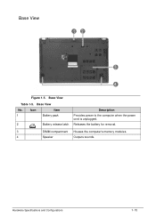
Icon Item 1 Battery pack 2 Battery release latch Description Provides power to the computer when the power cord is unplugged. Base View Table 1-5. Base View No. Base View 0 Figure 1-5. Releases the battery for removal. 3 DIMM compartment Houses the computer's memory modules. 4 Speaker Outputs sounds. Hardware Specifications and Configurations 1-15
Icon Item 1 Battery pack 2 Battery release latch Description Provides power to the computer when the power cord is unplugged. Base View Table 1-5. Base View No. Base View 0 Figure 1-5. Releases the battery for removal. 3 DIMM compartment Houses the computer's memory modules. 4 Speaker Outputs sounds. Hardware Specifications and Configurations 1-15

Acer V5-471 Notebook Service Guide
Page 33
... cm 0.78 in Weight (equipped with 6-cell 1.97 kg for UMA battery pack, HDD, and ODD) 2.01 kg for Discrete 4.343 lb for UMA 4.431 lb for Discrete Input power Operating voltage 19 V, 65 W Operating current (max) 3.42 A Temperature Operating (not writing to optical disc) 0 to 35 &#...to 60 °C -4 to 140 °F Relative humidity Operating 10% to 90% Nonoperating 5% to 95% Maximum altitude (unpressurized) Operating -15 to 3,048 m -50 to 10,000 ft Nonoperating -15 to 12,192 m -50 to 40,000 ft Shock Operating 125 g, 2 ms, half-sine TBD Nonoperating 200 g, 2 ms, half-...
... cm 0.78 in Weight (equipped with 6-cell 1.97 kg for UMA battery pack, HDD, and ODD) 2.01 kg for Discrete 4.343 lb for UMA 4.431 lb for Discrete Input power Operating voltage 19 V, 65 W Operating current (max) 3.42 A Temperature Operating (not writing to optical disc) 0 to 35 &#...to 60 °C -4 to 140 °F Relative humidity Operating 10% to 90% Nonoperating 5% to 95% Maximum altitude (unpressurized) Operating -15 to 3,048 m -50 to 10,000 ft Nonoperating -15 to 12,192 m -50 to 40,000 ft Shock Operating 125 g, 2 ms, half-sine TBD Nonoperating 200 g, 2 ms, half-...
Acer V5-471 Notebook Service Guide
Page 62
BIOS Setup Utility 2-3 Navigating the BIOS Utility 2-3 BIOS Menus 2-4 Main 2-6 Security 2-8 Boot 2-11 Exit 2-12 BIOS Flash Utilities 2-13 WinFlash Utility 2-14 Remove HDD/BIOS Password Utilities 2-15 Removing the HDD Password 2-15 Removing the BIOS Passwords 2-16 Clearing the BIOS Passwords 2-17 Using DMI Tools 2-18 LAN EEPROM Utility 2-18 2-2
BIOS Setup Utility 2-3 Navigating the BIOS Utility 2-3 BIOS Menus 2-4 Main 2-6 Security 2-8 Boot 2-11 Exit 2-12 BIOS Flash Utilities 2-13 WinFlash Utility 2-14 Remove HDD/BIOS Password Utilities 2-15 Removing the HDD Password 2-15 Removing the BIOS Passwords 2-16 Clearing the BIOS Passwords 2-17 Using DMI Tools 2-18 LAN EEPROM Utility 2-18 2-2
Acer V5-471 Notebook Service Guide
Page 75
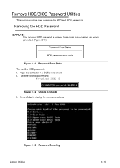
Figure 2-13. Password Encoding System Utilities 2-15 Removing the HDD Password 0 NOTE: NOTE: If the incorrect HDD password is entered three times in a DOS environment. 2. Type the following command: A\> unlock6 XXXXX 00 Figure 2-12. Remove HDD/BIOS Password Utilities 0 This section explains how to display the command options. Password Error Status To reset the HDD password: 1. Unlock Key Code 3. Open the computer in succession, an error is generated. (Figure 2-11) Password Error Status HDD password error code Figure 2-11. Press Enter to remove the HDD and BIOS passwords.
Figure 2-13. Password Encoding System Utilities 2-15 Removing the HDD Password 0 NOTE: NOTE: If the incorrect HDD password is entered three times in a DOS environment. 2. Type the following command: A\> unlock6 XXXXX 00 Figure 2-12. Remove HDD/BIOS Password Utilities 0 This section explains how to display the command options. Password Error Status To reset the HDD password: 1. Unlock Key Code 3. Open the computer in succession, an error is generated. (Figure 2-11) Password Error Status HDD password error code Figure 2-11. Press Enter to remove the HDD and BIOS passwords.
Acer V5-471 Notebook Service Guide
Page 78
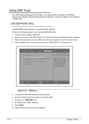
... address. Press Enter. 10. Using DMI Tools 0 The DMI (Desktop Management Interface) Tool copies BIOS information to EEPROM (Electrically Erasable Programmable Read-Only Memory). Figure 2-15. Execute the < MAC.BAT> file. 8.
... address. Press Enter. 10. Using DMI Tools 0 The DMI (Desktop Management Interface) Tool copies BIOS information to EEPROM (Electrically Erasable Programmable Read-Only Memory). Figure 2-15. Execute the < MAC.BAT> file. 8.
Acer V5-471 Notebook Service Guide
Page 80
... Modules Disassembly Flowchart 3-8 Removing the Battery Pack 3-9 Removing the DIMM Cover 3-10 Removing the DIMM Modules 3-11 Removing the ODD Module 3-12 Removing the Keyboard 3-15 Main Unit Disassembly Process 3-17 Main Unit Disassembly Flowchart 3-17 Removing the Palmrest Module/Upper Case 3-18 Removing the Touchpad Board 3-21 Removing the Power...
... Modules Disassembly Flowchart 3-8 Removing the Battery Pack 3-9 Removing the DIMM Cover 3-10 Removing the DIMM Modules 3-11 Removing the ODD Module 3-12 Removing the Keyboard 3-15 Main Unit Disassembly Process 3-17 Main Unit Disassembly Flowchart 3-17 Removing the Palmrest Module/Upper Case 3-18 Removing the Touchpad Board 3-21 Removing the Power...
Acer V5-471 Notebook Service Guide
Page 93
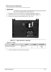
.... Remove the screw securing the keyboard to use excessive force when removing. 1. Screw Step Keyboard Disassembly Screw M2.5 × L5 Quantity 1 Screw Type 4. Machine Maintenance 3-15 Figure 3-12. Take care not to the lower case. Removing the Keyboard 0 + IMPORTANT: The keyboard is easily warped or damaged during the removal process. Perform...
.... Remove the screw securing the keyboard to use excessive force when removing. 1. Screw Step Keyboard Disassembly Screw M2.5 × L5 Quantity 1 Screw Type 4. Machine Maintenance 3-15 Figure 3-12. Take care not to the lower case. Removing the Keyboard 0 + IMPORTANT: The keyboard is easily warped or damaged during the removal process. Perform...
Acer V5-471 Notebook Service Guide
Page 95
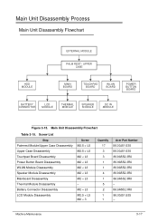
M2 × L3 M2.5 × L5 M2 × 3 Quantity 17 3 3 1 1 4 1 5 2 1 1 Acer Part Number 86.00J51.535 86.00J51.535 86.9A552.3R0 86.9A552.3R0 86.9A552.3R0 86.9A552.3R0 86.9A552.3R0 - 86.9A552.....5 × L5 M2.5 × L5 M2 × L3 M2 × L3 M2 × L3 M2 × L3 M2 × L3 - Main Unit Disassembly Flowchart Table 3-15. Main Unit Disassembly Process 0 Main Unit Disassembly Flowchart 0 EXTERNAL MODULE PALM REST / UPPER CASE HDD MODULE MAIN BOARD TOUCHPAD BOARD WLAN BOARD POWER BUTTON BOARD...
M2 × L3 M2.5 × L5 M2 × 3 Quantity 17 3 3 1 1 4 1 5 2 1 1 Acer Part Number 86.00J51.535 86.00J51.535 86.9A552.3R0 86.9A552.3R0 86.9A552.3R0 86.9A552.3R0 86.9A552.3R0 - 86.9A552.....5 × L5 M2.5 × L5 M2 × L3 M2 × L3 M2 × L3 M2 × L3 M2 × L3 - Main Unit Disassembly Flowchart Table 3-15. Main Unit Disassembly Process 0 Main Unit Disassembly Flowchart 0 EXTERNAL MODULE PALM REST / UPPER CASE HDD MODULE MAIN BOARD TOUCHPAD BOARD WLAN BOARD POWER BUTTON BOARD...
Acer V5-471 Notebook Service Guide
Page 96
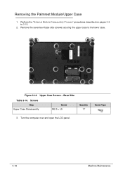
Base Side Table 3-16. Screws Step Upper Case Disassembly Screw M2.5 × L5 Quantity 17 Screw Type 3. Turn the computer over and open the LCD panel. 3-18 Machine Maintenance Remove the seventeen base side screws securing the upper case to 3-15. 2. Upper Case Screws - Removing the Palmrest Module/Upper Case 0 1. Perform the "External Module Disassembly Process" procedures described on pages 3-8 to the lower case. Figure 3-16.
Base Side Table 3-16. Screws Step Upper Case Disassembly Screw M2.5 × L5 Quantity 17 Screw Type 3. Turn the computer over and open the LCD panel. 3-18 Machine Maintenance Remove the seventeen base side screws securing the upper case to 3-15. 2. Upper Case Screws - Removing the Palmrest Module/Upper Case 0 1. Perform the "External Module Disassembly Process" procedures described on pages 3-8 to the lower case. Figure 3-16.
Acer V5-471 Notebook Service Guide
Page 160
Introduction 4-3 General Information 4-3 Power On Issues 4-4 No Display Issues 4-5 LCD Failure 4-7 Keyboard Failure 4-8 Touchpad Failure 4-9 Internal Speaker Failure 4-10 Microphone Failure 4-12 USB Failure 4-13 WLAN Failure 4-14 Bluetooth Failure 4-15 Card Reader Failure 4-16 Thermal Unit Failure 4-17 Other Functions Failure 4-18 Intermittent Problems 4-19 Undetermined Problems 4-19 Error Codes 4-20 BIOS Beep Codes 4-21 POST Codes 4-26 Component Codes 4-26 Progress Codes 4-31 4-2
Introduction 4-3 General Information 4-3 Power On Issues 4-4 No Display Issues 4-5 LCD Failure 4-7 Keyboard Failure 4-8 Touchpad Failure 4-9 Internal Speaker Failure 4-10 Microphone Failure 4-12 USB Failure 4-13 WLAN Failure 4-14 Bluetooth Failure 4-15 Card Reader Failure 4-16 Thermal Unit Failure 4-17 Other Functions Failure 4-18 Intermittent Problems 4-19 Undetermined Problems 4-19 Error Codes 4-20 BIOS Beep Codes 4-21 POST Codes 4-26 Component Codes 4-26 Progress Codes 4-31 4-2

Acer V5-471 Notebook Service Guide
Page 173
Do not replace a non-defective FRU: Figure 4-10. Bluetooth Failure Troubleshooting 4-15 Bluetooth Failure 0 If the Bluetooth fails, perform the following, one at a time.
Do not replace a non-defective FRU: Figure 4-10. Bluetooth Failure Troubleshooting 4-15 Bluetooth Failure 0 If the Bluetooth fails, perform the following, one at a time.
Acer V5-471 Notebook Service Guide
Page 193
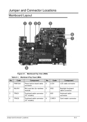
Code 1 PWRCN1 2 WLAN1 3 TPAD1 4 TPAD2 Component Power button board cable connector Mini card slot (for wireless module) Touchpad cable connector (15" models) Touchpad cable connector (14" models) No. Code 5 LCD1 6 KB2 7 KB1 8 CARD1 Component LCD cable connector Backlight keyboard cable connector Keyboard cable connector Card reader connector Jumper and Connector Locations 5-3 Mainboard Top View (UMA) No. Mainboard Top View (UMA) Table 5-1. Jumper and Connector Locations Mainboard Layout 0 Figure 5-1.
Code 1 PWRCN1 2 WLAN1 3 TPAD1 4 TPAD2 Component Power button board cable connector Mini card slot (for wireless module) Touchpad cable connector (15" models) Touchpad cable connector (14" models) No. Code 5 LCD1 6 KB2 7 KB1 8 CARD1 Component LCD cable connector Backlight keyboard cable connector Keyboard cable connector Card reader connector Jumper and Connector Locations 5-3 Mainboard Top View (UMA) No. Mainboard Top View (UMA) Table 5-1. Jumper and Connector Locations Mainboard Layout 0 Figure 5-1.
Acer V5-471 Notebook Service Guide
Page 194
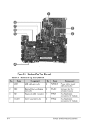
Code 1 LCD1 Component LCD cable connector No. Figure 5-2. Mainboard Top View (Discreet) Table 5-2. Code 5 PWRCN1 2 KB2 3 KB1 Backlight keyboard cable 6 connector Keyboard cable connector 7 WLAN1 TPAD1 4 CARD1 Card reader connector 8 TPAD2 Component Power button board cable connector Mini card slot (for wireless module) Touchpad cable connector (15" models) Touchpad cable connector (14" models) 5-4 Jumper and Connector Locations Mainboard Top View (Discreet) No.
Code 1 LCD1 Component LCD cable connector No. Figure 5-2. Mainboard Top View (Discreet) Table 5-2. Code 5 PWRCN1 2 KB2 3 KB1 Backlight keyboard cable 6 connector Keyboard cable connector 7 WLAN1 TPAD1 4 CARD1 Card reader connector 8 TPAD2 Component Power button board cable connector Mini card slot (for wireless module) Touchpad cable connector (15" models) Touchpad cable connector (14" models) 5-4 Jumper and Connector Locations Mainboard Top View (Discreet) No.
Acer V5-471 Notebook Service Guide
Page 195
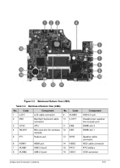
Code 9 AUSB3 10 LOUT1 11 DM2 12 DM1 13 SPK1 6 HDMI1 7 AUSB1 8 AUSB2 HDMI port USB 3.0 port USB 2.0 port 14 HDD2 15 RTC1 16 ODD1 Component USB 2.0 port Headphones/ speaker/ line-out jack port DIMM slot 2 DIMM slot 1 Speaker cable connector HDD cable connector RTC battery ODD connector Jumper and Connector Locations 5-5 Mainboard Bottom View (UMA) No. Mainboard Bottom View (UMA) Table 5-3. Code 1 LCD1 2 KB2 3 CPU1 4 WLAN1 5 FT1 Component LCD cable connector Backlight keyboard cable connector CPU Mini card slot (for wireless module) Feature port No. Figure 5-3.
Code 9 AUSB3 10 LOUT1 11 DM2 12 DM1 13 SPK1 6 HDMI1 7 AUSB1 8 AUSB2 HDMI port USB 3.0 port USB 2.0 port 14 HDD2 15 RTC1 16 ODD1 Component USB 2.0 port Headphones/ speaker/ line-out jack port DIMM slot 2 DIMM slot 1 Speaker cable connector HDD cable connector RTC battery ODD connector Jumper and Connector Locations 5-5 Mainboard Bottom View (UMA) No. Mainboard Bottom View (UMA) Table 5-3. Code 1 LCD1 2 KB2 3 CPU1 4 WLAN1 5 FT1 Component LCD cable connector Backlight keyboard cable connector CPU Mini card slot (for wireless module) Feature port No. Figure 5-3.
Acer V5-471 Notebook Service Guide
Page 196
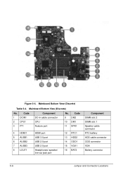
Figure 5-4. Mainboard Bottom View (Discrete) Table 5-4. Mainboard Bottom View (Discrete) No. Code 1 DCIN1 2 CPU1 3 FT1 Component DC-In cable connector CPU Feature port No. Code 9 DM2 10 DM1 11 SPK1 4 HDMI1 5 AUSB1 6 AUSB2 7 AUSB3 8 LOUT1 HDMI port USB 3.0 port USB 2.0 port USB 2.0 port Headphones/ speaker/ line-out jack port 12 RTC1 13 HDD2 14 ODD1 15 VGA1 16 BAT2 Component DIMM slot 2 DIMM slot 1 Speaker cable connector RTC battery HDD cable connector ODD connector VGA Battery connector 5-6 Jumper and Connector Locations
Figure 5-4. Mainboard Bottom View (Discrete) Table 5-4. Mainboard Bottom View (Discrete) No. Code 1 DCIN1 2 CPU1 3 FT1 Component DC-In cable connector CPU Feature port No. Code 9 DM2 10 DM1 11 SPK1 4 HDMI1 5 AUSB1 6 AUSB2 7 AUSB3 8 LOUT1 HDMI port USB 3.0 port USB 2.0 port USB 2.0 port Headphones/ speaker/ line-out jack port 12 RTC1 13 HDD2 14 ODD1 15 VGA1 16 BAT2 Component DIMM slot 2 DIMM slot 1 Speaker cable connector RTC battery HDD cable connector ODD connector VGA Battery connector 5-6 Jumper and Connector Locations
Acer V5-471 Notebook Service Guide
Page 205
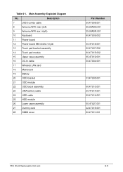
... (left) 9 Antenna WIFI aux. (right) 10 Keyboard 11 Power board 12 Power board EMI shield / mylar 13 Touch pad bracket assembly 14 Touch pad module 15 Upper case assembly 16 DC-In cable 17 Wireless LAN card 18 Mainboard 19 Battery 20 ODD bracket 21 ODD module 22 ODD bezel assembly...
... (left) 9 Antenna WIFI aux. (right) 10 Keyboard 11 Power board 12 Power board EMI shield / mylar 13 Touch pad bracket assembly 14 Touch pad module 15 Upper case assembly 16 DC-In cable 17 Wireless LAN card 18 Mainboard 19 Battery 20 ODD bracket 21 ODD module 22 ODD bezel assembly...


