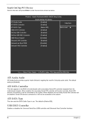
Acer Aspire M1100 Motherboard

Related Manual Pages
Similar Questions

My Acer Aspire Ax3400 Needs A New Cmos Battery Were Is It On The Motherboard
my acer aspire ax3400 needs a new cmos battery were is it on the motherboard
my acer aspire ax3400 needs a new cmos battery were is it on the motherboard
(Posted by powellthomas95 3 years ago)
My 3600 Motherboard
my 3600 motherboard must be changed.can i find anotheronecompatible?
my 3600 motherboard must be changed.can i find anotheronecompatible?
(Posted by olaerud 10 years ago)


Aspire M1100 Motherboard - B1300a Be 2300
Hello - I need to get a new motherboard for my accer aspire m1100 computer? I have 3 gigs of ram and...
Hello - I need to get a new motherboard for my accer aspire m1100 computer? I have 3 gigs of ram and...
(Posted by webmaster51502 10 years ago)
Related Terms
The following terms were also used when searching for Acer Aspire M1100 Motherboard:- acer aspire m1100
- aspire m1100
- acer aspire m1100 motherboard
- aspire m1100 driver
- acer aspire m1100 driver
- acer aspire m1100 b1300a
- aspire m1100 b1300a
- aspire m1100 motherboard
- acer aspire m1100 drivers
- acer aspire m1100 recovery
- aspire m1100 recovery
- aspire m1100 bios
- aspire m1100 drivers
- aspire m1100 memory
- aspire m1100 ram
- acer aspire m1100 spec
- acer aspire m1100 xp driver
- acer aspire m1100 ram
- acer aspire m1100 recovery disk
- aspire m1100 spec
- aspire m1100 windows 7
- acer aspire m1100 manual
- acer aspire m1100 u1402a
- acer aspire m1100 windows 7
- aspire m1100 u1402a
- acer aspire m1100 driver download
- aspire m1100 manual
- aspire m1100 xp driver
- acer aspire m1100 specs
- aspire m1100 b1410a
- aspire m1100 bios update
- aspire m1100 driver download
- aspire m1100 recovery disk
- aspire m1100 windows 7 drivers
- acer aspire m1100 b1410a
- aspire m1100 memory upgrade
- aspire m1100 processor
- aspire m1100 specs
- aspire m1100-b1300a motherboard
- aspire m1100-b1410a
- acer aspire m1100 3.0 download windows 7
- acer aspire m1100 400w power supply
- acer aspire m1100 am1100 - u1402a
- acer aspire m1100 am1100-b1410a
- acer aspire m1100 amd motherboard
- acer aspire m1100 audio windows vista
- acer aspire m1100 bios
- acer aspire m1100 bios update
- acer aspire m1100 card reader
- acer aspire m1100 card reader driver
- acer aspire m1100 clear cmos
- acer aspire m1100 compatible motherboard
- acer aspire m1100 cpu upgrade
- acer aspire m1100 desktop
- acer aspire m1100 desktop computer schematic
- acer aspire m1100 desktop pc
- acer aspire m1100 diagram
- acer aspire m1100 download
- acer aspire m1100 download windows 7
- acer aspire m1100 drivers windows 7
- acer aspire m1100 ethernet driver
- acer aspire m1100 graphics card
- acer aspire m1100 hard drive
- acer aspire m1100 hard drive removal
- acer aspire m1100 manual pdf
- acer aspire m1100 maximum ram
- acer aspire m1100 memory
- acer aspire m1100 memory upgrade
- acer aspire m1100 memory upgrade instructions
- acer aspire m1100 motherboard diagram
- acer aspire m1100 motherboard for sale
- acer aspire m1100 motherboard layout
- acer aspire m1100 motherboard manual
- acer aspire m1100 motherboard specifications
- acer aspire m1100 motherboard specs
- acer aspire m1100 no display
- acer aspire m1100 no video
- acer aspire m1100 no video no beeps
- acer aspire m1100 overclock
- acer aspire m1100 parts
- acer aspire m1100 power supply
- acer aspire m1100 power supply replacement
- acer aspire m1100 price
- acer aspire m1100 problems
- acer aspire m1100 processor
- acer aspire m1100 processor upgrade
- acer aspire m1100 ram upgrade
- acer aspire m1100 recovery disk download
- acer aspire m1100 replacement motherboard
- acer aspire m1100 reset cmos
- acer aspire m1100 restore
- acer aspire m1100 restore disk
- acer aspire m1100 restore factory settings
- acer aspire m1100 says no signal on monitor
- acer aspire m1100 sm bus controller
- acer aspire m1100 specifications
- acer aspire m1100 support
- acer aspire m1100 system restore cd
- acer aspire m1100 tower
- acer aspire m1100 upgrade
- acer aspire m1100 upgrade motherboard
- acer aspire m1100 upgrades
- acer aspire m1100 video card
- acer aspire m1100 video card upgrade
- acer aspire m1100 will not boot
- acer aspire m1100 windows 7 drivers
- acer aspire m1100 windows vista
- acer aspire m1100 won't boot
- acer aspire m1100 won't post
- acer aspire m1100 won't turn on
- acer aspire m1100-b1300a
- acer aspire m1100-b1300a motherboard
- acer aspire m1100-b1410a
- acer aspire m1100-u1402a
- acer aspire m1100/video card
- acer aspirem1100
- acer aspirem1100 desktop pc
- aspire m1100 1.9 ghz
- aspire m1100 3.0 download windows 7
- aspire m1100 400w power supply
- aspire m1100 am1100 - u1402a
- aspire m1100 am1100-b1410a
- aspire m1100 amd motherboard
- aspire m1100 audio driver
- aspire m1100 audio windows vista
- aspire m1100 bios download
- aspire m1100 bios driver
- aspire m1100 bios update download
- aspire m1100 card reader
- aspire m1100 card reader driver
- aspire m1100 chipset
- aspire m1100 clear cmos
- aspire m1100 compatible motherboard
- aspire m1100 cpu
- aspire m1100 cpu upgrade
- aspire m1100 desktop
- aspire m1100 desktop computer schematic
- aspire m1100 diagram
- aspire m1100 download
- aspire m1100 download windows 7
- aspire m1100 driver xp
- aspire m1100 drivers download
- aspire m1100 drivers ethernet
- aspire m1100 drivers windows 7
- aspire m1100 drivers windows xp
- aspire m1100 drivers xp
- aspire m1100 ethernet driver
- aspire m1100 f10
- aspire m1100 graphics card
- aspire m1100 hard drive
- aspire m1100 hard drive removal
- aspire m1100 manual pdf
- aspire m1100 maximum ram
- aspire m1100 memory upgrade instructions
- aspire m1100 motherboard diagram
- aspire m1100 motherboard for sale
- aspire m1100 motherboard layout
- aspire m1100 motherboard manual
- aspire m1100 motherboard service manual
- aspire m1100 motherboard specifications
- aspire m1100 motherboard specs
- aspire m1100 no display
- aspire m1100 no video
- aspire m1100 no video no beeps
- aspire m1100 overclock
- aspire m1100 parts
- aspire m1100 photo
- aspire m1100 power supply
- aspire m1100 power supply replacement
- aspire m1100 price
- aspire m1100 problems
- aspire m1100 processor upgrade
- aspire m1100 ram upgrade
- aspire m1100 recovery disk download
- aspire m1100 replacement motherboard
- aspire m1100 reset cmos
- aspire m1100 restore
- aspire m1100 restore disk
- aspire m1100 restore factory settings
- aspire m1100 says no signal on monitor
- aspire m1100 series
- aspire m1100 service manual
- aspire m1100 sm bus controller
- aspire m1100 specifications
- aspire m1100 stopped booting
- aspire m1100 support
- aspire m1100 system restore cd
- aspire m1100 tower
- aspire m1100 troubleshooting guide
- aspire m1100 upgrade
- aspire m1100 upgrade motherboard
- aspire m1100 upgrades
- aspire m1100 video card
- aspire m1100 video card upgrade
- aspire m1100 will not boot
- aspire m1100 windows vista
- aspire m1100 won't boot
- aspire m1100 won't post
- aspire m1100 won't turn on
- aspire m1100-b1300a
- aspire m1100-u1402a
- aspire m1100/video card