
Service Guide
Page 17
... ("Run Setup" message) to make sure that you close the Setup. The screenshots used in your system. These values may be simply referred to as "BIOS", "Setup", or "Setup utility" in CMOS. NOTE: CMOS Setup Utility will need to run this utility. Chapter 2 9 Before you run the CMOS Setup Utility, make...
... ("Run Setup" message) to make sure that you close the Setup. The screenshots used in your system. These values may be simply referred to as "BIOS", "Setup", or "Setup utility" in CMOS. NOTE: CMOS Setup Utility will need to run this utility. Chapter 2 9 Before you run the CMOS Setup Utility, make...

Service Guide
Page 19
... to the six primary CMOS Setup menus, namely: • Product Information • Standard CMOS Features • Advanced BIOS Features • Advanced Chipset Features • Integrated Peripherals • Power Management Setup • PC Health Status • Frequency/Voltage Control •...; BIOS Security Features • Load Optimized Defaults • Save & Exit Setup • Exit Without Saving In the descriptive table following each...
... to the six primary CMOS Setup menus, namely: • Product Information • Standard CMOS Features • Advanced BIOS Features • Advanced Chipset Features • Integrated Peripherals • Power Management Setup • PC Health Status • Frequency/Voltage Control •...; BIOS Security Features • Load Optimized Defaults • Save & Exit Setup • Exit Without Saving In the descriptive table following each...
Service Guide
Page 22
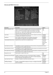
...it lets the OS configure Plug and Play (PnP) devices not required for Num Lock. Yes When set to yes, it lets the BIOS configure all the devices in the system. Optical Disk Drive Priority Press Enter to write data into this area. Quick Boot Allows you to ...previously saved Extended No System Configuration Data (ESCD) data and reconfigure the settings. If enabled, BIOS will show a warning message on state for boot if the system has a PnP OS. Advanced BIOS Features Parameter Description Option Reset Configuration Data Allows you to decrease the time it takes to boot...
...it lets the OS configure Plug and Play (PnP) devices not required for Num Lock. Yes When set to yes, it lets the BIOS configure all the devices in the system. Optical Disk Drive Priority Press Enter to write data into this area. Quick Boot Allows you to ...previously saved Extended No System Configuration Data (ESCD) data and reconfigure the settings. If enabled, BIOS will show a warning message on state for boot if the system has a PnP OS. Advanced BIOS Features Parameter Description Option Reset Configuration Data Allows you to decrease the time it takes to boot...

Service Guide
Page 26
... Enabled Disabled 18 Chapter 2 PC Health Status Parameter CPU Warning Temperature Description Sets the warning threshold for processor temperature. When processor temperature exceeds the threshold, BIOS will emit warning sound. CPU Shutdown Temperature Sets the processor shutdown temperature.
... Enabled Disabled 18 Chapter 2 PC Health Status Parameter CPU Warning Temperature Description Sets the warning threshold for processor temperature. When processor temperature exceeds the threshold, BIOS will emit warning sound. CPU Shutdown Temperature Sets the processor shutdown temperature.
Service Guide
Page 29
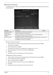
...press Enter. Use the up /down arrow keys to select Change Supervisor Password menu then press Enter. 2. Retype the password to the BIOS Setup Utility. Press Enter to change the User password. User password is set. The password may consist up access passwords. Setting a ...then press Enter. 4. Chapter 2 21 User password is available only when a Supervisor password is used to control entry access to the BIOS Setup Utility. Select Yes to save the new password and close the Setup Utility. Parameter Supervisor Password User Password Change Supervisor Password Set...
...press Enter. Use the up /down arrow keys to select Change Supervisor Password menu then press Enter. 2. Retype the password to the BIOS Setup Utility. Press Enter to change the User password. User password is set. The password may consist up access passwords. Setting a ...then press Enter. 4. Chapter 2 21 User password is available only when a Supervisor password is used to control entry access to the BIOS Setup Utility. Select Yes to save the new password and close the Setup Utility. Parameter Supervisor Password User Password Change Supervisor Password Set...

Service Guide
Page 31
Chapter 2 23 If you are quite demanding in terms of low-performance components and you to load these settings, the system might not function properly. Setup defaults are using low-speed memory chips or other kinds of resources consumption. Load Optimized Defaults The Load Optimized Defaults menu allows you choose to load the default settings for all BIOS setup parameters.
Chapter 2 23 If you are quite demanding in terms of low-performance components and you to load these settings, the system might not function properly. Setup defaults are using low-speed memory chips or other kinds of resources consumption. Load Optimized Defaults The Load Optimized Defaults menu allows you choose to load the default settings for all BIOS setup parameters.

Service Guide
Page 74
... to the 0 position. 3. Make sure the main power switch is set to the system and AC source. Remove the system covers. Verify that components are Acer-qualified and supported. 11. Power on a flat, stable surface. 7. System Check Procedures Power System Check If the system will not power on, check if the... power cable is not evident, you can try viewing the POST messages and BIOS event logs during the system startup. 66 Chapter 4 Replace the system covers. 12.
... to the 0 position. 3. Make sure the main power switch is set to the system and AC source. Remove the system covers. Verify that components are Acer-qualified and supported. 11. Power on a flat, stable surface. 7. System Check Procedures Power System Check If the system will not power on, check if the... power cable is not evident, you can try viewing the POST messages and BIOS event logs during the system startup. 66 Chapter 4 Replace the system covers. 12.
Service Guide
Page 75
... actions in the sequence shown in FRU/Action column, if the FRU replacement does not solve the problem, put the original part back in the BIOS Setup Utility menus, reset the computer, enter Setup and install Setup defaults or correct the error. The error messages in the following table indicate the...
... actions in the sequence shown in FRU/Action column, if the FRU replacement does not solve the problem, put the original part back in the BIOS Setup Utility menus, reset the computer, enter Setup and install Setup defaults or correct the error. The error messages in the following table indicate the...

Service Guide
Page 77
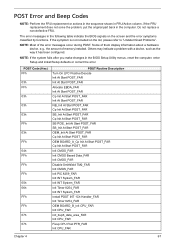
... POST Routine Description CRB_Init At Early POST_FAR Cp Init At Early POST_FAR Init GPNV Area_FAR Init BIOS Modules_FAR Process SMBIOS Module_far Init GPNV Area_FAR Init Language Modules_FAR Init BIOS Modules_FAR Init Osb CMOS_FAR Init Silent Logo Module_FAR Init Silent Logo Module_FAR Init... BIOS Modules_FAR Save OEM LOGO Size_FAR Init Silent Logo Module_FAR Init BIOS Modules_FAR Global Device Init At Early POST_FAR Add IOITE8718ToMB...
... POST Routine Description CRB_Init At Early POST_FAR Cp Init At Early POST_FAR Init GPNV Area_FAR Init BIOS Modules_FAR Process SMBIOS Module_far Init GPNV Area_FAR Init Language Modules_FAR Init BIOS Modules_FAR Init Osb CMOS_FAR Init Silent Logo Module_FAR Init Silent Logo Module_FAR Init... BIOS Modules_FAR Save OEM LOGO Size_FAR Init Silent Logo Module_FAR Init BIOS Modules_FAR Global Device Init At Early POST_FAR Add IOITE8718ToMB...

Service Guide
Page 78
... BOARD_R_Display Memory Info_FAR NB_Display BIOS Info_FAR SB_Display BIOS Info_FAR Cp Display BIOS Info_FAR OEM_Display BIOS Info_FAR Cp Display BIOS Info_FAR Check ROM SIP Overwrite_FAR Cp Display BIOS Info_FAR C72_Check Gpu Loc_FAR Cp Display BIOS Info_FAR NVMM_Display BIOS Info_FAR Cp Display BIOS Info_FAR Display Setup Key Msg_FAR Display BIOS Info_FAR OEMBOARD_A_Display BIOS Info_FAR Display BIOS Info_FAR OC_Default_Display BIOS Info_FAR OEM BOARD_A_Display BIOS Info_FAR DIM Device...
... BOARD_R_Display Memory Info_FAR NB_Display BIOS Info_FAR SB_Display BIOS Info_FAR Cp Display BIOS Info_FAR OEM_Display BIOS Info_FAR Cp Display BIOS Info_FAR Check ROM SIP Overwrite_FAR Cp Display BIOS Info_FAR C72_Check Gpu Loc_FAR Cp Display BIOS Info_FAR NVMM_Display BIOS Info_FAR Cp Display BIOS Info_FAR Display Setup Key Msg_FAR Display BIOS Info_FAR OEMBOARD_A_Display BIOS Info_FAR Display BIOS Info_FAR OC_Default_Display BIOS Info_FAR OEM BOARD_A_Display BIOS Info_FAR DIM Device...

Service Guide
Page 80
... System RAM_FAR Global Device Init At Mid POST_FAR Init KB CAt Mid POST_FAR Global Device Init At Mid POST_FAR Clear BIOS Version Info_FAR Init IPL Devices_FAR far Display USB Devices Clear BIOS Version Info_FAR Setup Int13 Before Init_FAR Init IPLDevices_FAR Init PnP ATA Data_FAR Setup Int13 Before Init_FAR OEM BOARD_B_init_ata_channel_info_FAR init_ata_channel_info_FAR init_ata_channel_info_FAR...
... System RAM_FAR Global Device Init At Mid POST_FAR Init KB CAt Mid POST_FAR Global Device Init At Mid POST_FAR Clear BIOS Version Info_FAR Init IPL Devices_FAR far Display USB Devices Clear BIOS Version Info_FAR Setup Int13 Before Init_FAR Init IPLDevices_FAR Init PnP ATA Data_FAR Setup Int13 Before Init_FAR OEM BOARD_B_init_ata_channel_info_FAR init_ata_channel_info_FAR init_ata_channel_info_FAR...

Service Guide
Page 81
... Restore Shadow State_FAR Init IPL Devices_FAR BBS Finale_FAR Init IPL Devices_FAR Restore Display Mode_FAR Init IPL Devices_FAR SB_Before_Setup_Check_VT Init IPL Devices_FAR Init IPL Devices_FAR Log BIOS Errors_FAR Process POST Errors_FAR Process SMBIOS Module Late Post_far Process POST Errors_FAR Process POST Errors_FAR ACER_Check Boot Password_FAR Check Boot Password_FAR Cpu Prepare For Cmos...
... Restore Shadow State_FAR Init IPL Devices_FAR BBS Finale_FAR Init IPL Devices_FAR Restore Display Mode_FAR Init IPL Devices_FAR SB_Before_Setup_Check_VT Init IPL Devices_FAR Init IPL Devices_FAR Log BIOS Errors_FAR Process POST Errors_FAR Process SMBIOS Module Late Post_far Process POST Errors_FAR Process POST Errors_FAR ACER_Check Boot Password_FAR Check Boot Password_FAR Cpu Prepare For Cmos...

Service Guide
Page 83
... Prepare System For OS_FAR BBS BeforeI19_FAR Uninstall POST INT09h Handler_FAR ACPIS4Set Boot Drive_FAR BBS BeforeI19_FAR OEM BOARD_A_Prepare System For OS_FAR Prepare System For OS_FAR Log BIOS Errors_FAR Init At End POST_FAR Cp Init At End POST_FAR Init At End POST_FAR NB_Init At End POST_FAR Cp Init At End POST_FAR SB_Init At...
... Prepare System For OS_FAR BBS BeforeI19_FAR Uninstall POST INT09h Handler_FAR ACPIS4Set Boot Drive_FAR BBS BeforeI19_FAR OEM BOARD_A_Prepare System For OS_FAR Prepare System For OS_FAR Log BIOS Errors_FAR Init At End POST_FAR Cp Init At End POST_FAR Init At End POST_FAR NB_Init At End POST_FAR Cp Init At End POST_FAR SB_Init At...

Service Guide
Page 85
... help you repair the desktop computer. Chapter 4 77 These can download information materials for all of Acer notebook, desktop and server models including: • Service guides for all models • User's manuals • Training materials • BIOS updates • Software utilities • Spare parts lists • Technical Announcement Bulletins (TABs) For these...
... help you repair the desktop computer. Chapter 4 77 These can download information materials for all of Acer notebook, desktop and server models including: • Service guides for all models • User's manuals • Training materials • BIOS updates • Software utilities • Spare parts lists • Technical Announcement Bulletins (TABs) For these...

Service Guide
Page 90
... the positive and should be connected to GND. SYSFAN1-3 support fan control, too. SATA1~6 stack SATA connectors are both available for the SYS FAN1/2/3 in BIOS. 82 Chapter 5 CONTROL SE NS OR +1 2V GND CPUFAN1 SE NS OR +1 2V GND SYSFAN1/2/3 NC +1 2V GND SYSFAN4/5 IMPORTANT:Fan cooler set with +12V...
... the positive and should be connected to GND. SYSFAN1-3 support fan control, too. SATA1~6 stack SATA connectors are both available for the SYS FAN1/2/3 in BIOS. 82 Chapter 5 CONTROL SE NS OR +1 2V GND CPUFAN1 SE NS OR +1 2V GND SYSFAN1/2/3 NC +1 2V GND SYSFAN4/5 IMPORTANT:Fan cooler set with +12V...


