
Quick Start Guide
Page 6
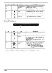
Brightness up Increases the sound volume. Charging: The light shows amber when the battery is closed up. Fully charged: The light shows blue when in AC mode. 2 Multi-in-1 Accepts Secure Digital (SD), MultiMediaCard card (MMC), Memory...time. 1. Volume down Decreases the screen brightness. The front panel indicators are visible even when the computer cover is charging. 2. Battery1 Indicates the computer's battery status. 1. Note: Push to remove/install the card. Brightness down Decreases the sound volume. Volume up Increases the screen brightness. Closed front view #...
Brightness up Increases the sound volume. Charging: The light shows amber when the battery is closed up. Fully charged: The light shows blue when in AC mode. 2 Multi-in-1 Accepts Secure Digital (SD), MultiMediaCard card (MMC), Memory...time. 1. Volume down Decreases the screen brightness. The front panel indicators are visible even when the computer cover is charging. 2. Battery1 Indicates the computer's battery status. 1. Note: Push to remove/install the card. Brightness down Decreases the sound volume. Volume up Increases the screen brightness. Closed front view #...

Quick Start Guide
Page 9
Note: Do not cover or obstruct the opening of the fan. 9 Base view English # Icon Item 1 Battery bay Description Houses the computer's battery pack. 2 Battery release latch Releases the battery for certain models only). 5 Hard disk bay-Main Houses the computer's hard disk (secured with screws). 6 Memory compartment Houses the computer's main memory. 7... Enable the computer to stay cool, even cooling fan after prolonged use. Secondary Houses the computer's hard disk (secured with screws) (for removal. 3 Battery lock Locks the battery in position. 4 Hard disk bay-
Note: Do not cover or obstruct the opening of the fan. 9 Base view English # Icon Item 1 Battery bay Description Houses the computer's battery pack. 2 Battery release latch Releases the battery for certain models only). 5 Hard disk bay-Main Houses the computer's hard disk (secured with screws). 6 Memory compartment Houses the computer's main memory. 7... Enable the computer to stay cool, even cooling fan after prolonged use. Secondary Houses the computer's hard disk (secured with screws) (for removal. 3 Battery lock Locks the battery in position. 4 Hard disk bay-
Quick Start Guide
Page 10
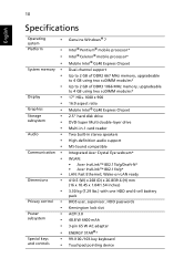
Wake-on-LAN ready 410.5 (W) x 268 (D) x 26.8/39.6 (H) mm (16 x 10.45 x 1.04/1.54 inches) 3.30 kg (7.29 lbs.) with one HDD and 6-cell battery pack BIOS user, supervisor, HDD passwords Kensington lock slot ACPI 3.0 48.8 W 4400 mAh 3-pin 65 W AC adapter ENERGY STAR®* 99-/100-/103-key keyboard ... disk drive DVD-Super Multi double-layer drive Multi-in-1 card reader Two built-in stereo speakers High-definition audio support MS-Sound compatible Integrated Acer Crystal Eye webcam* WLAN: • Acer InviLink™ 802.11b/g/Draft-N* • Acer InviLink™ 802.11b/g* LAN: Fast Ethernet;
Wake-on-LAN ready 410.5 (W) x 268 (D) x 26.8/39.6 (H) mm (16 x 10.45 x 1.04/1.54 inches) 3.30 kg (7.29 lbs.) with one HDD and 6-cell battery pack BIOS user, supervisor, HDD passwords Kensington lock slot ACPI 3.0 48.8 W 4400 mAh 3-pin 65 W AC adapter ENERGY STAR®* 99-/100-/103-key keyboard ... disk drive DVD-Super Multi double-layer drive Multi-in-1 card reader Two built-in stereo speakers High-definition audio support MS-Sound compatible Integrated Acer Crystal Eye webcam* WLAN: • Acer InviLink™ 802.11b/g/Draft-N* • Acer InviLink™ 802.11b/g* LAN: Fast Ethernet;

Service Guide
Page 7
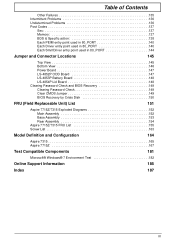
Table of Contents System Specifications 1 Features 1 System Block Diagram 3 Your Acer Notebook tour 4 Front View 4 Closed Front View 5 Rear View 6 Left View 6 Right View 7 Bottom View 7 Indicators 8 TouchPad Basics 9 Using the Keyboard 10 ...Replacement 43 Disassembly Requirements 43 Pre-disassembly Instructions 44 Disassembly Process 44 External Module Disassembly Process 45 External Modules Disassembly Flowchart 45 Removing the Battery Pack 46 Removing the SD Dummy Card 47 Removing the Lower Covers 48 Removing the Optical Drive Module 49 Removing the DIMM Modules 51...
Table of Contents System Specifications 1 Features 1 System Block Diagram 3 Your Acer Notebook tour 4 Front View 4 Closed Front View 5 Rear View 6 Left View 6 Right View 7 Bottom View 7 Indicators 8 TouchPad Basics 9 Using the Keyboard 10 ...Replacement 43 Disassembly Requirements 43 Pre-disassembly Instructions 44 Disassembly Process 44 External Module Disassembly Process 45 External Modules Disassembly Flowchart 45 Removing the Battery Pack 46 Removing the SD Dummy Card 47 Removing the Lower Covers 48 Removing the Optical Drive Module 49 Removing the DIMM Modules 51...

Service Guide
Page 8
...Removing the Left Speaker Module 68 Removing the Right Speaker Module 70 Removing the TouchPad Bracket 72 Removing the Mainboard 74 Removing the RTC Battery 75 Removing the Thermal Module 76 Removing the CPU Fan 78 Removing the CPU 80 LCD Module Disassembly Process 81 LCD Module Disassembly ...118 Replacing the DIMM Modules 118 Replacing the ODD Module 119 Replacing the Lower Covers 119 Replacing the SD Dummy Card 120 Replacing the Battery 121 Troubleshooting 123 Common Problems 123 Power On Issue 124 No Display Issue 125 Random Loss of BIOS Settings 126 LCD Failure 127 ...
...Removing the Left Speaker Module 68 Removing the Right Speaker Module 70 Removing the TouchPad Bracket 72 Removing the Mainboard 74 Removing the RTC Battery 75 Removing the Thermal Module 76 Removing the CPU Fan 78 Removing the CPU 80 LCD Module Disassembly Process 81 LCD Module Disassembly ...118 Replacing the DIMM Modules 118 Replacing the ODD Module 119 Replacing the Lower Covers 119 Replacing the SD Dummy Card 120 Replacing the Battery 121 Troubleshooting 123 Common Problems 123 Power On Issue 124 No Display Issue 125 Random Loss of BIOS Settings 126 LCD Failure 127 ...
Service Guide
Page 9
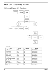
... 147 LS-4853P Battery Board 148 LS-4854P Lid Board 148 Clearing Password Check and BIOS Recovery 149 Clearing Password Check 149 Clear CMOS Jumper 149 BIOS Recovery by Crisis Disk 150 FRU (Field Replaceable Unit) List 151 Aspire 7715Z/7315 Exploded Diagrams ...152 Main Assembly 152 Base Assembly 153 Rear Assembly 154 Aspire 7715Z/7315 FRU List 155 Screw List 163 Model Definition and Configuration 164 Aspire 7315 165 Aspire 7715Z 167 Test Compatible Components 181 Microsoft® Windows...
... 147 LS-4853P Battery Board 148 LS-4854P Lid Board 148 Clearing Password Check and BIOS Recovery 149 Clearing Password Check 149 Clear CMOS Jumper 149 BIOS Recovery by Crisis Disk 150 FRU (Field Replaceable Unit) List 151 Aspire 7715Z/7315 Exploded Diagrams ...152 Main Assembly 152 Base Assembly 153 Rear Assembly 154 Aspire 7715Z/7315 FRU List 155 Screw List 163 Model Definition and Configuration 164 Aspire 7315 165 Aspire 7715Z 167 Test Compatible Components 181 Microsoft® Windows...
Service Guide
Page 12
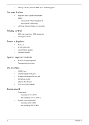
...; Humidity (non-condensing): • Operating: 20% to 80% • Non-operating: 20% to 80% 2 Chapter 1 • 3.30 kg (7.29 lbs.) with one HDD and 6-cell battery pack Communication • Integrated Acer Crystal Eye webcam* • WLAN: • Acer InviLink™ 802.11b/g/Draft-N* • Acer InviLink™ 802.11b/g* • LAN: Fast Ethernet;
...; Humidity (non-condensing): • Operating: 20% to 80% • Non-operating: 20% to 80% 2 Chapter 1 • 3.30 kg (7.29 lbs.) with one HDD and 6-cell battery pack Communication • Integrated Acer Crystal Eye webcam* • WLAN: • Acer InviLink™ 802.11b/g/Draft-N* • Acer InviLink™ 802.11b/g* • LAN: Fast Ethernet;
Service Guide
Page 15
Lights up when Num Lock is activated. Charging: The light shows amber when the battery is closed Chapter 1 5 NOTE: 1 The front panel indicators are visible even when the computer cover is charging. 2. Indicates when the hard disk drive ... reader (MMC), Memory Stick (MS), Memory Stick PRO (MS PRO), xDPicture Card (xD). NOTE: Push to remove/install the card. Battery1 Indicates the computer's battery status. 1. No. 7 8 9 Icon Item Click buttons (left and right) Palmrest HDD Description The left and right buttons function like the left and right mouse...
Lights up when Num Lock is activated. Charging: The light shows amber when the battery is closed Chapter 1 5 NOTE: 1 The front panel indicators are visible even when the computer cover is charging. 2. Indicates when the hard disk drive ... reader (MMC), Memory Stick (MS), Memory Stick PRO (MS PRO), xDPicture Card (xD). NOTE: Push to remove/install the card. Battery1 Indicates the computer's battery status. 1. No. 7 8 9 Icon Item Click buttons (left and right) Palmrest HDD Description The left and right buttons function like the left and right mouse...

Service Guide
Page 17
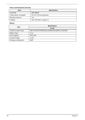
...off . Note: Wrap the computer security lock cable around an immovable object such as a table or handle of a locked drawer. Releases the battery for removal. Note: Insert a paper clip into the notch and turn the key to secure the lock. Chapter 1 7 Some keyless models are... also available. Bottom View No. 1 2 Icon Item Battery bay Battery release latch Description Houses the computer's battery pack. Lights up when the optical drive is turned off . Right View No. 1 2 3 4 5 Item Description Optical drive ...
...off . Note: Wrap the computer security lock cable around an immovable object such as a table or handle of a locked drawer. Releases the battery for removal. Note: Insert a paper clip into the notch and turn the key to secure the lock. Chapter 1 7 Some keyless models are... also available. Bottom View No. 1 2 Icon Item Battery bay Battery release latch Description Houses the computer's battery pack. Lights up when the optical drive is turned off . Right View No. 1 2 3 4 5 Item Description Optical drive ...

Service Guide
Page 18
... The computer has several easy-to stay cool, even after and cooling fan prolonged use. Charging: The light shows amber when the battery is active. Lights up when Caps Lock is closed. Battery HDD Num Lock Caps Lock Indicates the computer's battery status. No. 3 Icon Item Battery lock Description Locks the battery in AC mode.
... The computer has several easy-to stay cool, even after and cooling fan prolonged use. Charging: The light shows amber when the battery is active. Lights up when Caps Lock is closed. Battery HDD Num Lock Caps Lock Indicates the computer's battery status. No. 3 Icon Item Battery lock Description Locks the battery in AC mode.
Service Guide
Page 28
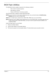
Power and Keyboard Controller Item Controller Total number of keypads Specification ENE KB926 99-/100-/103-key keyboard Windows logo key Hotkeys Yes See "Hot Keys" on page 12. Battery Item Vendor & model name Battery Type Pack capacity Normal Voltage Package configuration Specification 6 Cell SANYO/SONY/PANASONIC/SAMSUNG/SIMPLO AS2009A Li-ion 4400 mAh 2.2 Ah 3S2P 18 Chapter 1
Power and Keyboard Controller Item Controller Total number of keypads Specification ENE KB926 99-/100-/103-key keyboard Windows logo key Hotkeys Yes See "Hot Keys" on page 12. Battery Item Vendor & model name Battery Type Pack capacity Normal Voltage Package configuration Specification 6 Cell SANYO/SONY/PANASONIC/SAMSUNG/SIMPLO AS2009A Li-ion 4400 mAh 2.2 Ah 3S2P 18 Chapter 1
Service Guide
Page 43
... the Phlash. 1. Fellow the steps below to finish BIOS flash, you use the Phlash. Chapter 2 33 The flash utility has auto-execution function. If the battery pack does not contain enough power to run the Phlash utility. NOTE: Do not install memory-related drivers (XMS, EMS, DPMI) when you may not...
... the Phlash. 1. Fellow the steps below to finish BIOS flash, you use the Phlash. Chapter 2 33 The flash utility has auto-execution function. If the battery pack does not contain enough power to run the Phlash utility. NOTE: Do not install memory-related drivers (XMS, EMS, DPMI) when you may not...

Service Guide
Page 54
Remove the battery pack. Pre-disassembly Instructions Before proceeding with the disassembly procedure, make sure that order. Disassembly Process IMPORTANT: The LCD Module cannot be replaced. The disassembly ...
Remove the battery pack. Pre-disassembly Instructions Before proceeding with the disassembly procedure, make sure that order. Disassembly Process IMPORTANT: The LCD Module cannot be replaced. The disassembly ...
Service Guide
Page 55
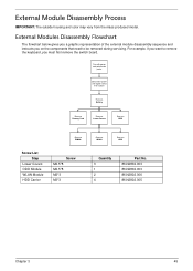
... the keyboard, you want to be removed during servicing. External Module Disassembly Process IMPORTANT: The outside housing and color may vary from system Rem ove Battery Rem ove Dummy Card Rem ove Lower Covers Rem ove ODD Rem ove DIMMs Screw List Step Lower Covers ODD Module WLAN Module HDD Carrier...
... the keyboard, you want to be removed during servicing. External Module Disassembly Process IMPORTANT: The outside housing and color may vary from system Rem ove Battery Rem ove Dummy Card Rem ove Lower Covers Rem ove ODD Rem ove DIMMs Screw List Step Lower Covers ODD Module WLAN Module HDD Carrier...

Service Guide
Page 56
Slide the battery lock in the direction shown. 2. Removing the Battery Pack 1. Slide and hold the battery release latch to the release position (1), then lift out the battery pack from the main unit (2). 2 1 46 Chapter 3 Turn computer over.
Slide the battery lock in the direction shown. 2. Removing the Battery Pack 1. Slide and hold the battery release latch to the release position (1), then lift out the battery pack from the main unit (2). 2 1 46 Chapter 3 Turn computer over.

Service Guide
Page 58
Remove the HDD cover as shown. Memory Cover HDD Cover Step Lower Covers Size M2.5*8 3. Carefully open the Memory Cover. 48 Chapter 3 Removing the Lower Covers 1. See "Removing the Battery Pack" on page 46. 2. Quantity 3 Screw Type 4. Remove the three screws securing the Memory and HDD Covers.
Remove the HDD cover as shown. Memory Cover HDD Cover Step Lower Covers Size M2.5*8 3. Carefully open the Memory Cover. 48 Chapter 3 Removing the Lower Covers 1. See "Removing the Battery Pack" on page 46. 2. Quantity 3 Screw Type 4. Remove the three screws securing the Memory and HDD Covers.

Service Guide
Page 59
See "Removing the Battery Pack" on page 46. 2. Pull the optical drive module out from the chassis. Step ODD Module Size M2.5*8 Quantity 1 Screw Type 3. Gently lever the ODD module out of the chassis. 4. Insert a suitable tool into the access slot in the battery bay as shown. Removing the Optical Drive Module 1. Chapter 3 49 Remove the screw securing the ODD module.
See "Removing the Battery Pack" on page 46. 2. Pull the optical drive module out from the chassis. Step ODD Module Size M2.5*8 Quantity 1 Screw Type 3. Gently lever the ODD module out of the chassis. 4. Insert a suitable tool into the access slot in the battery bay as shown. Removing the Optical Drive Module 1. Chapter 3 49 Remove the screw securing the ODD module.
Service Guide
Page 66
... ove Power Board Rem ove Left Speaker Module Rem ove Right Speaker Module Rem ove TouchPad Bracket Lower Cover Rem ove Mainboard Rem ove RTC Battery Rem ove Thermal Module Rem ove CPU Fan Rem ove CPU Screw List Step LCD Module LCD Module Upper Cover Upper Cover Power Board Left...
... ove Power Board Rem ove Left Speaker Module Rem ove Right Speaker Module Rem ove TouchPad Bracket Lower Cover Rem ove Mainboard Rem ove RTC Battery Rem ove Thermal Module Rem ove CPU Fan Rem ove CPU Screw List Step LCD Module LCD Module Upper Cover Upper Cover Power Board Left...
Service Guide
Page 67
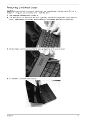
... Cover. 1. Work along the Switch Cover toward the left hinge, gently prying up the cover as shown. 4. The use of the computer. See "Removing the Battery Pack" on the right side of the Keyboard to expose the cutout. Lift the Switch Cover clear of plastic tools or fingers is recommended to...
... Cover. 1. Work along the Switch Cover toward the left hinge, gently prying up the cover as shown. 4. The use of the computer. See "Removing the Battery Pack" on the right side of the Keyboard to expose the cutout. Lift the Switch Cover clear of plastic tools or fingers is recommended to...

Service Guide
Page 85
Chapter 3 75 To replace the battery, solder the new battery to the Mainboard. The RTC Battery is soldered to the connections shown. Removing the RTC Battery IMPORTANT:Follow local regulations for disposal of all batteries.
Chapter 3 75 To replace the battery, solder the new battery to the Mainboard. The RTC Battery is soldered to the connections shown. Removing the RTC Battery IMPORTANT:Follow local regulations for disposal of all batteries.


