
Acer Aspire 7540 Notebook Series Start Guide
Page 5
...of wireless button/indicator LAN communication. Num Lock Lights up when Caps Lock is charging. 2. Protection fingerprint reader supporting Acer FingerNav 4-way control function (only for certain models). 9 Palmrest Comfortable support area for your computer. 6 Touchpad ...Power1 Indicates the computer's power status. Battery1 Indicates the computer's battery status. 1. Bluetooth communication button/indicator Enables/disables the Bluetooth function. Charging: The light shows amber when the battery is activated. 5 Keyboard For entering data into your hands when...
...of wireless button/indicator LAN communication. Num Lock Lights up when Caps Lock is charging. 2. Protection fingerprint reader supporting Acer FingerNav 4-way control function (only for certain models). 9 Palmrest Comfortable support area for your computer. 6 Touchpad ...Power1 Indicates the computer's power status. Battery1 Indicates the computer's battery status. 1. Bluetooth communication button/indicator Enables/disables the Bluetooth function. Charging: The light shows amber when the battery is activated. 5 Keyboard For entering data into your hands when...

Acer Aspire 7540 Notebook Series Start Guide
Page 10
Note: Do not cover or obstruct the opening of the fan. English 10 Base view 1 6 2 3 5 4 # Icon Item 1 Battery bay Description Houses the computer's battery pack. 2 Battery lock Locks the battery in position. 3 Battery release latch Releases the battery for removal. 4 Memory compartment Houses the computer's main memory. 5 Hard disk bay Houses the computer's hard disk (secured with screws). 6 Ventilation slots and Enable the computer to stay cool, cooling fan even after prolonged use.
Note: Do not cover or obstruct the opening of the fan. English 10 Base view 1 6 2 3 5 4 # Icon Item 1 Battery bay Description Houses the computer's battery pack. 2 Battery lock Locks the battery in position. 3 Battery release latch Releases the battery for removal. 4 Memory compartment Houses the computer's main memory. 5 Hard disk bay Houses the computer's hard disk (secured with screws). 6 Ventilation slots and Enable the computer to stay cool, cooling fan even after prolonged use.

Acer Aspire 7540 Notebook Series Start Guide
Page 12
... I/O interface Environment • 411 (W) x 274 (D) x 40/45.0 (H) mm (16.18 x 10.78 x 1.58/1.77 inches) • 3.2 kg (7.05 lbs.) with 6-cell battery pack* • 3.26 kg (7.19 lbs.) with 8-cell battery pack* • ACPI 3.0 • 71 W 4800 mAh* • 48.8 W 4400 mAh* • 3-pin 90 W AC adapter* • 3-pin 65 W AC adapter...
... I/O interface Environment • 411 (W) x 274 (D) x 40/45.0 (H) mm (16.18 x 10.78 x 1.58/1.77 inches) • 3.2 kg (7.05 lbs.) with 6-cell battery pack* • 3.26 kg (7.19 lbs.) with 8-cell battery pack* • ACPI 3.0 • 71 W 4800 mAh* • 48.8 W 4400 mAh* • 3-pin 90 W AC adapter* • 3-pin 65 W AC adapter...
Acer Aspire 7540 Service Guide
Page 7
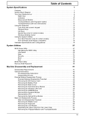
...Hot Keys 15 Special Key (only for certain models 15 Windows Mobility Center 16 Using the System Utilities 17 Acer Bio-Protection (only for certain models 17 Acer GridVista (dual-display compatible 18 Hardware Specifications and Configurations 19 System Utilities 27 BIOS Setup Utility 27 Navigating ... 42 Disassembly Process 42 External Module Disassembly Process 43 External Modules Disassembly Flowchart 43 Removing the SD Dummy Card 44 Removing the Battery Pack 45 Removing the Back Cover 46 Removing the Hard Disk Drive Module 48 Removing the Wireless LAN Card 50 Removing the ...
...Hot Keys 15 Special Key (only for certain models 15 Windows Mobility Center 16 Using the System Utilities 17 Acer Bio-Protection (only for certain models 17 Acer GridVista (dual-display compatible 18 Hardware Specifications and Configurations 19 System Utilities 27 BIOS Setup Utility 27 Navigating ... 42 Disassembly Process 42 External Module Disassembly Process 43 External Modules Disassembly Flowchart 43 Removing the SD Dummy Card 44 Removing the Battery Pack 45 Removing the Back Cover 46 Removing the Hard Disk Drive Module 48 Removing the Wireless LAN Card 50 Removing the ...
Acer Aspire 7540 Service Guide
Page 15
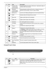
...Caps Lock Lights up when Num Lock is activated. 5 Keyboard For entering data into power-saving mode. Battery1 Indicates the computer's battery status. 1. Closed Front View 1 # Icon Item 1 Multi-in AC mode. 8 Click buttons The left and right buttons ...the status of wireless LAN communication. Indicates the status of Bluetooth communication. (only for certain models) Launches Acer Backup Management for sound recording. 12 Acer PowerSmart Puts your computer into your computer. 6 Touchpad Touch-sensitive pointing device which functions like a computer ...
...Caps Lock Lights up when Num Lock is activated. 5 Keyboard For entering data into power-saving mode. Battery1 Indicates the computer's battery status. 1. Closed Front View 1 # Icon Item 1 Multi-in AC mode. 8 Click buttons The left and right buttons ...the status of wireless LAN communication. Indicates the status of Bluetooth communication. (only for certain models) Launches Acer Backup Management for sound recording. 12 Acer PowerSmart Puts your computer into your computer. 6 Touchpad Touch-sensitive pointing device which functions like a computer ...
Acer Aspire 7540 Service Guide
Page 18
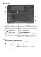
... Description Power Indicates the computer's power status. Bottom View 1 6 2 3 5 4 # Icon Item 1 Battery bay Description Houses the computer's battery pack. 2 Batter Lock 3 Battery release latch Locks the battery in AC mode. Fully charged: The light shows blue when in position. Houses the computer's hard disk (secured... to -read status indicators. Fully charged: The light shows green when in AC mode. 10 Chapter 1 Battery Indicates the computer's battery status. 1. Note: Do not cover or obstruct the opening of the fan. Charging: The light shows amber when the...
... Description Power Indicates the computer's power status. Bottom View 1 6 2 3 5 4 # Icon Item 1 Battery bay Description Houses the computer's battery pack. 2 Batter Lock 3 Battery release latch Locks the battery in AC mode. Fully charged: The light shows blue when in position. Houses the computer's hard disk (secured... to -read status indicators. Fully charged: The light shows green when in AC mode. 10 Chapter 1 Battery Indicates the computer's battery status. 1. Note: Do not cover or obstruct the opening of the fan. Charging: The light shows amber when the...
Acer Aspire 7540 Service Guide
Page 33
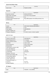
System Board Major Chips Item Audio Codec Keyboard Item Keyboard controller Total number of battery cell Package configuration Specification SONY/SANYO/PANASONIC/SIMPLO Li-ion 4400/4800mAh 6/8 3/4 cells in series, 2 series in parallel LCD 17.3" inch Item Vendor... Normally White 220 Specification 1.25 max. 400 typical 8 +3.3V 45/45 15/35 0 to +50 -40 to the USB port directly: Yes Battery Item Vendor Battery Type Pack capacity Number of keypads Windows logo key Internal & external keyboard work simultaneously Realtek ALC888s Controller Specification Winbond WPCE773 103-/104-/107-key...
System Board Major Chips Item Audio Codec Keyboard Item Keyboard controller Total number of battery cell Package configuration Specification SONY/SANYO/PANASONIC/SIMPLO Li-ion 4400/4800mAh 6/8 3/4 cells in series, 2 series in parallel LCD 17.3" inch Item Vendor... Normally White 220 Specification 1.25 max. 400 typical 8 +3.3V 45/45 15/35 0 to +50 -40 to the USB port directly: Yes Battery Item Vendor Battery Type Pack capacity Number of keypads Windows logo key Internal & external keyboard work simultaneously Realtek ALC888s Controller Specification Winbond WPCE773 103-/104-/107-key...
Acer Aspire 7540 Service Guide
Page 47
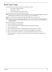
... power. 4. After POST, release Fn + ESC key. NOTE: If you do not have a crisis recovery disk at hand, then you use the Flash. If the battery pack does not contain enough power to finish BIOS flash, you use the Flash utility. Use the Flash utility to a bootable USB device containing the...
... power. 4. After POST, release Fn + ESC key. NOTE: If you do not have a crisis recovery disk at hand, then you use the Flash. If the battery pack does not contain enough power to finish BIOS flash, you use the Flash utility. Use the Flash utility to a bootable USB device containing the...

Acer Aspire 7540 Service Guide
Page 50
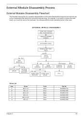
....00F87.735 86.9A554.4R0 86.9A536.3R5 86.9A552.3R0 42 Chapter 3 Disassembly Process The disassembly process is divided into the following : 1. Remove the battery pack. Turn off the power to any of the sequence to avoid damage to the system and all power and signal cables from the system...
....00F87.735 86.9A554.4R0 86.9A536.3R5 86.9A552.3R0 42 Chapter 3 Disassembly Process The disassembly process is divided into the following : 1. Remove the battery pack. Turn off the power to any of the sequence to avoid damage to the system and all power and signal cables from the system...
Acer Aspire 7540 Service Guide
Page 51
EXTERNAL MODULE DISASSEMBLY TURN OFF POWER AND PERIPHERALS UNPLUG POWER CABLES SD DUMMY CARD Cx1 ODD MODULE OPTICAL DISK DRIVE Hx1 OPTICAL LOCKER BRACKET REMOVE BATTERY PACK Cx4 BACK COVER Ax1 HDD MODULE DIMM MODULES Fx2 HARD DISK BRACKET HARD DISK DRIVE Screwx6 THERMAL MODULE Bx1 WLAN BOARD CPU Screw List ...
EXTERNAL MODULE DISASSEMBLY TURN OFF POWER AND PERIPHERALS UNPLUG POWER CABLES SD DUMMY CARD Cx1 ODD MODULE OPTICAL DISK DRIVE Hx1 OPTICAL LOCKER BRACKET REMOVE BATTERY PACK Cx4 BACK COVER Ax1 HDD MODULE DIMM MODULES Fx2 HARD DISK BRACKET HARD DISK DRIVE Screwx6 THERMAL MODULE Bx1 WLAN BOARD CPU Screw List ...

Acer Aspire 7540 Service Guide
Page 53
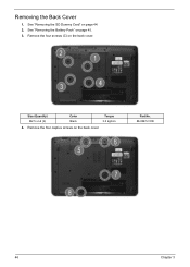
Note: Battery has been highlighted with the yellow circle as above image shows. Slide the battery release latch to the release position (a) to the unlock position. Chapter 3 45 Turn the notebook over so the bottom is facing up. 3. Slide the battery lock/unlock latch to pop out the battery pack, then remove the battery pack from the main unit (b). Please detach the battery and follow local regulations for disposal. 4. Removing the Battery Pack 1. See "Removing the SD Dummy Card" on page 44. 2.
Note: Battery has been highlighted with the yellow circle as above image shows. Slide the battery release latch to the release position (a) to the unlock position. Chapter 3 45 Turn the notebook over so the bottom is facing up. 3. Slide the battery lock/unlock latch to pop out the battery pack, then remove the battery pack from the main unit (b). Please detach the battery and follow local regulations for disposal. 4. Removing the Battery Pack 1. See "Removing the SD Dummy Card" on page 44. 2.
Acer Aspire 7540 Service Guide
Page 54
Remove the four captive screws on page 44. 2. Size (Quantity) M2.5 x L6 (4) Color Black Torque 3.0 kgf-cm 4. See "Removing the SD Dummy Card" on the back cover. Part No. 86.00E12.536 46 Chapter 3 Remove the four screws (C) on page 45. 3. See "Removing the Battery Pack" on the back cover. Removing the Back Cover 1.
Remove the four captive screws on page 44. 2. Size (Quantity) M2.5 x L6 (4) Color Black Torque 3.0 kgf-cm 4. See "Removing the SD Dummy Card" on the back cover. Part No. 86.00E12.536 46 Chapter 3 Remove the four screws (C) on page 45. 3. See "Removing the Battery Pack" on the back cover. Removing the Back Cover 1.
Acer Aspire 7540 Service Guide
Page 56
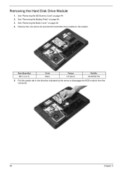
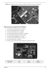
Size (Quantity) M2.5 x L4 (1) Color Black Torque 3.0 kgf-cm Part No. 86.00H59.734 5. Remove the one screw (A) securing the hard disk drive module to disengage the HDD module from the connector. 48 Chapter 3 See "Removing the SD Dummy Card" on page 46. 4. See "Removing the Back Cover" on page 44. 2. Pull the plastic tab in the direction indicated by the arrow to the system. See "Removing the Battery Pack" on page 45. 3. Removing the Hard Disk Drive Module 1.
Size (Quantity) M2.5 x L4 (1) Color Black Torque 3.0 kgf-cm Part No. 86.00H59.734 5. Remove the one screw (A) securing the hard disk drive module to disengage the HDD module from the connector. 48 Chapter 3 See "Removing the SD Dummy Card" on page 46. 4. See "Removing the Back Cover" on page 44. 2. Pull the plastic tab in the direction indicated by the arrow to the system. See "Removing the Battery Pack" on page 45. 3. Removing the Hard Disk Drive Module 1.
Acer Aspire 7540 Service Guide
Page 58
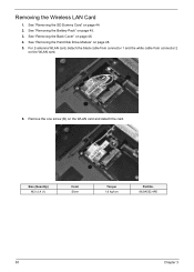
Size (Quantity) M2 x L4 (1) Color Silver Torque 1.6 kgf-cm Part No. 86.9A552.4R0 50 Chapter 3 For 2-antenna WLAN card, detach the black cable from connector 1 and the white cable from connector 2 on the WLAN card and detach the card. Remove the one screw (B) on the WLAN card. 6. See "Removing the Back Cover" on page 48. 5. See "Removing the Hard Disk Drive Module" on page 46. 4. See "Removing the SD Dummy Card" on page 45. 3. Removing the Wireless LAN Card 1. See "Removing the Battery Pack" on page 44. 2.
Size (Quantity) M2 x L4 (1) Color Silver Torque 1.6 kgf-cm Part No. 86.9A552.4R0 50 Chapter 3 For 2-antenna WLAN card, detach the black cable from connector 1 and the white cable from connector 2 on the WLAN card and detach the card. Remove the one screw (B) on the WLAN card. 6. See "Removing the Back Cover" on page 48. 5. See "Removing the Hard Disk Drive Module" on page 46. 4. See "Removing the SD Dummy Card" on page 45. 3. Removing the Wireless LAN Card 1. See "Removing the Battery Pack" on page 44. 2.
Acer Aspire 7540 Service Guide
Page 59
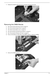
See "Removing the Battery Pack" on page 46. 4. Remove the DIMM module(s). See "Removing the Back Cover" on page 45. 3. See "Removing the Wireless LAN Card" on page 48. 5. Chapter 3 51 Release the wireless LAN card from its connector and detach the card. See "Removing the Hard Disk Drive Module" on page 50. 6. Removing the DIMM Module 1. Push out the latches on page 44. 2. See "Removing the SD Dummy Card" on both sides of the DIMM sockets to release the DIMMs. 7. 7.
See "Removing the Battery Pack" on page 46. 4. Remove the DIMM module(s). See "Removing the Back Cover" on page 45. 3. See "Removing the Wireless LAN Card" on page 48. 5. Chapter 3 51 Release the wireless LAN card from its connector and detach the card. See "Removing the Hard Disk Drive Module" on page 50. 6. Removing the DIMM Module 1. Push out the latches on page 44. 2. See "Removing the SD Dummy Card" on both sides of the DIMM sockets to release the DIMMs. 7. 7.
Acer Aspire 7540 Service Guide
Page 60
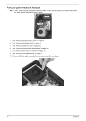
See "Removing the SD Dummy Card" on page 45. 3. See "Removing the Battery Pack" on page 44. 2. See "Removing the Hard Disk Drive Module" on page 51. 7. For this section, we are two version of heatsink module. See "...
See "Removing the SD Dummy Card" on page 45. 3. See "Removing the Battery Pack" on page 44. 2. See "Removing the Hard Disk Drive Module" on page 51. 7. For this section, we are two version of heatsink module. See "...
Acer Aspire 7540 Service Guide
Page 62
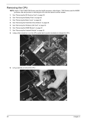
See "Removing the Battery Pack" on page 48. 5. See "Removing the Hard Disk Drive Module" on page 45. 3. See "Removing the DIMM Module" on page 44. 2. Using a flat screwdriver, ... 3 Lift up carefully to release the CPU. 9. See "Removing the SD Dummy Card" on page 51. 7. Removing the CPU NOTE: Aspire 7736/7736Z/7336 Series uses the Intel® processor, while Aspire 7540 Series uses the AMD® processor. See "Removing the Back Cover" on page 52. 8. See "Removing the Heatsink Module" on...
See "Removing the Battery Pack" on page 48. 5. See "Removing the Hard Disk Drive Module" on page 45. 3. See "Removing the DIMM Module" on page 44. 2. Using a flat screwdriver, ... 3 Lift up carefully to release the CPU. 9. See "Removing the SD Dummy Card" on page 51. 7. Removing the CPU NOTE: Aspire 7736/7736Z/7336 Series uses the Intel® processor, while Aspire 7540 Series uses the AMD® processor. See "Removing the Back Cover" on page 52. 8. See "Removing the Heatsink Module" on...
Acer Aspire 7540 Service Guide
Page 63
... Pin 1 at the corner as shown. Size (Quantity) M2.5 x L6 (1) Chapter 3 Color Black Torque 3.0 kgf-cm Part No. 86.00E12.536 55 See "Removing the Battery Pack" on page 46. 4. See "Removing the Back Cover" on page 45. 3. See "Removing the Hard Disk Drive Module" on page 51. 7. See "Removing the...
... Pin 1 at the corner as shown. Size (Quantity) M2.5 x L6 (1) Chapter 3 Color Black Torque 3.0 kgf-cm Part No. 86.00E12.536 55 See "Removing the Battery Pack" on page 46. 4. See "Removing the Back Cover" on page 45. 3. See "Removing the Hard Disk Drive Module" on page 51. 7. See "Removing the...
Acer Aspire 7540 Service Guide
Page 66
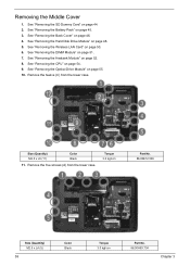
..." on page 44. 2. Remove the twelve (C) from the lower case. Removing the Middle Cover 1. See "Removing the DIMM Module" on page 45. 3. See "Removing the Battery Pack" on page 51. 7. See "Removing the Wireless LAN Card" on page 48. 5. See "Removing the Hard Disk Drive Module" on page 50. 6. See "Removing...
..." on page 44. 2. Remove the twelve (C) from the lower case. Removing the Middle Cover 1. See "Removing the DIMM Module" on page 45. 3. See "Removing the Battery Pack" on page 51. 7. See "Removing the Wireless LAN Card" on page 48. 5. See "Removing the Hard Disk Drive Module" on page 50. 6. See "Removing...

Acer Aspire 7540 Service Guide
Page 68
Turn it over on page 45. 3. Removing the Keyboard 1. See "Removing the Battery Pack" on the touchpad area. 60 Chapter 3 See "Removing the Optical Drive Module" on page 51. 7. See "Removing the DIMM Module" on page 55. 10. ...
Turn it over on page 45. 3. Removing the Keyboard 1. See "Removing the Battery Pack" on the touchpad area. 60 Chapter 3 See "Removing the Optical Drive Module" on page 51. 7. See "Removing the DIMM Module" on page 55. 10. ...


